EP4443141A1 - Système et procédé de contrôle de défauts de surface sur un objet à contrôler - Google Patents
Système et procédé de contrôle de défauts de surface sur un objet à contrôler Download PDFInfo
- Publication number
- EP4443141A1 EP4443141A1 EP23166884.9A EP23166884A EP4443141A1 EP 4443141 A1 EP4443141 A1 EP 4443141A1 EP 23166884 A EP23166884 A EP 23166884A EP 4443141 A1 EP4443141 A1 EP 4443141A1
- Authority
- EP
- European Patent Office
- Prior art keywords
- test
- test body
- illumination
- source
- wavelength range
- Prior art date
- Legal status (The legal status is an assumption and is not a legal conclusion. Google has not performed a legal analysis and makes no representation as to the accuracy of the status listed.)
- Pending
Links
Images
Classifications
-
- G—PHYSICS
- G01—MEASURING; TESTING
- G01N—INVESTIGATING OR ANALYSING MATERIALS BY DETERMINING THEIR CHEMICAL OR PHYSICAL PROPERTIES
- G01N21/00—Investigating or analysing materials by the use of optical means, i.e. using sub-millimetre waves, infrared, visible or ultraviolet light
- G01N21/84—Systems specially adapted for particular applications
- G01N21/88—Investigating the presence of flaws or contamination
- G01N21/8806—Specially adapted optical and illumination features
-
- G—PHYSICS
- G01—MEASURING; TESTING
- G01N—INVESTIGATING OR ANALYSING MATERIALS BY DETERMINING THEIR CHEMICAL OR PHYSICAL PROPERTIES
- G01N21/00—Investigating or analysing materials by the use of optical means, i.e. using sub-millimetre waves, infrared, visible or ultraviolet light
- G01N21/84—Systems specially adapted for particular applications
- G01N21/88—Investigating the presence of flaws or contamination
- G01N21/8851—Scan or image signal processing specially adapted therefor, e.g. for scan signal adjustment, for detecting different kinds of defects, for compensating for structures, markings, edges
-
- G—PHYSICS
- G01—MEASURING; TESTING
- G01N—INVESTIGATING OR ANALYSING MATERIALS BY DETERMINING THEIR CHEMICAL OR PHYSICAL PROPERTIES
- G01N21/00—Investigating or analysing materials by the use of optical means, i.e. using sub-millimetre waves, infrared, visible or ultraviolet light
- G01N21/84—Systems specially adapted for particular applications
- G01N21/88—Investigating the presence of flaws or contamination
- G01N21/95—Investigating the presence of flaws or contamination characterised by the material or shape of the object to be examined
- G01N21/9515—Objects of complex shape, e.g. examined with use of a surface follower device
Definitions
- the present invention relates to a system for testing a surface of a test object, the system comprising: a first source and a second source, the first source and the second source being designed such that the first source generates and emits a first electromagnetic radiation in a first wavelength range during operation of the system and the second source generates and emits a second electromagnetic radiation in a second wavelength range during operation of the system, the first source being arranged such that the first source illuminates the test object from a first illumination direction during operation of the system, the second source being arranged such that the second source illuminates the test object from a second illumination direction during operation of the system, the first and second illumination directions being different from one another, a first camera for capturing a first image of the test object from a first observation direction and an evaluation device, the evaluation device being operatively connected to the first camera such that the evaluation device receives a first image data set describing the first image captured by the first camera during operation of the system.
- the invention also relates to a method for testing a surface of a test body, the method comprising the steps of: illuminating the test body with a first electromagnetic radiation in a first wavelength range from a first illumination direction, illuminating the test body with a second electromagnetic radiation in a second wavelength range from a second illumination direction, the first and second illumination directions being different from one another, and capturing a first image of the test body from a first observation direction.
- test specimens that have complex shapes and are manufactured in large quantities or even exist as bulk material are difficult to test automatically. Imperfections on the respective surface of a test specimen such as dents, impact marks, underfills or other defects cannot usually be distinguished from contamination, color changes or a deviation in the surface roughness during an automated test.
- a very reliable inspection is still achieved with a visual inspection by a visual inspector.
- the visual inspector turns the respective test specimen under lateral light incidence and observes the changing brightness due to the light reflection or scattering.
- the continued outstanding quality of a visual inspection is due in particular to the fact that a visual inspector has experience that enables him to distinguish between real defects and, for example, pure discoloration of the surface of the test specimen.
- the evaluation device of the system of the type mentioned at the outset is set up such that the evaluation device, during operation of the system, simulates a first reference image data set from a data model of the test object, which takes into account illumination of the test object from the first illumination direction and illumination of the test object from the second illumination direction and image capture from the first observation direction and generates a first error signal from a comparison between the first image data set and the first reference image data set.
- the idea underlying the invention is to base the first image captured by the camera on a defined lighting situation with the first electromagnetic radiation and the second electromagnetic radiation from two distinct, mutually different first and second lighting directions. Such a defined lighting situation can be simulated with reasonable computational effort.
- the simulated The first reference image data set then serves as the basis for a target value adjustment and for the generation of an error signal.
- the simulated physical system consisting of the first, second source and optionally any other source as well as the electromagnetic radiation generated by these sources and the first camera and optionally any other camera is sufficiently defined so that this physical system can be used as the basis for the simulation.
- the first and second illumination directions and the first observation direction must be used as the basis for the simulation.
- the first reference image data set is simulated by raycasting or raytracing.
- a data model of the test body for example a CAD model, is used to simulate what an expected first image from the first camera would ideally look like. This expected first image then forms the first reference image data set.
- the evaluation device compares the first reference image data set with the first image data set.
- An error signal is then calculated, which indicates a measure of a deviation between the first image data set and the first reference image data set. In one embodiment, the error signal also describes the location of a deviation on the test body between the first reference image data set and the first image data set.
- the system comprises more than two sources of electromagnetic radiation.
- the system therefore has a third source, wherein the third source is designed such that the third source generates and emits a third electromagnetic radiation in a third wavelength range during operation of the system, wherein the third source is arranged such that the third source illuminates the test body from a third illumination direction during operation of the system, and wherein the third illumination direction is different from the first and second illumination directions.
- the system has more than three sources.
- the system is designed such that the first electromagnetic radiation and the second electromagnetic radiation and optionally also the third electromagnetic radiation can be distinguished from one another when captured by the first camera.
- the electromagnetic radiation from all sources can be distinguished from one another.
- the test body is illuminated with the first electromagnetic radiation and the second electromagnetic radiation and optionally with the third electromagnetic radiation at different times, so that the test body is illuminated either with the first electromagnetic radiation or with the second electromagnetic radiation or with the third electromagnetic radiation.
- Each image data set but in particular the first image data set, then describes two or three images, namely an image that was generated with the first electromagnetic radiation, a first image that was illuminated with the second electromagnetic radiation and possibly a third image that was illuminated with the second electromagnetic radiation. If, for example, the two or three images are then displayed in the first image data set with different colors, impact points can be recognized, for example, because an impact point has a different color than its surroundings.
- the first wavelength range, the second wavelength range and optionally the third wavelength range are different from one another.
- the first electromagnetic radiation, the second electromagnetic radiation and possibly the third electromagnetic radiation can also be distinguished from one another when captured with the first camera.
- Such a selection of the first and second wavelength ranges and optionally the third wavelength range makes it possible to carry out the image analysis in the same way as was previously described for the temporal distinguishability between the first electromagnetic radiation and the second electromagnetic radiation and optionally the third electromagnetic radiation. However, it is possible to capture all images of the first image data set simultaneously.
- the first wavelength range, the second wavelength range and optionally the third wavelength range are taken into account when simulating the reference image data set.
- the wavelength ranges of all electromagnetic radiation generated by the sources are different from each other.
- each of the three sources nevertheless has only one of the three wavelength ranges, so that all wavelength ranges can be captured separately by a color camera. Therefore, in an embodiment of the invention, the system has a number N of first sources that generate and emit first electromagnetic radiation in the first wavelength range, a number N of sources that generate and emit second electromagnetic radiation in the second wavelength range, and a number N of third sources that generate and emit third electromagnetic radiation in the third wavelength range. This total number of sources is an integer multiple N of three in such an embodiment.
- the first wavelength range has a first centroid wavelength and the second wavelength range has a second centroid wavelength and the optional third wavelength range has a third centroid wavelength.
- the first and second and optionally the third centroid wavelengths are different from one another.
- the sources of the system according to the invention are designed such that they generate and emit electromagnetic radiation with a directed component when the system is operating. In one embodiment, the sources of the system according to the invention are designed such that they generate and emit directed electromagnetic radiation when the system is operating. In this way, a defined direction of illumination is provided, which can also be simulated in the evaluation device. In this application, directed electromagnetic radiation is understood as the opposite of diffuse electromagnetic radiation.
- two illumination directions of electromagnetic radiation with mutually different wavelength ranges each enclose an angle in a range of 30° to 150°.
- the first camera is a color camera with a plurality of pixels.
- Each of the plurality of pixels has at least two sensors that are sensitive to a respective sensor wavelength range, the sensor wavelength ranges of the two sensors being different from one another.
- each from the plurality of pixels exactly three sensors each sensitive to a sensor wavelength range, wherein the sensor wavelength ranges of the three sensors are different from one another.
- Such an embodiment can be easily implemented with a commercially available color camera, for example a CCD or CMOS camera.
- the three sensors typically have three filters for red, green and blue light in order to generate an image data set that represents the most complete description of the image in the R-G-B color space possible.
- the system has a plurality of cameras which capture an image of the test object from a plurality of different observation directions.
- the system therefore has a second camera for capturing a second image of the test specimen from a second observation direction.
- the second observation direction is different from the first observation direction and the evaluation device is also effectively connected to the second camera such that the evaluation device, when the system is operating, contains a second image data set captured by the second camera and describing the second image.
- the evaluation device is set up such that, when the system is operating, it simulates a second reference image data set from the data model of the test specimen, which takes into account the illumination of the test specimen from the first illumination direction, the illumination of the test specimen from the second illumination direction and an image capture from the second observation direction.
- the evaluation device then generates a second error signal from a comparison between the second image data set and the second reference image data set.
- the first and second electromagnetic radiation have different wavelength ranges from one another.
- the first camera and the second camera are each color cameras, so that both cameras capture a color image and thus the first electromagnetic radiation and the second electromagnetic radiation simultaneously but with separate sensors.
- the first camera only captures the first electromagnetic radiation and the second camera only captures the second electromagnetic radiation.
- a color filter is arranged in front of the first and second cameras.
- the system has a device for detecting at least one position or orientation of the test body relative to the first camera.
- the evaluation device is effectively connected to the device for detecting at least the position or orientation of the test body such that the evaluation device receives information about at least the position or orientation of the test body at a first detection time of the first image during operation of the system, wherein the evaluation device is set up such that the evaluation device simulates the first reference image data set during operation of the system, wherein the information about at least the position or orientation of the test body at the first detection time is taken into account.
- At least the position or the orientation of the test object is recorded at the first recording time of the first image, i.e. at the same time as the recording of the first image.
- at least the position or the orientation of the test object is recorded before the first recording time of the first image and then at least the position or the orientation of the test object at the first recording time is deduced from at least the recorded position or the recorded orientation. This is possible in particular if the test object undergoes a translation (change in position relative to the first camera) but no rotation (change in orientation relative to the first camera) after at least the position or the orientation has been recorded.
- the pose of the test object relative to the first camera i.e. its position and its orientation in space relative to the first camera, must be fully detected.
- At least the position or the orientation is captured for each capture time.
- at least the position or the orientation of the test body at the capture times is inferred from at least the captured position or the captured orientation of the test body. This is particularly the case possible if the test object experiences a translation (change in position relative to the first camera) but no rotation (change in orientation relative to the first camera) between two acquisition times.
- the device for detecting at least the positions or the orientation of the test body is an additional camera whose image data sets are not used for comparison with the reference image data set. In one embodiment, however, the device for detecting at least the position or the orientation of the test body comprises the first and/or the second and/or the third camera. In one embodiment of the invention, a grayscale image of the first and/or the second and/or the third camera is used to detect at least the position or the orientation of the test body relative to the first camera.
- the system has a test track with at least one test point arranged on the test track and a test specimen feed unit, wherein the test specimen feed unit is set up such that, during operation, it feeds the test specimen to the test track so that the test specimen moves on the test track.
- the first source and the second source and optionally any further source are set up and arranged such that, during operation of the system, they illuminate the test specimen at least at the test point with the first electromagnetic radiation and the second electromagnetic radiation and any further electromagnetic radiation.
- the first camera, the second camera and optionally any second camera are set up and arranged such that, during operation of the system, they capture the test specimen at least at the test point from the first observation direction and the second observation direction.
- An example of such a test track is a conveyor belt onto which the test object or a plurality of test objects is placed using the test specimen feed unit and which guides the test object to and from the test point.
- the system comprises a conveyor belt, wherein the test body can be arranged on the conveyor belt and wherein the conveyor belt is designed and arranged such that it leads to the operation of the system in the test body along the test section.
- the object feed unit has a conveyor, wherein the conveyor has a discharge end so that the test object flies along the test track during operation of the system.
- a test track, along which the test object flies describes a straight line, a parabola or a partial circle shape in sections.
- the method of the type mentioned at the outset further comprises the steps of: simulating a first reference image data set from a data model of the test body, wherein the simulation takes into account illumination of the test body from the first illumination direction and illumination of the test body from the second illumination direction and image capture from the first observation direction, and generating an error signal from a comparison of a first image data set describing the first image with the first reference image data set.
- the test specimen is illuminated with the first electromagnetic radiation and the second electromagnetic radiation simultaneously, wherein the first wavelength range and the second wavelength range are different from one another.
- the acquisition of the first image of the test body at a first acquisition time comprises the step of: capturing at least one position or one orientation of the test body at the first release time, wherein the simulation of the first reference image data set takes into account at least the position or the orientation of the test body at the first release time.
- the test body comprises a metal or a plastic, wherein the method according to the invention serves to detect a discontinuity on the surface.
- a discontinuity is an impact point, an underfill or another deformation of the surface that is not desired.
- the method according to the invention is suitable for testing a surface of a metal or plastic casting as well as a metal forging.
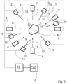
- Figure 1 is a schematic plan view from above of a system 1 according to the invention for testing a surface 2 of a test specimen 3.
- the system 1 shown and described below as an example is a free fall arrangement in which the individual test specimens 3 fall in free fall along a test section 10.
- the test section 10 runs perpendicular to the plane of the illustration Figure 1 .
- Such a free-fall arrangement allows the surface 2 of the individual test specimens 3 to be tested completely, ie on all sides.
- the display level from Figure 1 shows the test specimen 3 at a test point 11 on the test track 10. All sources 4, 5, 6 for the illumination and all cameras 12 for taking images of the surface 2 of the test specimen 3 are arranged such that they illuminate or capture the test specimen 3 at this test point 11.
- the system 1 has a total of six sources 4, 5, 6 for electromagnetic radiation, which illuminates the test object 3.
- the sources designated with the reference number 4 generate electromagnetic radiation 7 in the red wavelength range and emit it. These red sources 4 are also referred to as first sources and emit first electromagnetic radiation 7.
- the sources designated with the reference number 5 generate electromagnetic radiation 8 in the green wavelength range and emit it. These green sources 5 are also referred to as second sources and emit second electromagnetic radiation 8.
- the sources designated with the reference number 6 generate electromagnetic radiation 9 in the blue wavelength range and emit it. These blue sources 6 are also referred to as third sources and emit third electromagnetic radiation 9.
- sources of the same color are offset by 180°, ie arranged opposite each other. Due to the color coding of the individual sources 4, 5, 6, they can illuminate the test object 3 simultaneously and yet Observation direction 13 of the cameras 12 makes it possible to determine which surface section primarily reflects or scatters which electromagnetic radiation 7, 8, 9 in the observation direction 13 of the respective camera 12. In order to ensure this "distinguishability" of the respective source 4, 5, 6 from which the radiation 7, 8, 9 detected by the camera 12 originates, the sources 4, 5, 6 are designed in such a way that the emitted electromagnetic radiation 7, 8, 9 is largely directed.
- the system 1 from Figure 1 comprises six cameras, all of which have different observation directions 13. In this way, images of the test object are obtained which together show the test object 3 from all sides and thus the surface 2 of the test object 3 in its entirety.
- Each of the cameras 12 is a commercially available color camera. In each of these color cameras, each pixel is formed by three sensors for the primary colors red, green and blue (RGB color space).
- Each of the cameras 12 is connected to a computer 15 as an evaluation device via a signal line 14.
- a data processing program runs on the computer 15, which compares each of the images recorded by the six cameras 12 or the image data set describing the respective image with a reference image data set.
- the test body 3 can assume any orientation relative to the cameras 12 on its flight path.
- the position of the respective test body 3 relative to the cameras 12 at the time of capture can vary from test body 3 to test body 3. Therefore, the computer 15 first evaluates the grayscale images generated by the individual cameras 12 and determines the pose, i.e. position and orientation, of the respective test body 3 at the time of capture.
- the data processing program simulates for the previously calculated pose of the test object from a CAD model 16 of the test object by ray tracing what an expected first image of the test object 3, which the first camera 12 would capture, would ideally look like.
- This simulated, expected image is described as the first reference image data set.
- the first reference image data set simulated in this way then serves as the basis for a target value comparison and for generating an error signal.
- the error signal marks the location of a deviation between the first reference image data set and the first image data set.
- This type of evaluation is carried out by the computer 15 with the data processing program for each of the six cameras 12. Due to the defined lighting situation with the first electromagnetic radiation 7, the second electromagnetic radiation 8 and the third electromagnetic radiation 9 from different illumination directions and with different wavelength ranges, the simulations for generating the reference image data sets are comparatively less computationally intensive. In addition, deviations from the target shape of the surface are clearly visible due to the different wavelength ranges.
Landscapes
- Physics & Mathematics (AREA)
- Health & Medical Sciences (AREA)
- Life Sciences & Earth Sciences (AREA)
- Chemical & Material Sciences (AREA)
- Analytical Chemistry (AREA)
- Biochemistry (AREA)
- General Health & Medical Sciences (AREA)
- General Physics & Mathematics (AREA)
- Immunology (AREA)
- Pathology (AREA)
- Engineering & Computer Science (AREA)
- Computer Vision & Pattern Recognition (AREA)
- Signal Processing (AREA)
- Investigating Materials By The Use Of Optical Means Adapted For Particular Applications (AREA)
Priority Applications (1)
| Application Number | Priority Date | Filing Date | Title |
|---|---|---|---|
| EP23166884.9A EP4443141A1 (fr) | 2023-04-05 | 2023-04-05 | Système et procédé de contrôle de défauts de surface sur un objet à contrôler |
Applications Claiming Priority (1)
| Application Number | Priority Date | Filing Date | Title |
|---|---|---|---|
| EP23166884.9A EP4443141A1 (fr) | 2023-04-05 | 2023-04-05 | Système et procédé de contrôle de défauts de surface sur un objet à contrôler |
Publications (1)
| Publication Number | Publication Date |
|---|---|
| EP4443141A1 true EP4443141A1 (fr) | 2024-10-09 |
Family
ID=85980555
Family Applications (1)
| Application Number | Title | Priority Date | Filing Date |
|---|---|---|---|
| EP23166884.9A Pending EP4443141A1 (fr) | 2023-04-05 | 2023-04-05 | Système et procédé de contrôle de défauts de surface sur un objet à contrôler |
Country Status (1)
| Country | Link |
|---|---|
| EP (1) | EP4443141A1 (fr) |
Citations (4)
| Publication number | Priority date | Publication date | Assignee | Title |
|---|---|---|---|---|
| US20050201611A1 (en) * | 2004-03-09 | 2005-09-15 | Lloyd Thomas Watkins Jr. | Non-contact measurement method and apparatus |
| US20150355102A1 (en) * | 2014-06-09 | 2015-12-10 | Keyence Corporation | Image Inspection Apparatus, Image Inspection Method, Image Inspection Program, Computer-Readable Recording Medium And Recording Device |
| JP2018151242A (ja) * | 2017-03-13 | 2018-09-27 | 株式会社Screenホールディングス | 検査装置および検査方法 |
| US20210272257A1 (en) * | 2020-02-28 | 2021-09-02 | SCREEN Holdings Co., Ltd. | Inspection method and inspection apparatus |
-
2023
- 2023-04-05 EP EP23166884.9A patent/EP4443141A1/fr active Pending
Patent Citations (4)
| Publication number | Priority date | Publication date | Assignee | Title |
|---|---|---|---|---|
| US20050201611A1 (en) * | 2004-03-09 | 2005-09-15 | Lloyd Thomas Watkins Jr. | Non-contact measurement method and apparatus |
| US20150355102A1 (en) * | 2014-06-09 | 2015-12-10 | Keyence Corporation | Image Inspection Apparatus, Image Inspection Method, Image Inspection Program, Computer-Readable Recording Medium And Recording Device |
| JP2018151242A (ja) * | 2017-03-13 | 2018-09-27 | 株式会社Screenホールディングス | 検査装置および検査方法 |
| US20210272257A1 (en) * | 2020-02-28 | 2021-09-02 | SCREEN Holdings Co., Ltd. | Inspection method and inspection apparatus |
Similar Documents
| Publication | Publication Date | Title |
|---|---|---|
| DE69523853T2 (de) | Verfahren und Vorrichtung zur Kontrollierung von hauptsachlich runden Gegenständen | |
| EP1716410B1 (fr) | Procede et dispositif pour contrôler des surfaces | |
| EP1132732A2 (fr) | Procédé pour évaluer des criques structurales sur la surface d'une plaquette semiconductrice | |
| DE102015116047A1 (de) | Prüfvorrichtung und Steuerverfahren für eine Prüfvorrichtung | |
| DE69110463T2 (de) | Kontrolle von kleidungsstücken. | |
| EP3912127A1 (fr) | Procédé et dispositif d'inspection de composants difficiles à atteindre | |
| EP3004851B1 (fr) | Procédé de détermination de la puissance de réfraction d'un objet transparent et dispositif correspondant | |
| DE102017219244B4 (de) | Inspektionsbedingungsbestimmungseinrichtung, inspektionsbedingungsbestimmungsverfahren und inspektionsbedingungsbestimmungsprogramm | |
| DE102020109945A1 (de) | Verfahren und Inspektionseinrichtung zur optischen Inspektion einer Oberfläche | |
| DE102010032241A1 (de) | Verfahren und Vorrichtung zum Erkennen von Oberflächenfehlern | |
| DE102013108722B4 (de) | Verfahren und Vorrichtung zum Erfassen von Defekten einer ebenen Oberfläche | |
| DE69205811T2 (de) | Verfahren zur Bildanalyse. | |
| EP1600764A1 (fr) | Procédé et dispositif d'inspection d'objets transparents | |
| DE102017102338A1 (de) | Verfahren und Vorrichtung zum Auffinden oder Untersuchen von Oberflächendefekten in einer mehrschichtigen Oberfläche | |
| DE4434475C2 (de) | Verfahren und Vorrichtung zur Qualitätskontrolle eines Gegenstandes, insbesondere einer Compact-Disc | |
| EP4443141A1 (fr) | Système et procédé de contrôle de défauts de surface sur un objet à contrôler | |
| DE102014209000A1 (de) | Optische Prüfung von stabförmigen Artikeln der Tabak verarbeitenden Industrie | |
| DE102016012371A1 (de) | Verfahren und Anlage zum Ermitteln der Defektfläche mindestens einer Fehlstelle auf mindestens einer Funktionsoberfläche eines Bauteils oder Prüfkörpers | |
| DE102016224000B4 (de) | Verfahren und Vorrichtung zur Detektion eines Werkzeugbruches | |
| DE102016010833A1 (de) | Prüfraum zur Inspektion einer Oberflächenbeschaffenhait einer Prüfoberfläche | |
| DE19527446A1 (de) | Verfahren und Vorrichtung zur optischen Oberflächenprüfung von Werkstücken | |
| DE102022107133A1 (de) | Komponenteninspektionssystem und -verfahren bei produktionsgeschwindigkeit | |
| DE102022110231A1 (de) | Verfahren, Softwareprogramm und System zum Erfassen von Bildunregelmäßigkeiten in von einem videoendoskopischen Instrument erzeugten Bildern | |
| DE112010004292B4 (de) | System und Verfahren zur Ausrichtung und Inspektion von Ball Grid Array Geräten | |
| DE102017009153A1 (de) | Anordnung und Verfahren zur Inspektion von bewegten plattenförmigen Objekten |
Legal Events
| Date | Code | Title | Description |
|---|---|---|---|
| PUAI | Public reference made under article 153(3) epc to a published international application that has entered the european phase |
Free format text: ORIGINAL CODE: 0009012 |
|
| STAA | Information on the status of an ep patent application or granted ep patent |
Free format text: STATUS: THE APPLICATION HAS BEEN PUBLISHED |
|
| AK | Designated contracting states |
Kind code of ref document: A1 Designated state(s): AL AT BE BG CH CY CZ DE DK EE ES FI FR GB GR HR HU IE IS IT LI LT LU LV MC ME MK MT NL NO PL PT RO RS SE SI SK SM TR |
|
| STAA | Information on the status of an ep patent application or granted ep patent |
Free format text: STATUS: REQUEST FOR EXAMINATION WAS MADE |
|
| 17P | Request for examination filed |
Effective date: 20250408 |