EP4443252A1 - Aufbauverfahren zur gleichzeitigen konfiguration einer vielzahl von elektronisch gesteuerten garnliefervorrichtungen in einem textilverfahren - Google Patents
Aufbauverfahren zur gleichzeitigen konfiguration einer vielzahl von elektronisch gesteuerten garnliefervorrichtungen in einem textilverfahren Download PDFInfo
- Publication number
- EP4443252A1 EP4443252A1 EP24167372.2A EP24167372A EP4443252A1 EP 4443252 A1 EP4443252 A1 EP 4443252A1 EP 24167372 A EP24167372 A EP 24167372A EP 4443252 A1 EP4443252 A1 EP 4443252A1
- Authority
- EP
- European Patent Office
- Prior art keywords
- yarn
- yarn feeders
- gateway
- textile machine
- setup
- Prior art date
- Legal status (The legal status is an assumption and is not a legal conclusion. Google has not performed a legal analysis and makes no representation as to the accuracy of the status listed.)
- Pending
Links
Images

Classifications
-
- G—PHYSICS
- G05—CONTROLLING; REGULATING
- G05B—CONTROL OR REGULATING SYSTEMS IN GENERAL; FUNCTIONAL ELEMENTS OF SUCH SYSTEMS; MONITORING OR TESTING ARRANGEMENTS FOR SUCH SYSTEMS OR ELEMENTS
- G05B19/00—Program-control systems
- G05B19/02—Program-control systems electric
- G05B19/418—Total factory control, i.e. centrally controlling a plurality of machines, e.g. direct or distributed numerical control [DNC], flexible manufacturing systems [FMS], integrated manufacturing systems [IMS] or computer integrated manufacturing [CIM]
- G05B19/4184—Total factory control, i.e. centrally controlling a plurality of machines, e.g. direct or distributed numerical control [DNC], flexible manufacturing systems [FMS], integrated manufacturing systems [IMS] or computer integrated manufacturing [CIM] characterised by fault tolerance, reliability of production system
-
- B—PERFORMING OPERATIONS; TRANSPORTING
- B65—CONVEYING; PACKING; STORING; HANDLING THIN OR FILAMENTARY MATERIAL
- B65H—HANDLING THIN OR FILAMENTARY MATERIAL, e.g. SHEETS, WEBS, CABLES
- B65H63/00—Warning or safety devices, e.g. automatic fault detectors, stop-motions ; Quality control of the package
-
- B—PERFORMING OPERATIONS; TRANSPORTING
- B65—CONVEYING; PACKING; STORING; HANDLING THIN OR FILAMENTARY MATERIAL
- B65H—HANDLING THIN OR FILAMENTARY MATERIAL, e.g. SHEETS, WEBS, CABLES
- B65H49/00—Unwinding or paying-out filamentary material; Supporting, storing or transporting packages from which filamentary material is to be withdrawn or paid-out
-
- G—PHYSICS
- G05—CONTROLLING; REGULATING
- G05B—CONTROL OR REGULATING SYSTEMS IN GENERAL; FUNCTIONAL ELEMENTS OF SUCH SYSTEMS; MONITORING OR TESTING ARRANGEMENTS FOR SUCH SYSTEMS OR ELEMENTS
- G05B19/00—Program-control systems
- G05B19/02—Program-control systems electric
- G05B19/18—Numerical control [NC], i.e. automatically operating machines, in particular machine tools, e.g. in a manufacturing environment, so as to execute positioning, movement or co-ordinated operations by means of program data in numerical form
- G05B19/409—Numerical control [NC], i.e. automatically operating machines, in particular machine tools, e.g. in a manufacturing environment, so as to execute positioning, movement or co-ordinated operations by means of program data in numerical form characterised by using manual data input [MDI] or by using control panel, e.g. controlling functions with the panel; characterised by control panel details or by setting parameters
-
- B—PERFORMING OPERATIONS; TRANSPORTING
- B65—CONVEYING; PACKING; STORING; HANDLING THIN OR FILAMENTARY MATERIAL
- B65H—HANDLING THIN OR FILAMENTARY MATERIAL, e.g. SHEETS, WEBS, CABLES
- B65H2701/00—Handled material; Storage means
- B65H2701/30—Handled filamentary material
- B65H2701/31—Textiles threads or artificial strands of filaments
-
- G—PHYSICS
- G05—CONTROLLING; REGULATING
- G05B—CONTROL OR REGULATING SYSTEMS IN GENERAL; FUNCTIONAL ELEMENTS OF SUCH SYSTEMS; MONITORING OR TESTING ARRANGEMENTS FOR SUCH SYSTEMS OR ELEMENTS
- G05B2219/00—Program-control systems
- G05B2219/30—Nc systems
- G05B2219/45—Nc applications
- G05B2219/45193—Yarn manufacturing
Definitions
- the present invention relates to a setup procedure for simultaneously configuring a plurality of electronically controlled yarn feeders in a textile process.
- a particularly advantageous, but not exclusive, application of the invention is in warping processes.
- a warper is fed by a plurality of yarns which is unwound from respective spools.
- an electronically controlled yarn feeder is interposed between each spool and the warper, and is adapted to keep under control the speed and/or the tension with which the yarn is fed to the warper.
- the yarn feeders can all be connected to a bus, typically a CAN-bus, which is connected to the warper by way of a gateway.
- the function of the gateway is to encode the messages exchanged between the warper and the yarn feeders.
- one of the signals that can be supplied by the warper is a status signal indicating whether the warper is in motion, and therefore is picking up yarn, or when it is at rest, and therefore is not picking up yarn.
- the status signal can be a simple binary signal or a signal deriving from a position/speed signal generated by the warper.
- the status signal supplied by the warper can be used by the yarn feeders to recognize possible operational anomalies.
- the yarn feeders can implement a monitoring function by virtue of which they monitor the unwinding of their yarn and, if they detect no yarn being unwound even though the status signal indicates that the warper is in motion, they send an alarm message on the bus which is converted by the gateway to a stop command, which causes the warper to be stopped.
- the warper does not necessarily use all the available yarns, and so some yarn feeders may remain inactive.
- the warp is formed using, in the various steps of the warping process, only some sections of the total of the available yarns.
- the aim of the present invention is to provide a setup procedure that makes it possible to identify, in a few seconds, which yarn feeders are not involved in a weaving process and to simultaneously disable the monitoring function on all these yarn feeders, and all without requiring any modification to the textile machine.
- a warper W is fed by a plurality of yarns Y 1 , Y 2 , Y 3 , ..., Y X unreeled from respective electronically controlled yarn feeders YF 1 , YF 2 , YF 3 , ..., YF X .
- Each one of the yarn feeders YF 1 , YF 2 , YF 3 , ..., YF X can be of the "positive" type or the "accumulator" type.
- a tension sensor can conventionally be provided downstream of the spool, which, when the warper W starts picking up yarn, detects the increase in the yarn tension and generates a signal that activates the rotation of the spool.
- the warper W picks up the yarn directly from a drum which holds a plurality of turns wound thereon; as the drum is emptied, new turns are wound thereon either by a motorized flywheel or by rotating the drum.
- the yarn feeder can be configured to automatically pay out yarn in response to demand from the warper W, without receiving a specific command from the latter.
- the yarn feeders YF 1 , YF 2 , YF 3 , ..., YF X are all connected on a bus, advantageously a CAN-bus CB, which is in turn connected to a gateway G.
- the warper W is provided with a control unit CU which is connected to the gateway G over a bidirectional communication line CL.
- the gateway G is conventionally programmed to convert signals arriving from the control unit CU of the warper W, over the communication line CL, to corresponding signals for the yarn feeders YF 1 , YF 2 , YF 3 , ..., YF X on the CAN-bus CB, and vice versa.
- the gateway G is advantageously provided with a graphical user interface GUI.
- the warper W transmits a status signal RUN to the gateway G, over the communication line CL, indicating whether it is in motion, and therefore is picking up yarn, or it is at rest, and therefore is not picking up yarn.
- the status signal RUN can be a binary signal or a signal deriving from a position/speed signal generated by the warper W.
- the status signal RUN only supplies a basic item of information, i.e. the fact that the warper is in motion or it is at rest, without distinguishing which yarns it is actually picking up.
- the status signal RUN is encoded by the gateway G and transmitted to the yarn feeders YF 1 , YF 2 , YF 3 , ..., YF X by way of the CAN-bus CB.
- each one of the yarn feeders YF 1 , YF 2 , YF 3 , ..., YF X implements a monitoring function, with which it monitors the unwinding of the yarn Y 1 , Y 2 , Y 3 , ..., Y X associated with it by means of respective sensor means YS 1 , YS 2 , YS 3 , ..., YS X and, if it detects that there is no unwinding of yarn even though the status signal RUN indicates that the warper W is picking up yarn, it generates an alarm message AL which is converted by the gateway G to a stop signal STOP for the warper W.
- the unwinding of the yarn can be advantageously monitored by using an unwinding sensor which usually monitors the drum in order to calculate the rate at which the yarn is unwound.
- the unwinding of yarn can be obviously monitored by means of a dedicated sensor.
- the monitoring function can be disabled by the gateway G on those yarn feeders that are not used in a specific warping process, in order to prevent them from generating the alarm message AL, causing the unwarranted stopping of the warper W.
- a setup procedure is executed through the gateway G, which is adapted to identify the yarn feeders that are not involved in the warping process and to disable the monitoring function on all of them.
- This setup procedure comprises at least the following steps of:
- the disabling of the monitoring function can be advantageously executed simultaneously on all the selected yarn feeders.
- the sending of the stop message STOP is inhibited by the gateway G; at the end of the setup cycle, if at least one of the yarn feeders YF 1 , YF 2 , YF 3 , ..., YF X has sent an alarm signal AL, the gateway G sends the stop signal STOP to the textile machine W.
- the duration of the setup cycle is a dedicated parameter that can be programmed by the user, and will need to be chosen considering, out of all the yarn feeders associated with the warper W, the feeder that takes the longest time to detect the unwinding of yarn.
- the duration of the setup cycle can be generally a few seconds (e.g., 6-7 seconds) but can vary according to types and models of yarn feeders involved in the process.
- the gateway G could directly disable the monitoring function on all the feeders that have sent the alarm signal AL.
- the gateway G in order to select the yarn feeders on which to disable the monitoring function, the gateway G generates a warning in which it lists the yarn feeders that have sent the alarm signal AL and asks for confirmation that the monitoring function on these is to be disabled, e.g., with a message as follows:
- the setup procedure can be managed by the graphical user interface GUI.
- the user can view messages, such as the confirmation prompt mentioned above, and/or set parameters, such as the duration of the setup cycle, and/or send commands such as the command to confirm disabling of the monitoring function on some yarn feeders.
- the setup procedure can be managed remotely.
- the yarn feeders on which the monitoring function is disabled remain active, even though they will not pay out yarn during the warping process since they will detect no demand from the warper W.
- the electric power supply to the yarn feeders on which the monitoring function is disabled is maintained, so that they can be reactivated by the gateway G or remotely, but the feeders are placed in a stand-by state in which all other functions are disabled.
- the yarn feeder would not be capable of responding to demands for yarn from the warper W during the warping process, but in any case it will not receive such requests because it is not included.
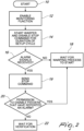
- Figure 2 shows the steps of the setup procedure according to the invention in the form of a flowchart.
- the setup procedure starts in block 10, with the warper W at rest.
- the gateway G enables the monitoring function on all the yarn feeders YF 1 , YF 2 , YF 3 , ..., YF X associated with the warper W.
- the gateway G commands the warper W to start for the setup cycle and, at the same time, disables sending the stop command STOP to the warper W if alarm signals AL are received.
- the gateway G checks to see if it has received alarm signals AL.
- the gateway G waits for the warping process to start.
- the gateway G sends the stop command STOP to the warper W and in block 20 it asks for permission to disable the monitoring function on the yarn feeders that sent the alarm messages.
- the gateway G awaits verification by the user.
- the setup procedure according to the invention fully achieves the set aims, in that it makes it possible to identify, in a few seconds, which yarn feeders are not involved in a weaving process and to simultaneously disable the monitoring function on those yarn feeders, and all without requiring any modification to the textile machine.
- the duration of the setup cycle can be determined by a programmed stop of the textile machine.
- this embodiment can be advantageously implemented in cases where the textile machine is programmed to execute, before the processing, a threading cycle at the end of which it stops automatically. If the duration of the threading cycle is sufficient to detect the unwinding of yarn on each one of the yarn feeders, the setup cycle can be integrated in the threading cycle executed by the textile machine.
- the gateway will learn from the status signal when the threading cycle has reached its end, and as a consequence will interrupt the setup cycle as well.
- the steps of the setup procedure after the stop command is sent may vary based on the preferences of the user.
- the gateway could disable the monitoring function on all the feeders that sent the alarm signal, without asking the user for permission (block 20 in Figure 2 ).
- the gateway does ask for permission and the user does not give it within a preset time, or expressly denies it (e.g., by sending a specific command)
- the setup procedure could be interrupted instead of remaining on standby while awaiting verification (block 22 in Figure 2 ).
- gateway and the associated graphical user interface are illustrated as self-contained devices, obviously the gateway could be integrated in the textile machine and, as a consequence, the graphical user interface could be incorporated in a control panel of the textile machine.
- the monitoring function can be advantageously disabled simultaneously on all the selected yarn feeders, as an alternative it can be disabled in sequence on all the selected yarn feeders or on successive groups of yarn feeders in which that function is disabled simultaneously.
Landscapes
- Engineering & Computer Science (AREA)
- Quality & Reliability (AREA)
- Manufacturing & Machinery (AREA)
- Physics & Mathematics (AREA)
- General Physics & Mathematics (AREA)
- Automation & Control Theory (AREA)
- Human Computer Interaction (AREA)
- General Engineering & Computer Science (AREA)
- Filamentary Materials, Packages, And Safety Devices Therefor (AREA)
Applications Claiming Priority (1)
| Application Number | Priority Date | Filing Date | Title |
|---|---|---|---|
| IT202300006780 | 2023-04-06 |
Publications (1)
| Publication Number | Publication Date |
|---|---|
| EP4443252A1 true EP4443252A1 (de) | 2024-10-09 |
Family
ID=86942169
Family Applications (1)
| Application Number | Title | Priority Date | Filing Date |
|---|---|---|---|
| EP24167372.2A Pending EP4443252A1 (de) | 2023-04-06 | 2024-03-28 | Aufbauverfahren zur gleichzeitigen konfiguration einer vielzahl von elektronisch gesteuerten garnliefervorrichtungen in einem textilverfahren |
Country Status (2)
| Country | Link |
|---|---|
| EP (1) | EP4443252A1 (de) |
| CN (1) | CN118771098A (de) |
Citations (5)
| Publication number | Priority date | Publication date | Assignee | Title |
|---|---|---|---|---|
| EP3098340A1 (de) * | 2015-05-20 | 2016-11-30 | L.G.L. Electronics S.p.A. | Verfahren zur meldung kritischer ereignisse an mit einer vielzahl von fäden gespeisten textilmaschinen |
| WO2017115242A1 (en) * | 2015-12-30 | 2017-07-06 | Btsr International S.P.A. | Method for detecting and remotely managing sensors and/or devices for feeding textile and/or metallic yarns installed on one or more textile machines, and system thereof |
| EP3293595A1 (de) * | 2016-09-13 | 2018-03-14 | Premier Evolvics PVT. Ltd. | Integriertes system und verfahren zur online-überwachung und offline-prüfung in einer textilen einheit |
| US20190177108A1 (en) * | 2017-12-08 | 2019-06-13 | Saurer Fibrevision Ltd. | Method and system for monitoring drawing of yarn from a bobbin |
| EP3699343A1 (de) * | 2019-02-25 | 2020-08-26 | Memminger-IRO GmbH | Verfahren und system zur überwachung der produktion einer strickmaschine mit mehreren fadenliefergeräten |
-
2024
- 2024-03-25 CN CN202410344463.3A patent/CN118771098A/zh active Pending
- 2024-03-28 EP EP24167372.2A patent/EP4443252A1/de active Pending
Patent Citations (5)
| Publication number | Priority date | Publication date | Assignee | Title |
|---|---|---|---|---|
| EP3098340A1 (de) * | 2015-05-20 | 2016-11-30 | L.G.L. Electronics S.p.A. | Verfahren zur meldung kritischer ereignisse an mit einer vielzahl von fäden gespeisten textilmaschinen |
| WO2017115242A1 (en) * | 2015-12-30 | 2017-07-06 | Btsr International S.P.A. | Method for detecting and remotely managing sensors and/or devices for feeding textile and/or metallic yarns installed on one or more textile machines, and system thereof |
| EP3293595A1 (de) * | 2016-09-13 | 2018-03-14 | Premier Evolvics PVT. Ltd. | Integriertes system und verfahren zur online-überwachung und offline-prüfung in einer textilen einheit |
| US20190177108A1 (en) * | 2017-12-08 | 2019-06-13 | Saurer Fibrevision Ltd. | Method and system for monitoring drawing of yarn from a bobbin |
| EP3699343A1 (de) * | 2019-02-25 | 2020-08-26 | Memminger-IRO GmbH | Verfahren und system zur überwachung der produktion einer strickmaschine mit mehreren fadenliefergeräten |
Also Published As
| Publication number | Publication date |
|---|---|
| CN118771098A (zh) | 2024-10-15 |
Similar Documents
| Publication | Publication Date | Title |
|---|---|---|
| EP2031106B1 (de) | Verfahren zur Spannungskontrolle eines Garnes, das von einem negativen Liefergerät an eine Textilmaschine geliefert wird, und Vorrichtung zur Durchführung des Verfahrens | |
| CN101223094B (zh) | 用于确保恒定张力纱线喂入纺织机械的双控制回路方法和装置 | |
| US8397582B2 (en) | Method for detecting the stop of the yarn unwinding from a yarn feeder provided with a stationary drum | |
| CN102373574A (zh) | 用于检测编织线上纱线意外停止的方法与装置 | |
| CN106245212B (zh) | 控制从累积供料机向纺织机解绕纱的消耗速率方法及装置 | |
| TWI619860B (zh) | 紗線饋送系統 | |
| US20130327877A1 (en) | Tension-controlling method for a yarn unwinding from a storage yarn feeder to a textile machine | |
| US20240409357A1 (en) | Self-synchronizing yarn tension monitoring and control system | |
| JPS5947063B2 (ja) | たて編機 | |
| CN118771098A (zh) | 用于在纺织工艺中同时配置多个电子控制的纱线供给器的设置方法 | |
| EP3230510A1 (de) | Verfahren und vorrichtung zur überwachung einer strickmaschine | |
| CN101268001A (zh) | 操作生产交叉卷绕筒子的纺纱机的工位的方法 | |
| EP3763650B1 (de) | Verfahren zum zuführen mehrerer fäden zu einer textilmaschine über jeweils positive fadenzufürvorrichtungen | |
| JP2005514533A (ja) | 糸処理システムを制御および/またはモニターする装置ならびに方法 | |
| EP4474325B1 (de) | Selbstsynchronisierendes system zur überwachung und steuerung der fadenspannung | |
| EP1184493B1 (de) | Motorsteuerungssystem für Textilmaschinen mit Einzelspindelantrieb | |
| JP3006562B2 (ja) | 糸巻取機の停電処理システム | |
| CN111607891B (zh) | 带有多个供线器的用于监控针织机的生产的方法和系统 | |
| EP1391983B1 (de) | Verfahren zur Feststellung der Motorblockierung des Vorförderers des Schussfaden-Vordosierers in Webmaschinen | |
| JPH0423019B2 (de) | ||
| CN107620154A (zh) | 用于控制纱线从纬纱喂纱器退绕的方法 | |
| JP2005239295A (ja) | 繊維機械の設定装置 | |
| EP2631339B1 (de) | Garnzuführungsvorrichtungen mit geregelter Spannung für Textilmaschinen, mit Garnrückgewinnungsfunktion | |
| EP3098340A1 (de) | Verfahren zur meldung kritischer ereignisse an mit einer vielzahl von fäden gespeisten textilmaschinen | |
| JPS60167861A (ja) | 自動ワインダ−の制御方法 |
Legal Events
| Date | Code | Title | Description |
|---|---|---|---|
| PUAI | Public reference made under article 153(3) epc to a published international application that has entered the european phase |
Free format text: ORIGINAL CODE: 0009012 |
|
| STAA | Information on the status of an ep patent application or granted ep patent |
Free format text: STATUS: THE APPLICATION HAS BEEN PUBLISHED |
|
| AK | Designated contracting states |
Kind code of ref document: A1 Designated state(s): AL AT BE BG CH CY CZ DE DK EE ES FI FR GB GR HR HU IE IS IT LI LT LU LV MC ME MK MT NL NO PL PT RO RS SE SI SK SM TR |
|
| STAA | Information on the status of an ep patent application or granted ep patent |
Free format text: STATUS: REQUEST FOR EXAMINATION WAS MADE |
|
| 17P | Request for examination filed |
Effective date: 20241105 |
|
| RBV | Designated contracting states (corrected) |
Designated state(s): AL AT BE BG CH CY CZ DE DK EE ES FI FR GB GR HR HU IE IS IT LI LT LU LV MC ME MK MT NL NO PL PT RO RS SE SI SK SM TR |
|
| GRAP | Despatch of communication of intention to grant a patent |
Free format text: ORIGINAL CODE: EPIDOSNIGR1 |
|
| STAA | Information on the status of an ep patent application or granted ep patent |
Free format text: STATUS: GRANT OF PATENT IS INTENDED |
|
| RIC1 | Information provided on ipc code assigned before grant |
Ipc: G05B 19/409 20060101AFI20260108BHEP Ipc: G05B 19/418 20060101ALI20260108BHEP |
|
| INTG | Intention to grant announced |
Effective date: 20260119 |
|
| P01 | Opt-out of the competence of the unified patent court (upc) registered |
Free format text: CASE NUMBER: UPC_APP_0003162_4443252/2026 Effective date: 20260129 |
|
| GRAS | Grant fee paid |
Free format text: ORIGINAL CODE: EPIDOSNIGR3 |