EP4443709A1 - Magnetmodul für einen rotor einer elektrischen maschine - Google Patents
Magnetmodul für einen rotor einer elektrischen maschine Download PDFInfo
- Publication number
- EP4443709A1 EP4443709A1 EP23166835.1A EP23166835A EP4443709A1 EP 4443709 A1 EP4443709 A1 EP 4443709A1 EP 23166835 A EP23166835 A EP 23166835A EP 4443709 A1 EP4443709 A1 EP 4443709A1
- Authority
- EP
- European Patent Office
- Prior art keywords
- base member
- rotor
- recess
- magnet
- house
- Prior art date
- Legal status (The legal status is an assumption and is not a legal conclusion. Google has not performed a legal analysis and makes no representation as to the accuracy of the status listed.)
- Withdrawn
Links
Images



Classifications
-
- H—ELECTRICITY
- H02—GENERATION; CONVERSION OR DISTRIBUTION OF ELECTRIC POWER
- H02K—DYNAMO-ELECTRIC MACHINES
- H02K1/00—Details of the magnetic circuit
- H02K1/06—Details of the magnetic circuit characterised by the shape, form or construction
- H02K1/22—Rotating parts of the magnetic circuit
- H02K1/27—Rotor cores with permanent magnets
- H02K1/2706—Inner rotors
- H02K1/272—Inner rotors the magnetisation axis of the magnets being perpendicular to the rotor axis
- H02K1/274—Inner rotors the magnetisation axis of the magnets being perpendicular to the rotor axis the rotor consisting of two or more circumferentially positioned magnets
- H02K1/2753—Inner rotors the magnetisation axis of the magnets being perpendicular to the rotor axis the rotor consisting of two or more circumferentially positioned magnets the rotor consisting of magnets or groups of magnets arranged with alternating polarity
- H02K1/278—Surface mounted magnets; Inset magnets
-
- F—MECHANICAL ENGINEERING; LIGHTING; HEATING; WEAPONS; BLASTING
- F03—MACHINES OR ENGINES FOR LIQUIDS; WIND, SPRING, OR WEIGHT MOTORS; PRODUCING MECHANICAL POWER OR A REACTIVE PROPULSIVE THRUST, NOT OTHERWISE PROVIDED FOR
- F03D—WIND MOTORS
- F03D9/00—Adaptations of wind motors for special use; Combinations of wind motors with apparatus driven thereby; Wind motors specially adapted for installation in particular locations
- F03D9/20—Wind motors characterised by the driven apparatus
- F03D9/25—Wind motors characterised by the driven apparatus the apparatus being an electrical generator
-
- H—ELECTRICITY
- H02—GENERATION; CONVERSION OR DISTRIBUTION OF ELECTRIC POWER
- H02K—DYNAMO-ELECTRIC MACHINES
- H02K1/00—Details of the magnetic circuit
- H02K1/06—Details of the magnetic circuit characterised by the shape, form or construction
- H02K1/22—Rotating parts of the magnetic circuit
- H02K1/27—Rotor cores with permanent magnets
-
- H—ELECTRICITY
- H02—GENERATION; CONVERSION OR DISTRIBUTION OF ELECTRIC POWER
- H02K—DYNAMO-ELECTRIC MACHINES
- H02K1/00—Details of the magnetic circuit
- H02K1/06—Details of the magnetic circuit characterised by the shape, form or construction
- H02K1/22—Rotating parts of the magnetic circuit
- H02K1/27—Rotor cores with permanent magnets
- H02K1/2786—Outer rotors
- H02K1/2787—Outer rotors the magnetisation axis of the magnets being perpendicular to the rotor axis
- H02K1/2789—Outer rotors the magnetisation axis of the magnets being perpendicular to the rotor axis the rotor consisting of two or more circumferentially positioned magnets
- H02K1/2791—Surface mounted magnets; Inset magnets
-
- H—ELECTRICITY
- H02—GENERATION; CONVERSION OR DISTRIBUTION OF ELECTRIC POWER
- H02K—DYNAMO-ELECTRIC MACHINES
- H02K1/00—Details of the magnetic circuit
- H02K1/06—Details of the magnetic circuit characterised by the shape, form or construction
- H02K1/22—Rotating parts of the magnetic circuit
- H02K1/28—Means for mounting or fastening rotating magnetic parts on to, or to, the rotor structures
-
- H—ELECTRICITY
- H02—GENERATION; CONVERSION OR DISTRIBUTION OF ELECTRIC POWER
- H02K—DYNAMO-ELECTRIC MACHINES
- H02K21/00—Synchronous motors having permanent magnets; Synchronous generators having permanent magnets
- H02K21/12—Synchronous motors having permanent magnets; Synchronous generators having permanent magnets with stationary armatures and rotating magnets
-
- H—ELECTRICITY
- H02—GENERATION; CONVERSION OR DISTRIBUTION OF ELECTRIC POWER
- H02K—DYNAMO-ELECTRIC MACHINES
- H02K7/00—Arrangements for handling mechanical energy structurally associated with dynamo-electric machines, e.g. structural association with mechanical driving motors or auxiliary dynamo-electric machines
- H02K7/18—Structural association of electric generators with mechanical driving motors, e.g. with turbines
- H02K7/1807—Rotary generators
- H02K7/1823—Rotary generators structurally associated with turbines or similar engines
- H02K7/183—Rotary generators structurally associated with turbines or similar engines wherein the turbine is a wind turbine
-
- H—ELECTRICITY
- H02—GENERATION; CONVERSION OR DISTRIBUTION OF ELECTRIC POWER
- H02K—DYNAMO-ELECTRIC MACHINES
- H02K2201/00—Specific aspects not provided for in the other groups of this subclass relating to the magnetic circuits
- H02K2201/03—Machines characterised by aspects of the air-gap between rotor and stator
-
- H—ELECTRICITY
- H02—GENERATION; CONVERSION OR DISTRIBUTION OF ELECTRIC POWER
- H02K—DYNAMO-ELECTRIC MACHINES
- H02K2213/00—Specific aspects, not otherwise provided for and not covered by codes H02K2201/00 - H02K2211/00
- H02K2213/03—Machines characterised by numerical values, ranges, mathematical expressions or similar information
-
- Y—GENERAL TAGGING OF NEW TECHNOLOGICAL DEVELOPMENTS; GENERAL TAGGING OF CROSS-SECTIONAL TECHNOLOGIES SPANNING OVER SEVERAL SECTIONS OF THE IPC; TECHNICAL SUBJECTS COVERED BY FORMER USPC CROSS-REFERENCE ART COLLECTIONS [XRACs] AND DIGESTS
- Y02—TECHNOLOGIES OR APPLICATIONS FOR MITIGATION OR ADAPTATION AGAINST CLIMATE CHANGE
- Y02E—REDUCTION OF GREENHOUSE GAS [GHG] EMISSIONS, RELATED TO ENERGY GENERATION, TRANSMISSION OR DISTRIBUTION
- Y02E10/00—Energy generation through renewable energy sources
- Y02E10/70—Wind energy
- Y02E10/72—Wind turbines with rotation axis in wind direction
Definitions
- the present invention relates to a magnet module for a rotor of an electrical machine, relates to a rotor for an electrical machine and further relates to an electrical machine, in particular wind turbine generator.
- the permanent magnets mounted on the rotor are housed within a magnet module.
- the magnet module may be mounted to the rotor house, for example using a "T-track" retention system. Thereby, the radial and circumferential or tangential movement of the magnet module may be constrained by structural features machined for example at or into the rotor house.
- a generator with multiple stator sections supplying parallel converters may have only selected sections of the stator active or operating under certain operating conditions such as under reduced converter operation (RCO) and the forces on the magnet module, as it transitions from active to inactive segments/sectors of the stator, may cause more complex transient module torques and forces. Those forces or torques may overcome the frictional forces and may allow the magnet module to move (slide or lift) within the retention system of the rotor house. This may conventionally lead to so-called "module rattling" which may cause nuisance noise but more importantly may also lead to issues of fatigue of the retention structure due to the module repeatedly impacting on the rotor house structure. In the past, these conventionally observed magnet module movements may have limited the operational envelope in modes where only limited sections of the stator are active.
- RCO reduced converter operation
- a magnet module for a rotor of an electrical machine there may be a need for a rotor for an electrical machine and there may be a need for an electrical machine, wherein some of the above-mentioned disadvantages are reduced or even overcome. Further, there may be a need for improvements of firm mounting of a magnet module to a rotor, where undesired movements and noise may be reduced or even avoided whilst having limited negative impact on the main rotor torque.
- a magnet module for a rotor of an electrical machine comprising: a base member extending in a width direction, in particular circumferential direction, in a length direction, in particular axial direction, and in a thickness direction, in particular radial direction, and having a rotor house contact/mounting surface and, at an opposite side, a magnet contact/mounting surface both extending in the width direction and the length direction; a magnet mounted at the magnet mounting surface of the base member, wherein the base member has at least one first base member recess at the rotor house mounting surface, the first base member recess extending in the length direction.
- the magnet module may, beside the base member and the magnet, also comprise a cover which covers the magnet and which may be welded to the base member.
- the cover may protect the magnet from damage and/or corrosion.
- the base member may substantially be configured as a rectangular plate and the magnet may also have a rectangular cross section (when viewed along the width direction or radial direction) .
- the width direction, the length direction and the thickness direction may be associated or attributed to the magnet module for itself.
- the circumferential direction, the axial direction and the radial direction made to the respective directions when the magnet module is installed at the rotor to which a rotation axis running in the axial direction can be attributed.
- a circumferential direction and a radial direction can be attributed which are both perpendicular to the axial direction in the conventional sense.
- the rotor house mounting surface may be and/or the magnet mounting surface may be substantially plane, flat surfaces, in particular having rectangular shape.
- the respective mounting surfaces may be machined surfaces. There may or there may not be any material in between or cover on the rotor house mounting surfaces and/or the magnet mounting surface when the magnet module is mounted to the rotor and the magnet is mounted to the base member, in particular mounted to the magnet mounting surface of the base member.
- An interface between the magnet and the base member may e.g. consist or comprise an adhesive layer or bondline.
- Any gap between the rotor house and the rotor house mounting surface of the magnet module may be minimized or may be kept below a given threshold. The same holds for any gap between the magnet mounting surface of the magnet module and a mounting surface of the magnet.
- the magnet may - for mounting - comprise a base member mounting surface which may also be substantially a flat, plane surface, in particular machined surface.
- the (first) base member recess may also be referred to as base member slit or base plate slit.
- the first/second base member recess may substantially or primarily extend in the length direction of the magnet module, corresponding in an assembled state to the axial direction (of the rotor or the electrical machine).
- the first/second base member recess may act as a magnetic flux barrier, causing flux lines to be deformed and being led around the first/second base member recess. Thereby, radial forces pulling the magnet module towards the rotor house may be increased resulting in increased stability of the magnet module when assembled or mounted to the rotor house.
- the positioning along the width direction of the first/second base member recess may be determined or defined based on the particular application, in particular including performing simulations of the resulting magnetic fluxes or forces and/or torques acting on the magnet module when placed or arranged at the rotor house, in particular at the mounting areas or at a particular mounting area.
- the base member recess may also be considered as a base member cavity.
- the base member recess may be open to the or towards the rotor house mounting surface.
- the recess may or may not house a non-magnetic and/or non-conductive medium, such as air or any other suitable fluid or solid material.
- the introduction of the at least first base member recess (and in particular also a second base member recess) into the base member may enhance the performance of the resulting or assembled electrical machine or assembled rotor, as the retention force(s) or attractive force(s) of the mounting of the magnet module to the rotor may be improved. Further, in particular, the addition of the first and/or second base member recess may further improve the performance or the effects of any potentially present rotor house recess or slit.
- the magnet module may consist of a permanent magnet bonded onto a ferromagnetic base plate which may have a thickness of for example between 3 mm and 7 mm, in particular around 5 mm.
- the magnet may be covered with a metallic cover which may be located over the magnet and which may be welded to the base plate in order to fully encapsulate the magnet and for example to prevent corrosion and prevent damage.
- the base plate or in general the base member may typically have a machined surface or machined surfaces to better control the dimensions of "tabs" which locate within the rotor house retainment system and to ensure the base plate flatness, to minimize “parasitic” air gaps between the base plate and the rotor house in the main magnet flux path or magnetic circuit of the magnet.
- the first base member recess opens towards the rotor house mounting surface and/or wherein the magnet protrudes in the thickness or radial direction from the base member; and/or wherein the base member is configured as base plate.
- manufacturing the first and/or second base member recess may be simplified and flux lines may be deformed to increase attractive forces.
- the base member recess(es) may for example be manufactured by a milling or machining or grinding process or an EDM erosion process, for example.
- the base member including the first and/or second base member recess may be a cast piece or may be produced by casting or for example by additive manufacturing.
- the base member has a second base member recess at the rotor house mounting surface spaced apart from the first base member recess in the width direction, the second base member recess extending in the length direction, in particular parallel to the first base member recess.
- the presence of a second base member recess may further increase in particular radial forces acting on the magnet module when assembled to a rotor for increasing the fixation or attachment of the mounting. Thereby, undesired movements and/or noise due to the magnet module may be reduced.
- the first and/or the second base member recesses may be substantially parallel to the length direction of the magnet module or may be parallel to the axial direction of the assembled rotor or assembled electrical machine. Thereby, also the manufacturing may be simplified.
- the base member comprises at width direction ends, in particular circumferential ends, edges which extend in the length direction, the edges being provided to engage with a retention structure at a rotor house, and/or wherein the first and/or second base member recess at least partially extends parallel to the edges.
- Edges may be utilized to engage with a conventionally known retention structure, in particular a rail structure. Edges may for example comprise cross-sectional shapes being complementary to one half of a "T" when the retention structure is provided with “T” shaped rails extending in the axial direction. Thereby, conventionally available rotors may be utilized for mounting the magnet module to the rotor.
- the base member recess has an axial extent or extent in the length direction of between 50% and 100% of an extent of the base member in the length direction, and/or wherein the base member recess has a circumferential extent or extent in the width direction of between 1% and 10% or 15% of an extent of the base member in the width direction, and/or wherein the base member recess has a radial extent or extent in the thickness direction of between 10% and 100%, in particular between 40% and 80%, of an extent of the base member in the thickness direction.
- the respective dimensions or extents may be selected or determined based on the particular application.
- the respective dimensions may for example be derived from simulations of magnetic fluxes and/or forces and/or torques and also simulations regarding the structural stability of the components.
- the base member recess is formed by several base member recess portions being separated from each other in the length direction, the base member recess portions having equal or different shape and/or extent.
- the portions in between may serve to increase the mechanical rigidity or stability of the base member. Thereby, the base member may be prohibited from bending or bending may be reduced.
- a rotor for an electrical machine, in particular wind turbine generator comprising: at least one magnet module according to any one of the preceding embodiments; a rotor house having a rotation axis along an axial direction and having plural magnet module mounting areas spaced apart in the circumferential direction and extending in the axial and the circumferential direction, the rotor house having a rotor house recess at at least one of the magnet module mounting areas, wherein the magnet module is arranged at the at least one of the magnet module mounting areas having the rotor house recess.
- the rotor may be an outer rotor or an inner rotor.
- the rotor house may have substantially a cylinder symmetry, the symmetry axis being parallel or coinciding with the axial direction.
- the rotor house recess may also be referred to as rotor house slit or rotor house cut-out.
- the rotor house recess may open towards the magnet module mounting area and may be in particular within the magnet module mounting area to which the magnet module comprising at least the first and/or a second base member recess is mounted.
- first base member recess and/or the second base member recess may advantageously deform the magnetic flux lines (around the respective recesses) potentially or advantageously causing higher radial forces pulling or pushing the magnet module towards the rotor house.
- the combination of the presence of the rotor house recess with the presence of the first base member recess and/or the second base member recess may advantageously deform the magnetic flux lines (around the respective recesses) potentially or advantageously causing higher radial forces pulling or pushing the magnet module towards the rotor house.
- any movements or "rattling" of the magnet module attached to the rotor house may be reduced or even avoided thereby improving performance.
- the rotor house recess may be considered as a cut-out machined within the rotor house.
- the rotor house recess or cut-out may act in the following ways:
- the rotor house comprises plural retention rails, in particular providing insertion slots, spaced apart in the circumferential direction and extending in the axial direction, wherein the magnet module mounting areas are provided between two adjacent retention rails, respectively, wherein the two edges, of the base member of the magnet module, extending in the length direction are inserted between two adjacent retention rails, wherein the retention rails have in particular T-shape.
- the retention rails may substantially have a cross-sectional shape as a "T". Between each pair of two adjacent retention rails, an insertion slot may be provided into which one or more magnet modules may be inserted along the axial direction.
- the rotor may for example have mounted five and ten magnet modules between each of two retention rails, for example. Thereby, conventional mounting systems for mounting magnet modules may be utilized.
- the rotor house recess of the rotor house is circumferentially arranged between the first base member recess and the second base member recess of the base member and/or wherein a circumferential spacing between the first and/or the second base member recess and the rotor house recess is between 1% and 5% of the width extent of the base member.
- the magnetic flux lines may advantageously be concentrated in areas between the rotor house recess and the first/second base member recess, in order to increase magnetic flux density and hence increase radial forces pulling the magnet module towards the rotor house.
- the exact relative positioning of the first/second base member recess and the rotor house recess may be determined from simulations.
- the rotor house recess has an axial extent corresponding to a total axial extent of plural magnet modules arranged between the two adjacent retention rails, axially behind each other or spaced apart, wherein the rotor house recess has a circumferential extent between 10% and 40% of a width extent of the base member, and/or wherein the rotor house recess has a radial extent of between 5% and 40% of a radial extent of the rotor house.
- the rotor house recess has an area size of a cross section taken perpendicular to the axial direction of 5 to 20 times an area size of a cross section of the first and/or second base member recess.
- the rotor house recess may be substantially larger in cross-sectional area than any of the first and/or second base member recesses.
- the relatively larger area of the rotor house recess may be possible due to the relatively larger extent of the rotor house wall thickness into which the rotor house recess may be provided or machined relative to the thickness of the base member of the magnet module.
- the base member recess and/or the rotor house recess has in cross section, perpendicular to the axial direction, at least in partially, a rectangular shape, in particular with sharp or rounded or radiused or filleted corners, a triangular shape, a V-shape, or a U-shape, and/or wherein the rotor house recess and/or the first and/or second base member recess is filled with air or glue or epoxy or other non-magnetic filler such as plastic or composite.
- the different cross-sectional shapes may provide different effects which may relate to performance and/or stability and may be selected based on the particular application. Thereby, great flexibility is provided.
- the respective shape may also be selected based on the available manufacturing technologies or ease of manufacturing.
- an electrical machine in particular wind turbine generator, comprising: a stator with stator windings; a rotor according to one of the preceding embodiments, rotatably supported with respect to the stator.
- the stator may for example be a segmented or a non-segmented stator.
- the stator may be a segmented stator comprising of plural stator segments each segment providing a segment of a circumferential ring portion, for example spanning 30°, 45°, 60°, 90°, 120° or another value.
- Each stator segment may be provided with an individual (multi-phase) stator winding set which may be connected to an associated converter.
- the machine may comprise plural converters to which the respective stator windings of the different stator segments are connected.
- the electrical machine may for example also be configured to operate in a reduced converter operational mode, in which one or more of the stator windings of one or more of the stator segments are non-operational and also the connected converters are non-operational.
- a reduced converter operational mode in which one or more of the stator windings of one or more of the stator segments are non-operational and also the connected converters are non-operational.
- embodiments of the present invention may provide significant advantages with respect to undesired rattling of magnet modules or movement of magnet modules.
- one of the two edges extending in the axial direction being a leading edge of the base member with respect to the rotation direction, the other of the two edges extending in the axial direction being a trailing edge of the base member with respect to the rotation direction, wherein the first and/or second base member recess is at a position along the width direction or circumferential direction closer to the leading edge than to the trailing edge, where in particular a pivot point or pivot line is located, wherein the machine is in particular one of: an integer slot distributed winding permanent magnet synchronous machine, or a fractional slot concentrated winding permanent magnet synchronous machine.
- the first and second base member recesses may not be provided for example in a centre region between the two edges extending in the axial direction but may be shifted or offset towards one side or one circumferential side or side in the width direction of the magnet module.
- the magnet module may pivot or rotate or rattle around a pivot point or pivot line which is at the circumferential end (in particular edge) into which the magnet module is pushed due to the rotation. Pivoting or rattling about or around this pivot point may be reduced according to embodiments of the present invention.
- a method of manufacturing a magnet module for a rotor of an electrical machine, in particular a wind turbine generator comprising: providing a base member extending in a width direction, in a length direction, and in a thickness direction, with a rotor house contact/mounting surface and, at an opposite side, a magnet contact/mounting surface both extending in the width direction and the length direction; mounting a magnet at the magnet mounting surface of the base member, providing at least one first base member recess at the rotor house mounting surface of the base member.
- the portion of an electrical machine 100 schematically illustrated in Fig. 1 in a cross-sectional view along an axial direction 101 (being perpendicular to a radial direction 102 and also being perpendicular to a circumferential direction 103) comprises a stator 104 with stator windings 105, as provided between teeth 106. Further, the electrical machine 100 comprises a rotor 110 according to an embodiment of the present invention.
- the rotor 110 comprises at least one magnet module 130 according to an embodiment of the present invention.
- the rotor 110 further comprises a rotor house 111 having a rotation axis 112 (illustrated in Fig. 1 but in reality at the centre of the rotor being farther away from the rotor house 111 vertically shifted downwards).
- the rotation axis 112 is along the axial direction 101.
- the rotor house has plural magnet module mounting areas 113a, 113b, 113c of which in Fig. 1 only one mounting area 113a is shown completely.
- the different magnet module mounting areas 113a, 113b, 113c are spaced apart in the circumferential direction 103 and extend in the axial direction 101 as well as in the circumferential direction 103.
- the respective magnet module mounting areas 113a, 113b, 113c each comprises respective mounting surfaces 114a,b,c, in particular providing contact surfaces of magnet modules to be mounted.
- the rotor house 111 has a rotor house recess 115 at least one of the magnet module mounting areas 113a.
- a magnet module 130 according to an embodiment of the present invention is arranged. Examples of embodiments of the magnet module 130 will be explained with reference to the following figures.
- the rotor house 111 comprises plural retention rails 116 which provide insertion slots in between wherein the retention rails 116 are spaced apart in the circumferential direction 103 and extend in the axial direction 101.
- the magnet module mounting areas 113a, 113b, 113c are provided between two adjacent retention rails 116, respectively.
- Two edges 131 of a base member 132 of the magnet module 130 which extend in the length direction (parallel to the axial direction 101) are inserted between two adjacent retention rails 116.
- the retention rails 116 have a "T"-shape.
- the magnet module 130 is an example of a magnet module for a rotor of an electrical machine according to an embodiment of the present invention.
- the magnet module 130 comprises a base member 132 which extends in a width direction corresponding to the circumferential direction 103.
- the base member 132 further extends in a length direction corresponding to the axial direction 101 and in a thickness direction corresponding to the radial direction 102.
- the base member 132 has a rotor house mounting surface 133 and, at an opposite side, a magnet mounting surface 134, wherein both these mounting surfaces 133, 134 extend in the width direction 103 as well as in the length direction 101.
- a magnet 135 is mounted at the magnet mounting surface 134 of the base member 132.
- the magnet 135 is covered by a protection cover 136 which is optional.
- the base member 132 has at least one first base member recess 137 at the rotor house mounting surface 133.
- the first base member recess 137 extends primarily in the length direction corresponding to the axial direction 101. As can be appreciated from Fig. 1 , the first base member recess 137 opens towards the rotor house mounting surface 133 of the base member 132.
- the magnet 135 extends/protrudes in the thickness or radial direction (corresponding to the radial direction 102) from the base member 132.
- the base member 132 is configured as a base plate.
- the base member 132 comprises a second base member recess 138 (which is optional) at the rotor house mounting surface 133 spaced apart from the first base member recess 137 in the width direction 103. Also the second base member recess 138 extends in the length direction 101.
- the base member 132 comprises at width direction ends, in particular circumferential ends, the edges 131 which extend in the length direction 101, wherein the edges 131 are provided to engage with retention structure 116 at the rotor house 111.
- the rotor house recess 115 of the rotor house 111 is circumferentially (i.e. along the circumferential direction 103) arranged between the first base member recess 137 and the second base member recess 138 of the base member 132.
- the cross-sectional view of Fig. 1 also illustrates that the rotor house recess 115 has an area size of a cross section taken perpendicular to the axial direction 101 of 5 to 20 times an area size of a cross section of the first and/or the second base member recess 137, 138.
- the base member recesses 137, 138 as well as the rotor house recess 115 have a rectangular shape with relatively sharp edges. In other embodiments, other shapes may be provided, for example the shapes illustrated in Figs. 10 to 13 .
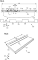
- Fig. 2 illustrates in a schematic three-dimensional view a base member 232 of a magnet module according to an embodiment of the present invention, in particular viewed from above the side in contact with the rotor house.
- the base member 232 comprises the rotor house mounting surface 233 at which the first and the second base member recesses 237, 238 are provided.
- the base member recesses 237, 238 extend in the full axial length 'al' of the base member 232.
- the respective recesses may be cut out or machined starting at the axial face of the module and travelling axially along the full length of the magnet module or full length of the base member 232 in the axial direction 201.
- the magnet module base member 132 illustrated in Fig. 1 may be for example configured as is illustrated in Fig. 2 .
- Figs. 3 and 4 illustrate magnetic flux lines in a comparative example and an embodiment of an electrical machine according to an embodiment of the present invention, respectively. It can be appreciated from Fig. 4 that the magnetic flux as derived by simulation is locally increased at regions labelled with reference signs 440. The increased magnetic flux density results in an increased radial force pulling the respective magnet module 430 towards the rotor house 411. The increased magnetic flux densities are due to both the base member recesses 437, 438 as well as due to the rotor house recess 415.
- Fig. 5 illustrates in geometrical or cross-sectional view another embodiment 500 of an electrical machine according to an embodiment of the present invention.
- the first base member recess 537 has an extent in the width direction or circumferential direction 503 of ce, has an extent re in the radial direction 502.
- the first base member recess 537 is spaced apart from the second base member recess 538 by the separation distance rs.
- the first and second base member recesses 537, 538 are spaced apart by the amount rc from a centre line cl of the rotor house recess 515.
- the particular dimensions rc, rs, cl, ce, re, sw may be determined or selected based on the particular application, for example derived based on simulations.
- Fig. 6 illustrates a base member 632 of a magnet module according to another embodiment of the present invention.
- the respective magnet module may for example be utilized in a rotor and/or an electrical machine according to an embodiment of the present invention.
- the respective first base member recess 637 and the second base member recess 638 do not extend along the full axial length al of the base member 632 but are provided only in a central portion extending about between 80% and 95% of the axial length al of the base member 632. This may have the advantage of reducing the impact that the base member recess has on the base member rigidity.
- the respective base member recesses 637, 638 may either go fully through the entire base member 632 or they may only partly go through the base member 632 in the thickness direction 602 corresponding to the radial direction.
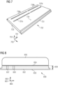
- the respective base member recesses are formed by several base member recess portions 737a, 737b and 738a, 738b which are separated from each other in the length direction 701. Thereby, further, the rigidity of the base member 732 may be improved. Also this base member 732 may be employed for any magnet module according to embodiments of the present invention.
- the magnet module 830 illustrated in Fig. 8 in a cross-sectional view according to an embodiment of the present invention also comprises a first base member recess 837 in a base member 832 and a second base member recess 838.
- the respective recesses 837, 838 go through the full depth of the base member, i.e. have a radial extent in the radial direction 802 or width direction which is 100% of the radial extent 839 of the base member 832.
- Fig. 9 schematically illustrates in a cross-sectional view a portion of an electrical machine 900 according to an embodiment of the present invention.
- the base member 932 of the magnet module 930 comprises a first base member recess 937 and a second base member recess 938 which have different circumferential separation 940, 941 from the rotor house recess 915.
- the separation relative to the rotor house recess 915 is thereby asymmetric with respect to the width direction 903 or circumferential direction.
- the different separations 940, 941 may for example be derived based on simulations of the flux.
- the different recesses in the base member 932 may have different widths and/or depths.
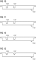
- Figs. 10 to 13 illustrate embodiments of base members 1032, 1132, 1232, 1332 of magnet modules according to embodiments of the present invention for example be provided in one or more or all of the previously illustrated embodiments of a rotor or an electrical machine according to embodiments of the present invention.
- the first as well as the second base member recesses 1037, 1038 have a rectangular shape in cross section, in Fig. 11 , a rectangular shape with rounded or radiused corners.
- the recesses 1237, 1238 have fileted or angles internal corners and the shapes of the base member recesses 1337, 1338 illustrated in Fig. 13 have a triangular shape or V-shape.
- Figs. 10 to 13 may be employed according to previously illustrated or described embodiments. Thereby, for example, mechanical strength may be improved or stress concentration may be avoided further manufacturing may be simplified.
- two slits are introduced in the base plate of a magnet module, separated by a width which is greater than the rotor house recess or rotor house slit preferably located on the same central axis of the rotor house slit as illustrated in Fig. 1 .
- Additional slits 137, 138 may act to enhance the flux concentration caused by the accompanying rotor house slit 115 and may create localized regions of higher magnetic flux as illustrated in Fig. 4 .
- the module radial force may be enhanced and a torque about the module pivot point 151 (see Fig. 1 , where rotor rotation direction during normal operation is to the left) may be created.
- the slits 137, 138 in the base member 132 do not have to extent into the full depth of the base plate or base member 132 such that it maintains its structure integrity and required stiffness (for example they may be 3 mm deep within a 5 mm base plate thickness).
- Base plate slits may typically be 1 mm - 6 mm wide, with 3 mm depth for example.
- Resulting overlap (quantity sw illustrated in Fig. 5 ) regions/zones may be controlled by the separation of the base plate slits relative to the rotor house slit width.
- the overlap (sw shown in Fig. 5 ) may for example amount to about 6 mm.
- Overlap may be dimensioned such that the force is not sensitive to any circumferential movement of the base plate within the T-track which would result in an asymmetric overlap.
- a second base member recess is an optional feature according to an embodiment of the present invention.
- Embodiments of the present invention provide also enhancement of fatigue lifetime of a fixation glue which is utilized to fixate a magnet to a base plate or base member.
Landscapes
- Engineering & Computer Science (AREA)
- Power Engineering (AREA)
- Life Sciences & Earth Sciences (AREA)
- Sustainable Development (AREA)
- Sustainable Energy (AREA)
- Chemical & Material Sciences (AREA)
- Combustion & Propulsion (AREA)
- Mechanical Engineering (AREA)
- General Engineering & Computer Science (AREA)
- Permanent Field Magnets Of Synchronous Machinery (AREA)
Priority Applications (5)
| Application Number | Priority Date | Filing Date | Title |
|---|---|---|---|
| EP23166835.1A EP4443709A1 (de) | 2023-04-05 | 2023-04-05 | Magnetmodul für einen rotor einer elektrischen maschine |
| KR1020257025995A KR20250130669A (ko) | 2023-04-05 | 2024-03-13 | 전기 기계의 회전자용 자석 모듈 |
| PCT/EP2024/056682 WO2024208552A1 (en) | 2023-04-05 | 2024-03-13 | Magnet module for a rotor of an electrical machine |
| CN202480014712.0A CN120770107A (zh) | 2023-04-05 | 2024-03-13 | 用于电机的转子的磁体模块 |
| EP24712019.9A EP4635053A1 (de) | 2023-04-05 | 2024-03-13 | Magnetmodul für einen rotor einer elektrischen maschine |
Applications Claiming Priority (1)
| Application Number | Priority Date | Filing Date | Title |
|---|---|---|---|
| EP23166835.1A EP4443709A1 (de) | 2023-04-05 | 2023-04-05 | Magnetmodul für einen rotor einer elektrischen maschine |
Publications (1)
| Publication Number | Publication Date |
|---|---|
| EP4443709A1 true EP4443709A1 (de) | 2024-10-09 |
Family
ID=85979818
Family Applications (2)
| Application Number | Title | Priority Date | Filing Date |
|---|---|---|---|
| EP23166835.1A Withdrawn EP4443709A1 (de) | 2023-04-05 | 2023-04-05 | Magnetmodul für einen rotor einer elektrischen maschine |
| EP24712019.9A Pending EP4635053A1 (de) | 2023-04-05 | 2024-03-13 | Magnetmodul für einen rotor einer elektrischen maschine |
Family Applications After (1)
| Application Number | Title | Priority Date | Filing Date |
|---|---|---|---|
| EP24712019.9A Pending EP4635053A1 (de) | 2023-04-05 | 2024-03-13 | Magnetmodul für einen rotor einer elektrischen maschine |
Country Status (4)
| Country | Link |
|---|---|
| EP (2) | EP4443709A1 (de) |
| KR (1) | KR20250130669A (de) |
| CN (1) | CN120770107A (de) |
| WO (1) | WO2024208552A1 (de) |
Citations (5)
| Publication number | Priority date | Publication date | Assignee | Title |
|---|---|---|---|---|
| US20130270954A1 (en) * | 2010-09-08 | 2013-10-17 | Siemens Aktiengesellschaft | Rotor for an electrical machine |
| EP3490109A1 (de) * | 2017-11-23 | 2019-05-29 | Siemens Gamesa Renewable Energy A/S | Permanentmagnetträger eines permanentmagnetgenerators |
| CN109995163A (zh) * | 2019-04-22 | 2019-07-09 | 新疆金风科技股份有限公司 | 磁极模块、磁轭、转子和电机 |
| CN113014011A (zh) * | 2019-12-20 | 2021-06-22 | 新疆金风科技股份有限公司 | 基板、磁极模块、转子、转子的制造方法及永磁电机 |
| US20230084226A1 (en) * | 2020-02-03 | 2023-03-16 | Siemens Gamesa Renewable Energy A/S | Magnet system for a rotor and permanent magnet electrical machine |
-
2023
- 2023-04-05 EP EP23166835.1A patent/EP4443709A1/de not_active Withdrawn
-
2024
- 2024-03-13 CN CN202480014712.0A patent/CN120770107A/zh active Pending
- 2024-03-13 WO PCT/EP2024/056682 patent/WO2024208552A1/en not_active Ceased
- 2024-03-13 KR KR1020257025995A patent/KR20250130669A/ko active Pending
- 2024-03-13 EP EP24712019.9A patent/EP4635053A1/de active Pending
Patent Citations (5)
| Publication number | Priority date | Publication date | Assignee | Title |
|---|---|---|---|---|
| US20130270954A1 (en) * | 2010-09-08 | 2013-10-17 | Siemens Aktiengesellschaft | Rotor for an electrical machine |
| EP3490109A1 (de) * | 2017-11-23 | 2019-05-29 | Siemens Gamesa Renewable Energy A/S | Permanentmagnetträger eines permanentmagnetgenerators |
| CN109995163A (zh) * | 2019-04-22 | 2019-07-09 | 新疆金风科技股份有限公司 | 磁极模块、磁轭、转子和电机 |
| CN113014011A (zh) * | 2019-12-20 | 2021-06-22 | 新疆金风科技股份有限公司 | 基板、磁极模块、转子、转子的制造方法及永磁电机 |
| US20230084226A1 (en) * | 2020-02-03 | 2023-03-16 | Siemens Gamesa Renewable Energy A/S | Magnet system for a rotor and permanent magnet electrical machine |
Also Published As
| Publication number | Publication date |
|---|---|
| CN120770107A (zh) | 2025-10-10 |
| EP4635053A1 (de) | 2025-10-22 |
| WO2024208552A1 (en) | 2024-10-10 |
| KR20250130669A (ko) | 2025-09-02 |
Similar Documents
| Publication | Publication Date | Title |
|---|---|---|
| CN102751799B (zh) | 永磁型同步旋转电机用转子和旋转电机 | |
| US9525313B2 (en) | Coil tooth assembly | |
| CN101165991B (zh) | 永磁磁阻电旋转机 | |
| JP5059614B2 (ja) | 永久磁石埋め込み型ロータにおける磁石およびウエブの構成 | |
| EP2216883B1 (de) | Rotor für eine rotierende elektrische maschine | |
| US6956312B2 (en) | Brushless DC motor and method of manufacturing brushless DC motor | |
| EP1860755A2 (de) | Magnetaufnahmevorrichtung | |
| JP2004254496A (ja) | モータ用ロータアセンブリ、モータ用ステータアセンブリ、永久磁石型モータ、およびモータ | |
| US7535146B2 (en) | Brushless synchronous machine with embedded permanent magnets and trapezoidal electromagnetic force | |
| CN103580423A (zh) | 永磁激励的同步电机的转子 | |
| KR20070033037A (ko) | 전기 기계 | |
| US10170949B2 (en) | Rotating electric machine | |
| EP4443709A1 (de) | Magnetmodul für einen rotor einer elektrischen maschine | |
| JP4324821B2 (ja) | 永久磁石電動機 | |
| JP5039482B2 (ja) | リラクタンスモータ用回転子積層鉄心 | |
| CN213693262U (zh) | 一字型不对称分段永磁同步电机转子 | |
| CN201352733Y (zh) | 转子磁钢具有梯形槽结构的永磁电机 | |
| CN118589725A (zh) | 转子冲片、转子、电机和车辆 | |
| CN103715800B (zh) | Ipm型旋转电动机 | |
| JP7507840B2 (ja) | 回転電機、回転電動機駆動システム、並びに電動車両 | |
| CN213585322U (zh) | V字型不对称分段永磁同步电机转子 | |
| CN106816976A (zh) | 转子冲片、电机转子及永磁同步电机 | |
| JP5679695B2 (ja) | 永久磁石式回転電機 | |
| EP3748817A1 (de) | Permanentmagnetmodul für eine permanentmagnetmaschine | |
| JP2023042025A (ja) | 回転子 |
Legal Events
| Date | Code | Title | Description |
|---|---|---|---|
| PUAI | Public reference made under article 153(3) epc to a published international application that has entered the european phase |
Free format text: ORIGINAL CODE: 0009012 |
|
| STAA | Information on the status of an ep patent application or granted ep patent |
Free format text: STATUS: THE APPLICATION HAS BEEN PUBLISHED |
|
| AK | Designated contracting states |
Kind code of ref document: A1 Designated state(s): AL AT BE BG CH CY CZ DE DK EE ES FI FR GB GR HR HU IE IS IT LI LT LU LV MC ME MK MT NL NO PL PT RO RS SE SI SK SM TR |
|
| STAA | Information on the status of an ep patent application or granted ep patent |
Free format text: STATUS: THE APPLICATION IS DEEMED TO BE WITHDRAWN |
|
| 18D | Application deemed to be withdrawn |
Effective date: 20250410 |