EP4443752A1 - Système de communication filaire pour remplacer un bus can/lin embarqué - Google Patents
Système de communication filaire pour remplacer un bus can/lin embarqué Download PDFInfo
- Publication number
- EP4443752A1 EP4443752A1 EP24163272.8A EP24163272A EP4443752A1 EP 4443752 A1 EP4443752 A1 EP 4443752A1 EP 24163272 A EP24163272 A EP 24163272A EP 4443752 A1 EP4443752 A1 EP 4443752A1
- Authority
- EP
- European Patent Office
- Prior art keywords
- terminal
- communication units
- main control
- communication unit
- communication system
- Prior art date
- Legal status (The legal status is an assumption and is not a legal conclusion. Google has not performed a legal analysis and makes no representation as to the accuracy of the status listed.)
- Pending
Links
Images


Classifications
-
- H—ELECTRICITY
- H04—ELECTRIC COMMUNICATION TECHNIQUE
- H04B—TRANSMISSION
- H04B3/00—Line transmission systems
- H04B3/54—Systems for transmission via power distribution lines
- H04B3/544—Setting up communications; Call and signalling arrangements
-
- H—ELECTRICITY
- H04—ELECTRIC COMMUNICATION TECHNIQUE
- H04L—TRANSMISSION OF DIGITAL INFORMATION, e.g. TELEGRAPHIC COMMUNICATION
- H04L27/00—Modulated-carrier systems
- H04L27/26—Systems using multi-frequency codes
- H04L27/2601—Multicarrier modulation systems
- H04L27/2647—Arrangements specific to the receiver only
- H04L27/2655—Synchronisation arrangements
-
- H—ELECTRICITY
- H04—ELECTRIC COMMUNICATION TECHNIQUE
- H04B—TRANSMISSION
- H04B3/00—Line transmission systems
- H04B3/54—Systems for transmission via power distribution lines
- H04B3/548—Systems for transmission via power distribution lines the power on the line being DC
-
- B—PERFORMING OPERATIONS; TRANSPORTING
- B60—VEHICLES IN GENERAL
- B60R—VEHICLES, VEHICLE FITTINGS, OR VEHICLE PARTS, NOT OTHERWISE PROVIDED FOR
- B60R16/00—Electric or fluid circuits specially adapted for vehicles and not otherwise provided for; Arrangement of elements of electric or fluid circuits specially adapted for vehicles and not otherwise provided for
- B60R16/02—Electric or fluid circuits specially adapted for vehicles and not otherwise provided for; Arrangement of elements of electric or fluid circuits specially adapted for vehicles and not otherwise provided for electric constitutive elements
- B60R16/023—Electric or fluid circuits specially adapted for vehicles and not otherwise provided for; Arrangement of elements of electric or fluid circuits specially adapted for vehicles and not otherwise provided for electric constitutive elements for transmission of signals between vehicle parts or subsystems
-
- H—ELECTRICITY
- H04—ELECTRIC COMMUNICATION TECHNIQUE
- H04B—TRANSMISSION
- H04B1/00—Details of transmission systems, not covered by a single one of groups H04B3/00 - H04B13/00; Details of transmission systems not characterised by the medium used for transmission
- H04B1/38—Transceivers, i.e. devices in which transmitter and receiver form a structural unit and in which at least one part is used for functions of transmitting and receiving
- H04B1/3822—Transceivers, i.e. devices in which transmitter and receiver form a structural unit and in which at least one part is used for functions of transmitting and receiving specially adapted for use in vehicles
-
- H—ELECTRICITY
- H04—ELECTRIC COMMUNICATION TECHNIQUE
- H04B—TRANSMISSION
- H04B3/00—Line transmission systems
- H04B3/02—Details
- H04B3/46—Monitoring; Testing
-
- H—ELECTRICITY
- H04—ELECTRIC COMMUNICATION TECHNIQUE
- H04B—TRANSMISSION
- H04B3/00—Line transmission systems
- H04B3/54—Systems for transmission via power distribution lines
-
- H—ELECTRICITY
- H04—ELECTRIC COMMUNICATION TECHNIQUE
- H04L—TRANSMISSION OF DIGITAL INFORMATION, e.g. TELEGRAPHIC COMMUNICATION
- H04L27/00—Modulated-carrier systems
- H04L27/26—Systems using multi-frequency codes
- H04L27/2601—Multicarrier modulation systems
-
- H—ELECTRICITY
- H04—ELECTRIC COMMUNICATION TECHNIQUE
- H04L—TRANSMISSION OF DIGITAL INFORMATION, e.g. TELEGRAPHIC COMMUNICATION
- H04L27/00—Modulated-carrier systems
- H04L27/26—Systems using multi-frequency codes
- H04L27/2601—Multicarrier modulation systems
- H04L27/2602—Signal structure
-
- H—ELECTRICITY
- H04—ELECTRIC COMMUNICATION TECHNIQUE
- H04L—TRANSMISSION OF DIGITAL INFORMATION, e.g. TELEGRAPHIC COMMUNICATION
- H04L27/00—Modulated-carrier systems
- H04L27/32—Carrier systems characterised by combinations of two or more of the types covered by groups H04L27/02, H04L27/10, H04L27/18 or H04L27/26
- H04L27/34—Amplitude- and phase-modulated carrier systems, e.g. quadrature-amplitude modulated carrier systems
-
- H—ELECTRICITY
- H04—ELECTRIC COMMUNICATION TECHNIQUE
- H04L—TRANSMISSION OF DIGITAL INFORMATION, e.g. TELEGRAPHIC COMMUNICATION
- H04L5/00—Arrangements affording multiple use of the transmission path
- H04L5/003—Arrangements for allocating sub-channels of the transmission path
-
- H—ELECTRICITY
- H04—ELECTRIC COMMUNICATION TECHNIQUE
- H04L—TRANSMISSION OF DIGITAL INFORMATION, e.g. TELEGRAPHIC COMMUNICATION
- H04L7/00—Arrangements for synchronising receiver with transmitter
- H04L7/0016—Arrangements for synchronising receiver with transmitter correction of synchronization errors
- H04L7/0033—Correction by delay
- H04L7/0037—Delay of clock signal
-
- H—ELECTRICITY
- H04—ELECTRIC COMMUNICATION TECHNIQUE
- H04B—TRANSMISSION
- H04B2203/00—Indexing scheme relating to line transmission systems
- H04B2203/54—Aspects of powerline communications not already covered by H04B3/54 and its subgroups
- H04B2203/5404—Methods of transmitting or receiving signals via power distribution lines
- H04B2203/5425—Methods of transmitting or receiving signals via power distribution lines improving S/N by matching impedance, noise reduction, gain control
-
- H—ELECTRICITY
- H04—ELECTRIC COMMUNICATION TECHNIQUE
- H04B—TRANSMISSION
- H04B2203/00—Indexing scheme relating to line transmission systems
- H04B2203/54—Aspects of powerline communications not already covered by H04B3/54 and its subgroups
- H04B2203/5429—Applications for powerline communications
-
- H—ELECTRICITY
- H04—ELECTRIC COMMUNICATION TECHNIQUE
- H04B—TRANSMISSION
- H04B2203/00—Indexing scheme relating to line transmission systems
- H04B2203/54—Aspects of powerline communications not already covered by H04B3/54 and its subgroups
- H04B2203/5462—Systems for power line communications
Definitions
- This disclosure relates to a new wired communication system to replace the architecture mainly based on a CAN/LIN bus in a vehicle, to decrease the cost and improve the practicability of automated production.
- the associated method may also be applied to wired communication applications such as an in-vehicle power line, a twisted pair, a coaxial cable and the like.
- ITO Internet of things
- CAN controller area network
- LIN local interconnect network
- these wiring harnesses have the high material cost, increase the weight of the vehicle, decrease the effective space in the vehicle, and cannot be easily adapted to the automation assembling and on-line upgrading. So, if the in-vehicle power line or the fewer wiring harnesses can be used as the in-vehicle transmission line functioning to achieve the in-vehicle communication, then it is possible to advantageously decrease the cost, decrease the overall weight of the system, increase the effective space in the vehicle, upgrade the automotive software easily, and facilitate the automated production.
- PLC power line communication
- G3-PLC Generation 3rd PLC
- HPLC High Speed PLC
- Homplug AV/GreenPhy communication modes transmission is performed using fixed frequency bands, wherein only one of communication units on the same transmission line is allowed to transmit the signal onto the transmission line at the same time instant, or otherwise the so-called signal "collision" occurs to cause signal errors and the signal needs to be transmitted again.
- the existing PLC communication mode cannot guarantee that the signal transmission certainly succeeds at one time, and the existing PLC communication mode has the possibility of error occurrence, and cannot guarantee the time of successfully completing the transmission. Because the in-vehicle communication usually requires the real-time property and the reliability, the existing PLC communication protocol is less applicable to the replacement of the reliable CAN/LIN for completing the transmission.
- a frequency-division multiplexing (FDM) method is previously and frequently used to divide the used frequency band into several frequency bands.
- FDM frequency-division multiplexing
- a certain guard band is reserved between the frequency bands in order to avoid the interference between the adjacent frequency bands and ensure the isolation between the frequency bands.
- the configuration needs to discard some frequency bands functioning as the guard bands.
- the ratio of the discarded frequency bands becomes unignorable, and the full use of precious and limited communication frequency bands cannot be achieved.
- various analog and digital filters are added to the hardware design of the communication unit of each frequency band, thereby increasing the system cost and power consumption.
- a fixed used frequency band may be configured for each communication unit.
- an embodiment of this disclosure can divide the frequency band without the needs of the guard band and the additional filter, and the embodiment of this disclosure is also different from the common FDM device, which only demodulates its own dedicated frequency band upon demodulation. Instead, the embodiment of this disclosure demodulates the frequency bands used by all the communication units, and the packet lengths outputted from all the communication units are the same.
- This disclosure proposes a wired communication system for replacing an in-vehicle CAN/LIN bus.
- the wired communication system has a power line or a transmission line coupled to multiple communication units.
- wires such as a twisted pair, a coaxial cable and the like may also be used to replace the power line in order to obtain the better communication quality.
- the wired communication system includes a main control communication unit for performing a time delay or attenuation value calibration on the communication units and completing clock calibration.
- the main control communication unit and the communication units perform time synchronization.
- the main control communication unit allocates multiple transmission frequency bands used by the communication units, and adjusts transmission energies of the communication units, so that attenuations of the transmission energies of the communication units corresponding to the transmission frequency bands obtain proper or corresponding compensations. In some cases, compensations of attenuation amounts may also be completed by way of receiving terminal compensations.
- the main control communication unit allocates the communication units, so that the communication units have an uplink time or a downlink time corresponding to the transmission frequency bands.
- the communication units when the time delay and the attenuation value are greater than a threshold value, after the main control communication unit has allocated the uplink time of the communication units corresponding to the transmission frequency band, the communication units concurrently transmit the one packet to the main control communication unit, and the main control communication unit forwards the packet to the target communication units.
- the main control communication unit coordinates the transmitting time of each communication unit and calibrates the clock, so that the packet synchronization when the packets of each of the communication units are transmitted to the main control communication unit is improved, or the better demodulation effects are obtained through the receiving terminal of the system for correcting the individual frequency band angle.
- the main control communication unit makes the communication units compensate for the signal energy thereof in advance before transmitting the packet according to positions of the communication units on the power line, or the attenuation value of the signal, so that signal energy levels in all of the transmission frequency bands are substantially the same when the target communication units receive the packet.
- the receiving terminal in the system may also complete partial or full compensation to demodulate the correct signal contents.
- the main control communication unit is configured such that the overall system has different communication units that can be used in a mixed manner to decrease the overall system cost.
- This disclosure proposes several architectures that can be used in the in-vehicle wired communication, in which the wires such as the twisted pair or the coaxial cable is also applicable, and the wires do not play the role of supplying the power, are not connected to the battery, and are purely used in the communication.
- the architecture is applicable to the transmission line application having the short distance, the lower noise and the smaller online impedance variation.
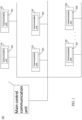
- FIG. 1 is a schematic view showing an embodiment of this disclosure.
- a wired communication system 100 of this disclosure for replacing an in-vehicle CAN/LIN bus includes a main control communication unit 1 and multiple application modules 101 to 10N, which have corresponding communication units 201 to 20N, respectively.
- the wired communication system 100 has a transmission line coupled to the communication units 201 to 20N.
- the wired communication system 100 is a non-PLC system.
- the frequency bands that can be transmitted by the communication units 201 to 20N are different from one another.
- the communication units 201 to 20N are allocated with different transmission frequency bands B1 to BN, so that the signal collision problem is not present in this disclosure.
- the system may be regarded as the same OFDM system when the attenuation degrees and the time delays of the signals received at arbitrary positions of the power line or the transmission line approach each other (e.g., the variation is smaller than a threshold value).
- the frequency bands that can be transmitted by the communication units are constituted by some specific sub-carriers that are not repeated, and the system only needs to synchronize times and packet lengths of the signals transmitted by the communication units, so that the communication units can concurrently transmit the signals to the individual dedicated frequency bands, and also receive signals outputted from all the communication units and perform packet demodulation at the same time. That is, there is no overlap present between the transmission frequency bands of the communication units, no overlap is present between the transmission frequency bands of the communication units and the transmission frequency band of the main control communication unit, and no overlap is present between transmission times between the communication units and a transmission time of the main control communication unit. All of the transmission frequency bands can be combined into a complete OFDM frequency band, and there is no guard band between the transmission frequency bands.
- each communication module can demodulate transmission contents of other communication units, the communication mode thereof is a "many-to-many" mode.
- the receiver can realize that the message is to be transmitted to itself and perform the corresponding processing.
- any communication unit also realizes the message contents to be exchanged between other communication units. For a highly intelligent self-driving system in the future, this characteristic of using such the message transmission method is very efficient, and any operation unit can dominate the messages of other sensors in a real-time manner or realize the reactions performed by other operation units. Illustrations will be described with reference to a following simple example.
- each communication unit is allocated with a dedicated frequency band with four sub-carriers for transmitting the signal. In this manner, each communication unit can output the signal to other communication units through its own dedicated frequency band.
- the communication units 201, 205, 2010 and 2016 output the packets within a specific packet time, and the communication unit 208 is the transmission target of the communication units 201 and 205.
- the communication unit 2010 transmits the packet to the communication unit 2016, and the communication unit 2016 broadcasts the packet to all the other communication units.
- the communication unit 208 receives the packets coming from the communication units 201 and 205, and the communication unit 2016 receives the message from the communication unit 2010.
- all the communication units 201 to 2015 receive the packet(s) from the communication unit 2016. Because each communication unit demodulates all the packets outputted onto the power line, each communication unit may also realize all the packets therebetween.
- the main control communication unit may be any one of the communication units 201 to 2016, the communication unit is in charge of coordinating the communication start, and each of the communication units 201 to 2016 can synchronously transmit and receive signals in the communication process.
- each of the communication units 201 to 20N can transmit and receive signals concurrently.
- the starting time and the ending time of transmitting the packet by each of the communication units 201 to 20N needs to be synchronized upon demodulation at the receiving terminal, so that the correct packet can be demodulated. That is, the system of this disclosure needs to have the synchronization process after booting up, and needs to hold this synchronization and continuously perform the proper fine tuning to compensate the influence of external factors, such as the temperature humidity and the like, upon the normal operation.
- the main control communication unit needs to keep all the communication units continuously synchronizing with the clock itself, and the main control communication unit and the communication units concurrently output the packets having the same length, so that all signals are always kept at the states that can be demodulated by each communication unit and the main control communication unit.
- the main control communication unit is the object to which all the communication units transmit the messages.
- the communication unit farther from the main control communication unit starts to transmit the packet earlier, and the communication unit closer to the main control communication unit starts to transmit the packet later.
- the OFDM signals received by the main control communication unit are as if all the transmission frequency bands are concurrently outputted from a certain communication unit, and the demodulation can be performed smoothly.
- the main control communication unit adjusts the transmitting terminals of all the communication units in the system to perform the time delay calibration, so that all the packets, which are outputted from the communication units and reach the main control communication unit, can be combined into a complete OFDM signal.
- the message transmission becomes that the communication units transmit signals to the main control communication unit in one period of time, and that the main control communication unit transmits messages to all the communication units in another period of time. That is, the signals between the communication units are differentiated in a FDM manner, and the signals between each of the communication units and the main control communication unit are differentiated in a time-division multiplexing (TDM) manner to prevent collision.
- TDM time-division multiplexing
- the main control communication unit 1 performs a time delay or attenuation value calibration on the communication units 201 to 20N, so that all the communication units 201 to 20N are time-synchronized; the main control communication unit 1 also allocates the transmission frequency bands used by the communication units 201 to 20N; and the main control communication unit 1 adjusts the transmission energies of the communication units 201 to 20N so that energy values of the transmission energies of the communication units 201 to 20N have been calibrated when the corresponding transmission frequency bands B1 to BN reach the main control communication unit 1; or the receiving terminal in the system performs the self compensation so that the messages of all the communication units 201 to 20N can be demodulated smoothly.
- the vehicle message sharing has the advantage, and the corresponding reaction can be made earlier.
- the main control communication unit 1 allocates the communication units 201 to 20N, so that the communication units 201 to 20N have an uplink time of the transmission frequency bands B1 to BN for transmitting a packet.
- the communication units 201 to 20N After the main control communication unit 1 has allocated the uplink time of the communication units 201 to 20N corresponding to the transmission frequency bands B1 to BN, the communication units 201 to 20N concurrently transmit packets to the main control communication unit 1, which allocates the downlink time, and transmits the packets to the communication units 201 to 20N at the downlink time.
- the communication units 201 to 20N concurrently transmit their individual packets to the main control communication unit 1 at the uplink time, the main control communication unit 1 demodulates the packets, outputted from all the communication units 201 to 20N, into a complete OFDM signal, and the main control communication unit 1 transmits the packets to the communication units 201 to 20N at the downlink time.
- the main control communication unit 1 when the main control communication unit 1 is transmitting the packet, the communication units 201 to 20N is in a receiving state; and when the communication units 201 to 20N are transmitting the packets, the main control communication unit 1 is in the receiving state.
- FIG. 2 is a schematic view showing the initial startup of the wired communication system 100 of this disclosure.
- the communication units 201 to 20N have different frequency bands and transmit different powers at this time.
- the main control communication unit 1 makes each of the communication units 201 to 20N perform energy compensation in advance, so that the energy levels of all the communication frequency bands are consistent when the receiving terminal of the system receives the signals.
- FIG. 3 it is assumed that there are sixteen communication units 201 to 2016 that can message one another on the same power line, and each communication unit is allocated with a dedicated frequency band of four sub-carriers for transmitting the signal.
- FIG. 3 shows the communication unit 20N having the consistent energy level in the overall communication frequency band.
- the attenuation calibration may also be compensated by the receiving terminal of the main control communication unit 1.
- the above-mentioned concept can be extended to other complex or hybrid modes.
- multiple communication units may use the same frequency band in a time-division manner in some application modules (e.g., light dimming or car window lift control) which are less sensitive to the time delay. Consequently, a larger bandwidth may be reserved and used by the communication unit having the big data amount or the high immediate requirement in the system.
- the wired communication system 100 is in a second time domain. At this time, in addition to the main control communication unit in the system, other communication units may perform communications using the full frequency band (or the whole transmission frequency band).
- each camera transmits the image in a TDM manner by allocating the time to let the data be transmitted back to the main control communication unit, and the OFDM modulation and demodulation abilities of the low bandwidth communication unit connected to the lamp control or car window control can be downgraded. That is, the OFDM signal processing accuracy and efficiency of the low bandwidth communication unit can be decreased to reduce the cost of the overall system.
- 1,024 different discrete states can be transmitted in each signal cycle, and the system is connected to 4 full-band high-speed communication units and 128 low-speed communication units.
- Each low-speed communication unit only can modulate and demodulate continuous 16 sub-carriers, and each sub-carrier can resolve only 64 QAM.
- the main control communication unit can configure: a first packet time for the transmission of the main control communication unit; second to fifth packet times for 4 high-speed communication units to perform alternate transmission (256 sub-carriers can be outputted, and each sub-carrier can solve 1,024 QAM); a sixth packet time allocated to 16 low-speed communication units each being specified to use continuous 16 sub-carriers without repetition; and analogically seventh to thirteenth packet times specified to be used by 16 low-speed communication units without repetition. That is, 128 low-speed communication units are allocated to finish the message transmission once alternately in 8 packet times, and then it turns to the main control communication unit that transmits the message, and the processes are repeated in such a manner.
- the packet time of the low-speed communication unit is interspersed in the packet times used by the main control communication unit and the high-speed communication unit, and each communication unit has its own dedicated and fixed transmission frequency band and message amount.
- the sub-carrier modulation ability of the low-speed communication unit is equal to only 64 QAM, the requirement on the signal-to-noise ratio (SNR) of the transmitted signal is lower, which means that the reliability is higher.
- SNR signal-to-noise ratio
- its demodulation ability is equal to only 16 sub-carriers. So, when the main control communication unit needs to transmit the message to the low-speed communication unit, the message needs to be placed in its configured sub-carrier and 8 bits of the most significant bit (MSB).
- MSB most significant bit
- FIG. 4A is a schematic view showing a wired communication system 400A for replacing an in-vehicle CAN/LIN bus according to an embodiment of this disclosure.
- a low-pass filter F also needs to be connected between the battery BA and the power line.
- the main objective thereof is to guarantee that the higher attenuation of the signal cannot be caused in the communication frequency band signal due to the low impedance of the battery BA and the power consumption unit, and to block the noise, generated by the power consumption unit, from entering the trunk power line.
- the wired communication system 400A is a system, in which the power line is used.
- the ground wire of the vehicle is generally replaced by the car shell, the DC electricity is generally supplied from the power cable (line) to each application module, and then the DC electricity flows back to the battery from the car-shell ground wire nearby.
- the network signal is also transmitted in the same loop, then the signal tends to radiate, and the external interference noise is also absorbed by the transmission line. So, it is more proper that the differential signal is transmitted using the cable such as the twist pair. That is, the DC current loop still inherits from the original car shell loop, but the network signal flows back through the twisted-pair loop.
- the differential signal transmission line can be used to serve as the same set of DC power cables or two sets of power cables (e.g., one cable of 3.3V, and the other cable of 24V), and the requirement on the power chip on each application module can be properly reduced.
- the resistor serially connected to the capacitor or the transformer is usually adopted to isolate the voltage on the power line, and to transmit and receive the full channel message, as shown in FIG. 5 .
- each of the application modules 411 to 41N of the wired communication system (power line) 400A includes power consumption units 301 to 30N and communication units 201 to 20N corresponding thereto. That is, the main control communication unit 1 of the vehicle transmits the power energy wave and network signal through the automotive power line.
- the low-pass filter 401 is disposed at the entrance of each of all or some of power consumption terminals E of the application modules 411 to 41N, and filters the network signal, so that the power energy wave enters the power consumption units 301 to 30N of the application modules 411 to 41N.
- the coupler 402 generates a coupling path P1 for bypassing the network signal without passing through the low-pass filter 401, and the network signal enters the transmission terminal T through the first coupler 402 via the coupling path P1. That is, the network signal enters the communication units 201 to 20N of the application modules 411 to 41N through the coupling path P1 generated by the coupler 402.
- the power consumption units 301 to 30N are power supply units corresponding to the communication units.
- the low-pass filter 401 is disposed at the entrance of each of all or some of the power consumption terminals E of the wired communication system 400A.
- the low-pass filter 401 separates the power line into the power consumption terminal E and the transmission terminal T, wherein the power line impedance at the side of the transmission terminal T is not affected by that at the side of the power consumption terminal E.
- FIG. 4B is a schematic view showing a wired communication system 400B of an embodiment of this disclosure for replacing an in-vehicle CAN/LIN bus.
- the wired communication system 400B is different from the wired communication system 400A in that the low-pass filter may be replaced with an active isolator 403 in this embodiment to reduce the requirement on the transformer or inductance value.
- the active isolator 403 is disposed at the entrance of each of all or some of the power consumption terminals E of the wired communication system.
- the active isolator 403 separates the power line into the power consumption terminal E and the transmission terminal T, and filters the network signal so that the power energy wave enters the power consumption terminal E, wherein other principles are the same as those mentioned hereinabove.
- FIG. 4C is a schematic view showing the active isolator 403 of an embodiment.
- the isolator of this embodiment includes two transformers K1 and K2 respectively serially connected to the power line; and two amplifiers A1 and A2 respectively coupled to the starting terminal of the primary-side coil and the starting terminal of the secondary-side coil of the transformer K1, wherein the output terminal of the amplifier A1 is coupled to the inverting input terminal of the amplifier A1, the output terminal of the amplifier A2 is coupled to the inverting input terminal of the amplifier A2, and the output terminals of the amplifiers A1 and A2 are coupled between the two transformers K1 and K2.
- the noninverting input terminals of the amplifiers A1 and A2 are respectively coupled to the starting terminal of the primary-side coil and the starting terminal of the secondary-side coil of the transformer K1.
- the power line at the high-voltage side is parallelly connected to a high-voltage capacitor C. That is, the high-voltage capacitor C is parallelly connected between the ending terminal of the primary-side coil and the ending terminal of the secondary-side coil of the transformer K2, and the power line.
- the capacitors Care parallelly connected between the starting terminal of the primary-side coil and the starting terminal of the secondary-side coil of the transformer K1, the noninverting input terminals of the amplifiers A1 and A2 and the power line, and parallelly connected between the ending terminal of the primary-side coil and the ending terminal of the secondary-side coil of the transformer K1, the inverting input terminals and the output terminals of the amplifiers A1 and A2 and the power line.
- each of the communication units 201 to 20N includes two capacitors C; and two matching resistors Rs functioning as impedance matching and being respectively serially connected to the capacitors C.
- a line driver LD is disposed between the transmitting terminal Tx of the communication unit and the matching resistors Rs, and a low-noise amplifier LNA is disposed between the receiving terminal Rx of the communication unit, the capacitors C and the matching resistors Rs.
- the matching resistors RS function as impedance matching and are respectively serially connected to the capacitors C, and the transmitting terminal Tx is parallelly connected to a switch S. When the transmitting terminal Tx is transmitting the signal, this switch S is OFF. When the transmitting terminal Tx does not transmit the signal, this switch S is ON. If N communication units are connected onto the power line, then the low frequency impedance of the transmission line is far less than that of the matching resistor, and the wavelength of the transmission frequency band is much longer than the length of the transmission line, then the signal is attenuated into 1/(N+1) times of the original level after the signal, outputted from the line driver LD on each of the communication units, has been transmitted onto the transmission line. If there are 99 communication units disposed on the power line, then the signal received by the receiving terminal Rx is equal to (1/100) times of the superimposed signal of the signals outputted from all the communication units. That corresponds to the 40dB attenuation.
- the DC electricity is generally supplied from the power cable (line) to each application module, and then flows back to the battery from the car-shell ground wire nearby. If the network signal also runs along the same loop, then the signal is easily radiated, and the external interference noise is also easily absorbed by the transmission line. So, it is proper that the differential signal is transmitted using the cable such as twist pairs. That is, the DC current loop follows the original car shell loop, but the network signal flows back through the twisted-pair loop.
- the differential signal transmission line can be used to serve as the same set of DC power cables or two sets of power cables (e.g., one cable of 3.3V, and the other cable of 24V), and the requirement on the power chip on each application module can be properly reduced.
- the communication units can directly communicate with one another through specific protocols.
- the communication units need to communicate with one another through units of transceivers concurrently having different frequency bands.
- the graft communication is performed through the main control communication unit or other regional adapter boards on the vehicle, as shown in FIG. 6.
- FIG. 6 shows the configuration, which is similar to that of FIG. 4A , and is applicable to the "one-to-many" or "many-to-many” communication mode.
- the wired communication system is coupled to the main control communication unit through different band pass filters corresponding to different transmission frequency bands.
- the band pass filters can filter the signals, having different frequency bands, into the communication units of the communication unit groups.
- the wired communication system has multiple transmission module groups corresponding to different transmission frequency bands B1 to BN, wherein the communication units, which are not in the same transmission module group, cannot directly communicate with each other, and the transmission frequency bands are also different from each other.
- the low-frequency frequency band e.g., from 100 KHz to 2 MHz
- each of the communication units 201 to 203 using this frequency band has its own dedicated transmission frequency band
- the communication units 201 to 203 can directly transmit signals to one another and perform the real-time demodulation without the forwarding through the main control communication unit. All the signals of the communication units 201 to 203 using the large frequency band are coupled to the transmission line through the band pass filters (100 KHz to 2 MHz).
- the communication units 204 to 20N using the large frequency bands need to communicate with one another through the main control communication unit.
- the entrance coupler thereof is a band pass filter (10 MHz to 100 MHz) or a high-pass filter of 10 MHz.
- a guard band needs to be reserved between two large frequency bands to prevent mutual interference, and the main control communication unit has a transceiver (not shown) capable of transceiving multiple OFDM signals.
- a low-pass filter may be disposed between different sections of the power line, and then a main control communication unit is connected thereto.
- the communication between different sections of the power line needs the forwarding through the main control communication unit in a simplest manner that the main control communication unit is divided into left, right, up and down lines, wherein the principle thereof is the same as that of FIG. 4A , and the difference resides in that they are connected to the power Vs through the low-pass filters, and the main control communication unit has four sets of communication units 20N_1 to 20N_4 connected to each section of the power line.
Landscapes
- Engineering & Computer Science (AREA)
- Signal Processing (AREA)
- Computer Networks & Wireless Communication (AREA)
- Power Engineering (AREA)
- Mechanical Engineering (AREA)
- Cable Transmission Systems, Equalization Of Radio And Reduction Of Echo (AREA)
Applications Claiming Priority (3)
| Application Number | Priority Date | Filing Date | Title |
|---|---|---|---|
| TW112109611 | 2023-03-15 | ||
| TW112117025 | 2023-05-08 | ||
| TW112121140A TWI913548B (zh) | 2023-03-15 | 2023-06-06 | 取代車內can/lin總線的有線通訊系統 |
Publications (1)
| Publication Number | Publication Date |
|---|---|
| EP4443752A1 true EP4443752A1 (fr) | 2024-10-09 |
Family
ID=90365277
Family Applications (1)
| Application Number | Title | Priority Date | Filing Date |
|---|---|---|---|
| EP24163272.8A Pending EP4443752A1 (fr) | 2023-03-15 | 2024-03-13 | Système de communication filaire pour remplacer un bus can/lin embarqué |
Country Status (4)
| Country | Link |
|---|---|
| US (1) | US20240314014A1 (fr) |
| EP (1) | EP4443752A1 (fr) |
| JP (1) | JP7805660B2 (fr) |
| KR (1) | KR20240140017A (fr) |
Citations (3)
| Publication number | Priority date | Publication date | Assignee | Title |
|---|---|---|---|---|
| EP1323246A2 (fr) * | 2000-10-04 | 2003-07-02 | Conexant Systems, Inc. | Appareil et procede de constitution de reseau pour lignes electriques |
| US20080298226A1 (en) * | 2007-06-04 | 2008-12-04 | Denso Corporation | Vehicular communication device and control information generating device |
| EP3605853A1 (fr) * | 2018-07-31 | 2020-02-05 | The Boeing Company | Maintenance sur une ligne d'alimentation auxiliaire |
Family Cites Families (2)
| Publication number | Priority date | Publication date | Assignee | Title |
|---|---|---|---|---|
| WO2007016034A2 (fr) * | 2005-07-27 | 2007-02-08 | Conexant Systems, Inc. | Gestion de largeur de bande dans un reseau d'alimentation |
| JP2012080150A (ja) * | 2009-01-15 | 2012-04-19 | Panasonic Corp | データ通信システムおよびデータ通信装置 |
-
2024
- 2024-03-13 EP EP24163272.8A patent/EP4443752A1/fr active Pending
- 2024-03-14 US US18/605,067 patent/US20240314014A1/en active Pending
- 2024-03-14 KR KR1020240036045A patent/KR20240140017A/ko active Pending
- 2024-03-14 JP JP2024040132A patent/JP7805660B2/ja active Active
Patent Citations (3)
| Publication number | Priority date | Publication date | Assignee | Title |
|---|---|---|---|---|
| EP1323246A2 (fr) * | 2000-10-04 | 2003-07-02 | Conexant Systems, Inc. | Appareil et procede de constitution de reseau pour lignes electriques |
| US20080298226A1 (en) * | 2007-06-04 | 2008-12-04 | Denso Corporation | Vehicular communication device and control information generating device |
| EP3605853A1 (fr) * | 2018-07-31 | 2020-02-05 | The Boeing Company | Maintenance sur une ligne d'alimentation auxiliaire |
Also Published As
| Publication number | Publication date |
|---|---|
| JP2024133450A (ja) | 2024-10-02 |
| KR20240140017A (ko) | 2024-09-24 |
| US20240314014A1 (en) | 2024-09-19 |
| JP7805660B2 (ja) | 2026-01-26 |
Similar Documents
| Publication | Publication Date | Title |
|---|---|---|
| CN113647130B (zh) | 交叉链路干扰测量 | |
| RU2468523C2 (ru) | Устройство связи, способ связи, модуль электронной схемы и интегральная схема | |
| JP5046345B2 (ja) | 通信装置、及び通信システム | |
| EP1986338B1 (fr) | Procédé et appareil pour communication sur ligne de distribution d'énergie | |
| US20040258141A1 (en) | Digital communication over 28VDC power line | |
| US20100034298A1 (en) | Rail vehicle internal information network device | |
| US11689296B2 (en) | On-board communication system, optical coupler, and on-board device | |
| RU2407149C2 (ru) | Способ и модем для подводной связи по линии электропередачи | |
| US8917782B2 (en) | Vehicular power line communication system | |
| US9900248B2 (en) | Subscriber station for a bus system and method for broadband can communication | |
| EP2790365A1 (fr) | Dispositif de communication, système de communication et procédé de communication | |
| EP1908222A2 (fr) | Programmation flexible de ressources dans un environnement sujet au bruit | |
| EP1814251A4 (fr) | Méthode de communication et émetteur radio | |
| US9871559B2 (en) | Motor vehicle on-board power system and method for transmitting data signals in a motor vehicle on-board power system | |
| US20240314014A1 (en) | Wired communication system for replacing in-vehicle can/lin bus | |
| US7349347B2 (en) | ASK communication device | |
| US20200274685A1 (en) | Integrated circuit with radio frequency interconnect | |
| CN107078933B (zh) | 用于通信系统的用户站和用于高数据率的基于can的通信的方法 | |
| KR101690495B1 (ko) | G.hn 기술이 적용된 액세스 네트워크의 동기화 통신 방법과 이를 이용하는 액세스 네트워크 집선장비, 액세스 네트워크 단말, 및 액세스 네트워크 시스템 | |
| TWI913548B (zh) | 取代車內can/lin總線的有線通訊系統 | |
| US11736928B2 (en) | Wireless management of modular subsystems with proxy node options | |
| JP2011135521A (ja) | 光通信装置、通信ハーネス及び通信システム | |
| CN116827384A (zh) | 取代车内can/lin总线的有线通信系统 | |
| EP3226428A1 (fr) | Dispositif et procédé de communications | |
| US20220094502A1 (en) | On-board communication system and on-board cable |
Legal Events
| Date | Code | Title | Description |
|---|---|---|---|
| PUAI | Public reference made under article 153(3) epc to a published international application that has entered the european phase |
Free format text: ORIGINAL CODE: 0009012 |
|
| STAA | Information on the status of an ep patent application or granted ep patent |
Free format text: STATUS: REQUEST FOR EXAMINATION WAS MADE |
|
| 17P | Request for examination filed |
Effective date: 20240622 |
|
| AK | Designated contracting states |
Kind code of ref document: A1 Designated state(s): AL AT BE BG CH CY CZ DE DK EE ES FI FR GB GR HR HU IE IS IT LI LT LU LV MC ME MK MT NL NO PL PT RO RS SE SI SK SM TR |