EP4446100A1 - Formvorrichtung - Google Patents
Formvorrichtung Download PDFInfo
- Publication number
- EP4446100A1 EP4446100A1 EP23168032.3A EP23168032A EP4446100A1 EP 4446100 A1 EP4446100 A1 EP 4446100A1 EP 23168032 A EP23168032 A EP 23168032A EP 4446100 A1 EP4446100 A1 EP 4446100A1
- Authority
- EP
- European Patent Office
- Prior art keywords
- moulding apparatus
- elastomer sheet
- vacuum
- moulding
- enclosing structure
- Prior art date
- Legal status (The legal status is an assumption and is not a legal conclusion. Google has not performed a legal analysis and makes no representation as to the accuracy of the status listed.)
- Withdrawn
Links
Images


Classifications
-
- B—PERFORMING OPERATIONS; TRANSPORTING
- B29—WORKING OF PLASTICS; WORKING OF SUBSTANCES IN A PLASTIC STATE IN GENERAL
- B29C—SHAPING OR JOINING OF PLASTICS; SHAPING OF MATERIAL IN A PLASTIC STATE, NOT OTHERWISE PROVIDED FOR; AFTER-TREATMENT OF THE SHAPED PRODUCTS, e.g. REPAIRING
- B29C70/00—Shaping composites, i.e. plastics material comprising reinforcements, fillers or preformed parts, e.g. inserts
- B29C70/04—Shaping composites, i.e. plastics material comprising reinforcements, fillers or preformed parts, e.g. inserts comprising reinforcements only, e.g. self-reinforcing plastics
- B29C70/28—Shaping operations therefor
- B29C70/54—Component parts, details or accessories; Auxiliary operations, e.g. feeding or storage of prepregs or SMC after impregnation or during ageing
- B29C70/544—Details of vacuum bags, e.g. materials or shape
-
- B—PERFORMING OPERATIONS; TRANSPORTING
- B29—WORKING OF PLASTICS; WORKING OF SUBSTANCES IN A PLASTIC STATE IN GENERAL
- B29C—SHAPING OR JOINING OF PLASTICS; SHAPING OF MATERIAL IN A PLASTIC STATE, NOT OTHERWISE PROVIDED FOR; AFTER-TREATMENT OF THE SHAPED PRODUCTS, e.g. REPAIRING
- B29C70/00—Shaping composites, i.e. plastics material comprising reinforcements, fillers or preformed parts, e.g. inserts
- B29C70/04—Shaping composites, i.e. plastics material comprising reinforcements, fillers or preformed parts, e.g. inserts comprising reinforcements only, e.g. self-reinforcing plastics
- B29C70/28—Shaping operations therefor
- B29C70/40—Shaping or impregnating by compression not applied
- B29C70/42—Shaping or impregnating by compression not applied for producing articles of definite length, i.e. discrete articles
- B29C70/44—Shaping or impregnating by compression not applied for producing articles of definite length, i.e. discrete articles using isostatic pressure, e.g. pressure difference-moulding, vacuum bag-moulding, autoclave-moulding or expanding rubber-moulding
- B29C70/443—Shaping or impregnating by compression not applied for producing articles of definite length, i.e. discrete articles using isostatic pressure, e.g. pressure difference-moulding, vacuum bag-moulding, autoclave-moulding or expanding rubber-moulding and impregnating by vacuum or injection
-
- B—PERFORMING OPERATIONS; TRANSPORTING
- B29—WORKING OF PLASTICS; WORKING OF SUBSTANCES IN A PLASTIC STATE IN GENERAL
- B29L—INDEXING SCHEME ASSOCIATED WITH SUBCLASS B29C, RELATING TO PARTICULAR ARTICLES
- B29L2031/00—Other particular articles
- B29L2031/08—Blades for rotors, stators, fans, turbines or the like, e.g. screw propellers
- B29L2031/082—Blades, e.g. for helicopters
- B29L2031/085—Wind turbine blades
Definitions
- a resin-infused laminated structure can be manufactured using a vacuum bag moulding process, in which the part is placed in a bag which is then sealed, or placed under a plastic sheet which is bonded on all sides to an air-tight mould or support surface. Air is then evacuated from the vacuum bag to create a vacuum which is maintained during resin infusion and curing stages.
- the vacuum bag can be provided as a sheet of extruded polymer film. Before placing the sheet over the laminate part, butyl rubber tape is applied to the mould surface, and the edge of the sheet is then pressed onto the butyl rubber tape to form an air-tight seal.
- two polymer sheets each with a separate seal, arranged so that the outer sheet maintains the vacuum in case the inner sheet fails. Both of these must be bonded to the mould surface, i.e. two butyl rubber seals are required.
- a first butyl seal is prepared on the mould table, surrounding the laminate part.
- An inner bag is then placed over the laminate part and its outer edge is pressed onto the first butyl tape to form a seal, which is then tested for air-tightness.
- a second butyl tape is applied on the mould table, surrounding the inner bag.
- An outer bag is then placed over the inner bag and its outer edge is pressed onto the second butyl tape to form a seal, which is then also tested for air-tightness.
- Curing of the resin-infused part can be accelerated by heat.
- the vacuum-bagged assembly can be placed in an oven to cure.
- the curing stage can be assisted by heating elements incorporated in the table.
- the one-sided heating can result in defects in the cured part.
- the inventive moulding apparatus is used during resin infusion and curing steps in a casting procedure. It shall be assumed that the laminate part being moulded is arranged on a moulding surface, also referred to herein as a support surface or a moulding table, and that the moulding apparatus is placed over the laminate part, so that the laminate part is enclosed in a space defined by the support table and the moulding apparatus.
- a moulding surface also referred to herein as a support surface or a moulding table
- the enclosing structure of the inventive moulding apparatus shall be understood to comprise an upper surface (which can be essentially flat), and side walls extending downward from the upper surface.
- the moulding apparatus comprises an enclosing structure dimensioned to fit over a laminate part arranged on a moulding table or support.
- the lower perimeter of the enclosing structure therefore defines an aperture.
- An elastomer sheet extends over the lower perimeter of the enclosing structure, i.e. the elastomer sheet covers the aperture defined by the lower edges of the enclosing structure.
- an inflatable seal arrangement is provided on the underside of the elastomer sheet, along its outer edge.
- the moulding apparatus further comprises an air-tight interface between the enclosing structure and the elastomer sheet, thereby defining an interior space in which a vacuum can be established in a stage preceding or following infusion and curing stages as will be explained below.
- this interior space is referred to as the lifting vacuum space of the inventive moulding apparatus.
- the elastomer sheet extends underneath the enclosing structure, the elastomer sheet covers the laminate part when the moulding apparatus is lowered onto the support surface.
- the elastomer sheet can be made of silicone rubber, for example, or any other suitable elastomer.
- the elastomer sheet can be injection moulded to comprise various surface features such as protrusions, ridges, grooves, holes, etc. Alternatively, surface features can be bonded to the elastomer sheet. One such surface feature forms part of the air-tight interface between the enclosing structure and the elastomer sheet.
- the inflatable seal arrangement on the underside of the elastomer sheet is used to form an air-tight seal between the elastomer sheet and the moulding surface during a preparatory step of a moulding procedure.
- the inflatable seal arrangement can be formed as part of the elastomer sheet or can be bonded to the elastomer sheet.
- the moulding assembly comprises a lower mould; a laminate part arranged on the lower mould; and an embodiment of the inventive moulding apparatus arranged to enclose the laminate part.
- the inventive method of casting a laminate part comprises the steps of arranging a part to be moulded on a support surface; suspending the inventive moulding apparatus above the part; securing the elastomer sheet to the part; lowering the moulding apparatus onto the support surface; establishing a vacuum in the perimeter seal vacuum space defined by the inflatable seal arrangement and the moulding surface; and connecting ports of a resin infusion assembly.
- An advantage of the invention is that the inflatable seal arrangement removes the need for butyl seals. This leads to considerable savings in time, since the time-consuming application of butyl rubber tapes and air-tightness testing steps are no longer required.
- elastomer sheet can be used multiple times, thereby drastically reducing the quantity of waste.
- reusable vacuum bag shall be understood to be synonyms in the context of the invention, and may be used interchangeably herein.
- the elastomer sheet remains attached to the enclosing structure at all times. Therefore, during preparatory stages and after completion of the curing stage, the elastomer sheet does not require any manual handling.
- the part to be moulded is an essentially elongate object.
- the cured part can be a component that will be embedded in another structure, for example the cured part can be a spar cap or "beam" of a wind turbine rotor blade.
- the spar cap of a wind turbine rotor blade can have essentially the same length as the rotor blade. For example, for a wind turbine rotor blade with a length in the order of 100 m, a spar cap may have a length approaching 100 m.
- the width of the spar cap can be in the order of 150 mm near the root end, tapering to 50 mm or less towards the tip end of the rotor blade; the height of the spar cap can be thickest near the root end, tapering towards the tip end of the rotor blade.
- the shape of the enclosing structure can have a shape that is based on the shape of the part to be moulded. In the following, without restricting the invention in any way, it may be assumed that the enclosing structure is essentially rectangular in shape.
- the enclosing structure shall be understood to be a rigid housing constructed to retain its form under vacuum.
- the terms "enclosing structure" and "rigid housing” can be used interchangeably herein.
- the rigid housing can be made of welded steel sections, for example.
- the rigid housing can be made by constructing a steel frame, cladding the frame with panels of a suitable material, and forming hermetic seals between any joints.
- the rigid housing can be manufactured as a composite structure using glass-fibre and/or carbon-fibre reinforced material.
- the rigid housing can be constructed using any combination of suitable materials.
- the mounting apparatus comprises a lifting interface or lifting structure to assist in lifting the moulding assembly into place prior to an infusion procedure, and for removing the moulding assembly off the support table after curing.
- a lifting interface can be welded to the upper surface of the rigid housing, for example.
- the lifting structure is preferably realised to distribute loads evenly during lifting, so that the enclosing structure does not deform when suspended in the air.
- the lifting interface can comprise a framework with eyelets for connecting to the hook of a crane, for example.
- the reusable vacuum bag is preferably manufactured to comprise suitable ports for connection to inlet and outlet hoses of a resin infusion apparatus. Since any such ports of the reusable vacuum bag are not directly accessible in the inventive mounting apparatus, in a preferred embodiment the enclosing structure comprises one or more access openings arranged to provide access to the interior of the enclosing structure and to any ports of the reusable vacuum bag. For example, in a preparatory stage, a technician can reach through an access opening to connect a resin hose to a suitable port of the reusable vacuum bag.
- the access openings can be closed.
- such access openings in the mounting apparatus are hermetically sealable so that air cannot enter or leave the space between the enclosing structure and the reusable vacuum bag.
- a flange projects horizontally outward. This outwardly projecting part can be referred to herein as the housing flange.
- the upper perimeter seal is an air-tight interface realised as a form-fit seal between a lower face of the enclosing structure and the upper surface of the reusable vacuum bag.
- an angular groove may be formed along the lower face of the enclosing structure, for example in the underside of the housing flange, and the reusable vacuum bag can be moulded to comprise a corresponding angular protrusion, so that these features form a tongue-and-groove form-fit seal.
- the lower perimeter seal arrangement can be realized in any suitable manner.
- the lower perimeter seal arrangement comprises at least one inflatable bead extending about the perimeter of the elastomer sheet.
- An inflatable bead shall be understood to be a hollow tubular element extending about the perimeter of the sheet on its underside.
- a inflatable bead can be formed as part of the reusable vacuum bag. Alternatively, such an inflatable bead can be realized by bonding an elastomer tube to the reusable vacuum bag.
- the inflatable seal arrangement comprises a pair of essentially parallel beads.
- One or both of these beads can be inflatable, for example the seal arrangement can comprise one inflatable bead near the outer edge of the reusable vacuum bag, and another inflatable bead arranged at a distance inward.
- the outer bead may be solid, while the inner bead is inflatable.
- the tubular elements of the perimeter lower seal arrangement can be referred to herein as perimeter seal beads or simply perimeter beads.
- the mounting apparatus comprises an air extraction means to extract air from the perimeter seal vacuum space.
- a nozzle can extend through the housing flange into the space between the perimeter beads, allowing a first vacuum pump to be connected to the perimeter seal vacuum space.
- an arrangement of clamps is preferably deployed to press the enclosing structure onto the support surface.
- the perimeter seal vacuum space is then evacuated to establish the lower seal about the perimeter of the mounting apparatus.
- the underpressure in the perimeter seal vacuum space can be in the order of 5 mbar (500 Pa), for example.
- the clamps which mechanically press the enclosing structure onto the support surface, allow the inflatable bead(s) to be inflated, for example to an overpressure in the order of 1 - 3 bar (100 - 300 kPa).
- This overpressure in turn allows a powerful vacuum to be established in the perimeter seal vacuum space, for example an underpressure as low as 5 mbar (500 Pascal) can be achieved in the perimeter seal vacuum space when the clamps are left in place.
- the method can proceed with a step of establishing a vacuum in the infusion vacuum space defined by the elastomer sheet and the moulding surface.
- the inventive moulding assembly preferably comprises a second air extraction means adapted to extract air from the infusion vacuum space.
- the reusable vacuum bag can be moulded to include one or more ports to receive a nozzle and seal arrangement, allowing a second vacuum pump to be connected to the infusion vacuum space.
- the infusion vacuum space is evacuated to establish a vacuum between the elastomer sheet and the moulding surface, i.e. in the space in which the laminate part is arranged.
- the underpressure in the infusion vacuum space can be 5 mbar (500 Pa) or lower. A favourably low underpressure can be achieved if the clamps remain in place about the enclosing structure.
- the underpressure has the effect of pulling the reusable vacuum bag tightly against the laminate part and against the moulding table (to avoid damage to the elastomer sheet, the outer edges of the laminate part can be rounded).
- the method can then proceed with the resin infusion step.
- the reusable vacuum bag is preferably formed to comprise one or more resin inlet ports and resin outlet ports to allow resin to be drawn through the laminate part.
- An inlet hose can extend from a resin reservoir through an access port in the enclosing structure to a resin inlet port.
- an outlet hose can extend from a resin outlet port through another access port of the enclosing structure.
- the resin infusion procedure can comprise steps of preparing the resin components by heating and de-gassing and then mixing the resin components; filling the feed lines and then assisting the resin (by the vacuum underpressure) to fill the flow channels, the flow mesh, and all layers of the dry fibre laminate.
- the resin reaches one or more outlets and can be extracted in any suitable manner.
- the previously established lower perimeter seal ensures that air cannot leak into the infusion vacuum space.
- An advantage of the invention is that a loss of vacuum in the infusion vacuum space can be remedied even during the resin infusion step.
- a loss of vacuum in the infusion vacuum space will connect the infusion vacuum space and the perimeter seal vacuum space.
- the first vacuum extraction means can be operated to extract air from the connected perimeter seal and infusion vacuum spaces, thereby re-establishing the vacuum. With this essentially immediate remedy for vacuum loss, the resin infusion stage need not be interrupted.
- the support table is usually constructed to include a heating means so that the part can be heated in order to accelerate the curing step.
- the reusable vacuum bag is manufactured to also include a heating means, for example a mesh of metal wires can be embedded in the elastomer sheet and connected to a battery so that heat can also be applied to the laminate part from above.
- a heating means for example a mesh of metal wires can be embedded in the elastomer sheet and connected to a battery so that heat can also be applied to the laminate part from above.
- the resin transfer assembly can be removed by opening the access ports and disconnecting the resin hoses from the reusable vacuum bag.
- the moulding apparatus can then be removed from the cured part. This can be done in stages. For example, in a first stage the perimeter seal vacuum space and the infusion vacuum space can be vented, i.e. the vacuum ports can be opened to allow air to enter these spaces.
- pressurized air can be fed into the infusion vacuum space to assist in releasing the reusable vacuum bag from the cured part and the moulding table. For example, pressurized air can be pumped into the infusion vacuum space to encourage the reusable vacuum bag to detach from the cured part and the moulding table.
- the crane is operated to lift the moulding apparatus upward from the moulding table, revealing the cured part.
- a vacuum is then established in the lifting vacuum space.
- the mounting apparatus comprises an air extraction means to extract air from the lifting vacuum space.
- the housing flange and the reusable vacuum bag are joined by an air-tight interface. This allows an underpressure to be established in the lifting vacuum space above the reusable vacuum bag, pulling it upwards into the enclosing structure.
- the underpressure in the lifting vacuum space can be in the order of 100 - 800 mbar (10 - 80 kPa).
- the entire moulding apparatus can be removed from the cured part without the need to manually handle the reusable vacuum bag, since this remains attached to the enclosing structure at all times and is pulled out of the way by the vacuum in the lifting vacuum space, i.e. the reusable vacuum bag does not hang down as the mounting apparatus is being removed.
- the crane can then be operated to lift the moulding apparatus away from the moulding table, revealing the cured part.
- the reusable vacuum bag can incorporate heating elements to assist in the curing procedure.
- the reusable vacuum bag can be manufactured to incorporate a flow-front sensor which can assist in monitoring the resin infusion process. Wires connecting such a sensor to a power supply and a read-out unit (e.g. a processor with display) can pass through hermetically sealed through-holes in the enclosing structure.
- a flow front sensor can be used to track the progress of the resin flow front. With this information, the resin inlet valves can opened and closed at the correct times.
- the reusable vacuum bag can incorporate various other sensors, for example a temperature sensor, a pressure sensor, etc.
- Figures 1 - 3 explain relevant features of the inventive moulding apparatus 1.
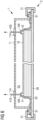
- Figure 1 is a cross-section through an embodiment of the inventive moulding apparatus 1, and shows a reusable bag 10 joined to a rigid housing 11. When not in use, as shown here, the reusable bag 10 hangs from the housing 11.
- the rigid housing 11 can have an essentially rectangular shape as shown in Figure 2 , since the beam of a wind turbine rotor blade is also essentially rectangular in shape. Along its lower edge, a rim 11R protrudes outwards. As explained above, the rigid housing 11 is constructed to retain its form under vacuum.
- the reusable bag 10 is joined to the rigid housing 11 by a form-fit upper perimeter seal 1US as shown in the enlarged region.
- a form-fit upper perimeter seal 1US As shown in the enlarged region.
- an upwardly protruding tongue 10FF is formed, and the underside of the housing rim 11R is formed with a complementary groove or recess 11FF.
- the flexible elastomer tongue 10FF can be manually pressed into the groove 11US in the underside of the housing rim 11R to complete the form fit.
- the form fit 1US extends all about the perimeter of the housing 11, so that the housing 11 and reusable bag 10 form a closed cavity S3, referred to herein as the lifting vacuum space S3.
- a lower perimeter seal arrangement 1LS extends along the perimeter of the bag 10 on its underside 102.
- the lower perimeter seal arrangement 1LS comprises a pair of essentially parallel beads B1, B2.
- the inner bead B1 (and optionally also the outer bead B2) is hollow and can have a tubular shape as shown here.
- One or more valves can be provided to connect a hollow bead to a pump so that pressurized air can inflate the hollow bead(s) B1, B2.
- An air extraction nozzle 10N extends from between the beads B1, B2 through the housing rim 11R and is accessible from outside the housing 11. The purpose of the nozzle will be explained below. Several such air extraction nozzles 10N can be provided, spaced at intervals along the housing rim 11R. The space between the beads B1, B2 is referred to herein as the perimeter seal vacuum space S1.
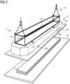
- Figure 2 shows a perspective view of the moulding apparatus 1 of Figure 1 , in which the essentially oblong or rectangular shape of the housing 11 is indicated.
- the moulding apparatus 1 is suspended above a lower mould 20 of a moulding assembly 2, in this case a flat table 20, supporting a laminate part 4.
- the diagram illustrates a stage prior to resin infusion and curing (the mould assembly 1 is being lowered into place to enclose the part 4), and also a stage after completion of curing (the mould assembly 1 has been released from the cured part 4 and is being lifted away from the table 20).
- the mould assembly 1 comprises a lifting structure 12 mounted to the rigid housing 11, for use in lifting the assembly 1 into place prior to an infusion procedure, and for removing the assembly 1 from the cured part.
- the spar cap of a long wind turbine rotor blade can have dimensions as described above.
- the housing 11 of the inventive moulding apparatus will exceed these dimensions and will therefore be correspondingly heavy.
- the lifting structure 12 is constructed so that the housing 11 does not deform when suspended from a lifting apparatus (not shown).
- the diagram also indicates several nozzles 10N extending from the perimeter seal vacuum space S1 of the reusable bag 10 (which is concealed from view by the housing 11) through the housing rim 11R.
- Figure 3 shows a view of the moulding apparatus 1 of Figures 1 and 2 from below, looking onto the reusable vacuum bag 10.
- the diagram shows the parallel beads B1, B2 of the inflatable seal arrangement 1LS extending about the perimeter of the sheet 10, and several air extraction nozzles 10N in the space between the beads B1, B2.
- the bag 10 is formed to comprise resin inlet features 10R which run the length of the laminate part 4 to distribute resin during the infusion procedure.
- the resin inlet features 10R are shaped to fit about resin inlet and outlet ports, and suitable seals can be attached about these ports to ensure that resin does not leak from within the infusion vacuum space.
- Figures 4 - 7 show exemplary stages of the inventive method
- Figure 8 shows the sequence of steps 80 - 88 in this exemplary embodiment of the method.
- step 80 the moulding apparatus 1 is suspended over a laminate beam 4 arranged on a moulding surface 20 or table.
- the diagram shows a widthwise cross-section through the moulding apparatus 1 and spar cap 4. While the housing 11 is suspended above the table 20, technicians secure the reusable vacuum bag 10 to the laminate part 4.
- a resin feed line 410 is attached to the laminate part 4 by a suitable resin inlet consumable 41.
- a resin extraction line 420 is attached to the laminate part 4 by a suitable resin outlet consumable 42.
- the resin lines 410, 420 can pass through suitable seals at appropriate locations in the enclosing structure 11. These connections can be made through the access openings 11A of the housing 11, which are then sealed in an air-tight fashion.
- step 81 the moulding apparatus 1 has been lowered onto the table 20 and has been released from the lifting apparatus.
- Clamps 21 are put into place about the moulding apparatus 1, to clamp the housing rim 11R and table 20.
- a pump is actuated to pump air into the inflatable bead(s) B1, B2 to a suitable pressure as explained above.
- stage 83 using a first vacuum pump, air is extracted through the nozzles 10N from the perimeter seal vacuum space S1 to create a first vacuum, which acts to press the perimeter of the elastomer sheet 10 onto the table 20, forming a tight seal.
- the clamps can be left in place so that, in a subsequent step, a favourably large underpressure can be achieved the infusion vacuum space S2.
- step 84 using a second vacuum pump, air is extracted through one or more nozzles - provided for example in the support surface - from the infusion vacuum space S2.
- the resulting vacuum in the infusion vacuum space S2 causes the reusable bag 10 to be pulled tightly against the laminate part 4 on all sides, and also against the table 20, as illustrated in Figure 6 , which shows a lengthwise cross-section through the moulding apparatus 1 and spar cap 4.
- stage 85 resin transfer is performed to infuse resin throughout the layers of the laminate part 4.
- resin infusion if for any reason there is a loss of vacuum in the infusion vacuum space S2, this can be remedied by the inventive moulding apparatus 1: a loss of vacuum in the infusion vacuum space S2 will connect the infusion vacuum space S2 and the perimeter seal vacuum space S1. Therefore, by actuating the first vacuum extraction means, the vacuum in the infusion vacuum space S2 can be re-established and the resin infusion stage need not be interrupted.
- step 86 the resin-infused part is allowed to cure. Curing can be assisted by heating elements incorporated in the table 20, and may also be assisted by heating elements incorporated in the reusable bag 10.
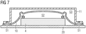
- the moulding apparatus 1 is removed in step 87 as illustrated in Figure 7 . This is done by venting air into the infusion vacuum space S2 to a moderate overpressure, thereby pushing the reusable bag 10 away from the laminate part 4.
- the perimeter seal vacuum space S1 is also vented to allow the space between the beads B1, B2 to fill with air.
- the moulding apparatus 1 is then raised from the table to allow the reusable bag 10 to lift from the edges of the cured part 4.
- a final stage 88 using a third vacuum pump, air is extracted from the lifting vacuum space S3. This creates a moderate underpressure between the reusable bag 10 and the housing 11, with the result that the reusable bag 10 is pulled outward and away from the cured part 4.
- the moulding apparatus 1 can then be lifted to a storage location until required again, as indicated in Figure 1 .
- Figure 9 shows a further realization of the elastomer sheet 10 of the inventive moulding apparatus 1.
- the sheet 10 is shown in place over a laminate part, as it may appear at some stage during the inventive method.
- the moulding apparatus 1 comprises a flow-front sensing assembly 13, with two line sensors S1, S2 attached to or embedded in the elastomer sheet 10.
- the line sensors S1, S2 detect a resin flow front (an exemplary resin flow direction is indicted by the arrow), and the progress of the flow front can be observed on a monitor 130.
- the moulding apparatus 1 also comprises a heating assembly 14, with a thin copper wire W embedded in the body of the elastomer sheet 10 and a means 140 of applying a voltage across the ends of the wire.
- This heating assembly 14 can be used in addition to a heating circuit provided in the support surface 20. After resin infusion is complete, an electric current can flow through the wire W, which becomes hot and facilitates a more even curing of the laminate part.
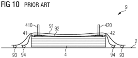
- Figure 10 shows a cross-section through a prior art moulding apparatus 9, in which a laminate part 4 is arranged on a lower mould surface 20 or table.
- two single-use bags 91, 92 are required, and these must be bonded to the lower mould surface 20, for example using butyl rubber tape.
- a first butyl tape 94 is manually applied to the table 20.
- a single-use inner bag 91 is then placed over a laminate part 4 and its perimeter is pressed onto the first butyl tape 94. This inner seal 94 is then tested for air-tightness.
- a second butyl tape 93 is then manually applied to the table 20 about the perimeter of the single-use inner bag 91.
- a larger single-use outer bag 92 is placed over the inner bag 91, and its perimeter is pressed onto the outer butyl tape 93. This outer seal 93 is then tested for air-tightness.
- a resin inlet branch 41 extends from the exterior through the bags 91, 92 to the laminate part 4 and is attached to the laminate part by an inlet consumable 410.
- a resin outlet branch 42 extends from the laminate part 4 through the bags 91, 92 to the exterior and is attached to the laminate part by an outlet consumable 420. After establishing a first vacuum between the inner bag 91 and the laminate part 4, and a second vacuum between the inner bag 91 and the outer bag 92, resin is infused through the inlet branch 41. The infused part 4 is then cured.
- the table 20 may incorporate heating elements (not shown) to facilitate curing.
- the single-use bags 91, 92 and the butyl seals 93, 94 are removed and discarded.
- the prior art approach is expensive, since the material cost of butyl tape and single-use bags for each casting cycle can be significant, particularly when many casting cycles are to be performed.
- it is time-consuming to apply the butyl seals 93, 94 and to perform the highly important tests for air-tightness, and these tasks require experienced personnel.
- a leak arising during the infusion process cannot be remedied and a partially infused laminate beam 4 may need to be discarded.
- the moulding apparatus can also be used to consolidate a preform element and hardening of this preform element.
Landscapes
- Chemical & Material Sciences (AREA)
- Engineering & Computer Science (AREA)
- Composite Materials (AREA)
- Mechanical Engineering (AREA)
- Casting Or Compression Moulding Of Plastics Or The Like (AREA)
Priority Applications (5)
| Application Number | Priority Date | Filing Date | Title |
|---|---|---|---|
| EP23168032.3A EP4446100A1 (de) | 2023-04-14 | 2023-04-14 | Formvorrichtung |
| PCT/EP2024/057895 WO2024213381A2 (en) | 2023-04-14 | 2024-03-25 | Moulding apparatus |
| CN202480025688.0A CN121100055A (zh) | 2023-04-14 | 2024-03-25 | 模制设备 |
| EP24715485.9A EP4669519A2 (de) | 2023-04-14 | 2024-03-25 | Formvorrichtung |
| TW113113777A TWI915790B (zh) | 2023-04-14 | 2024-04-12 | 成型設備、成型總成及鑄造層壓零件的方法 |
Applications Claiming Priority (1)
| Application Number | Priority Date | Filing Date | Title |
|---|---|---|---|
| EP23168032.3A EP4446100A1 (de) | 2023-04-14 | 2023-04-14 | Formvorrichtung |
Publications (1)
| Publication Number | Publication Date |
|---|---|
| EP4446100A1 true EP4446100A1 (de) | 2024-10-16 |
Family
ID=86051821
Family Applications (2)
| Application Number | Title | Priority Date | Filing Date |
|---|---|---|---|
| EP23168032.3A Withdrawn EP4446100A1 (de) | 2023-04-14 | 2023-04-14 | Formvorrichtung |
| EP24715485.9A Pending EP4669519A2 (de) | 2023-04-14 | 2024-03-25 | Formvorrichtung |
Family Applications After (1)
| Application Number | Title | Priority Date | Filing Date |
|---|---|---|---|
| EP24715485.9A Pending EP4669519A2 (de) | 2023-04-14 | 2024-03-25 | Formvorrichtung |
Country Status (3)
| Country | Link |
|---|---|
| EP (2) | EP4446100A1 (de) |
| CN (1) | CN121100055A (de) |
| WO (1) | WO2024213381A2 (de) |
Citations (3)
| Publication number | Priority date | Publication date | Assignee | Title |
|---|---|---|---|---|
| US20080211130A1 (en) * | 2007-02-23 | 2008-09-04 | Rydin Richard W | Method of making a natural rubber vacuum bag by spray processes, natural rubber vacuum bag made using spray process, and method for using natural rubber bag made using spray process |
| US20110146906A1 (en) * | 2009-12-18 | 2011-06-23 | The Boeing Company | Double Vacuum Cure Processing of Composite Parts |
| US20220332060A1 (en) * | 2021-04-14 | 2022-10-20 | The Boeing Company | Apparatus and method for processing a composite structure |
-
2023
- 2023-04-14 EP EP23168032.3A patent/EP4446100A1/de not_active Withdrawn
-
2024
- 2024-03-25 WO PCT/EP2024/057895 patent/WO2024213381A2/en not_active Ceased
- 2024-03-25 CN CN202480025688.0A patent/CN121100055A/zh active Pending
- 2024-03-25 EP EP24715485.9A patent/EP4669519A2/de active Pending
Patent Citations (3)
| Publication number | Priority date | Publication date | Assignee | Title |
|---|---|---|---|---|
| US20080211130A1 (en) * | 2007-02-23 | 2008-09-04 | Rydin Richard W | Method of making a natural rubber vacuum bag by spray processes, natural rubber vacuum bag made using spray process, and method for using natural rubber bag made using spray process |
| US20110146906A1 (en) * | 2009-12-18 | 2011-06-23 | The Boeing Company | Double Vacuum Cure Processing of Composite Parts |
| US20220332060A1 (en) * | 2021-04-14 | 2022-10-20 | The Boeing Company | Apparatus and method for processing a composite structure |
Also Published As
| Publication number | Publication date |
|---|---|
| WO2024213381A3 (en) | 2024-11-21 |
| CN121100055A (zh) | 2025-12-09 |
| TW202448598A (zh) | 2024-12-16 |
| EP4669519A2 (de) | 2025-12-31 |
| WO2024213381A2 (en) | 2024-10-17 |
Similar Documents
| Publication | Publication Date | Title |
|---|---|---|
| CN108943768B (zh) | 将物体柔性真空地固定到复杂表面 | |
| EP2457718B1 (de) | Verfahren zum blasenfreien Verdichten von Haftbundverbindungen | |
| EP2512786B1 (de) | Hochtemperatur-verbundwerkzeug | |
| EP2671709A1 (de) | Unbelüftetes Blasensystem zur Härtung von Verbundteilen | |
| US11927172B2 (en) | Method of forming a wind turbine blade | |
| JP6181190B2 (ja) | 複合材外板と複合材スティフナとをオートクレーブ内で共硬化するための方法及び装置 | |
| US11971009B2 (en) | Manufacturing a wind turbine blade shell part | |
| US10507622B2 (en) | System and method for curing polymer matrix composite parts in manufacturing and repairing processes | |
| EP4446100A1 (de) | Formvorrichtung | |
| DK2838711T3 (en) | A method of making a composite part and an apparatus for making a composite part | |
| US8641952B2 (en) | Fiber-reinforced component fabrication with mold cores | |
| US5836062A (en) | Apparatus for assembling a helicopter main rotor blade subassembly | |
| EP2952315A1 (de) | Verfahren zur Herstellung einer ein- oder mehrzelligen Verbundwerkstoffstruktur | |
| TWI915790B (zh) | 成型設備、成型總成及鑄造層壓零件的方法 | |
| CN111791517B (zh) | 中空囊状件修复方法 | |
| EP1019243A1 (de) | Gerät und verfahren zum zusammenstellen eines hubschrauber-hauptrotorblatts | |
| CN112109342A (zh) | 风电叶片模具及叶片的制造方法 | |
| EP2888097B1 (de) | Verfahren zur herstellung von verbundstrukturen und verschleissteilanordnung dafür | |
| EP4458563A1 (de) | Infusionsanordnung | |
| EP4556192A1 (de) | Verfahren und vorrichtung zum formen von verbundwerkstoff | |
| TW202423652A (zh) | 用於製造風力渦輪機轉子葉片的預製元件或預鑄元件之模具裝置以及用於製造這種預製元件或預鑄元件之方法 | |
| BR112021018337B1 (pt) | Fabricação de uma parte de carcaça de lâmina de turbina eólica |
Legal Events
| Date | Code | Title | Description |
|---|---|---|---|
| PUAI | Public reference made under article 153(3) epc to a published international application that has entered the european phase |
Free format text: ORIGINAL CODE: 0009012 |
|
| STAA | Information on the status of an ep patent application or granted ep patent |
Free format text: STATUS: THE APPLICATION HAS BEEN PUBLISHED |
|
| AK | Designated contracting states |
Kind code of ref document: A1 Designated state(s): AL AT BE BG CH CY CZ DE DK EE ES FI FR GB GR HR HU IE IS IT LI LT LU LV MC ME MK MT NL NO PL PT RO RS SE SI SK SM TR |
|
| STAA | Information on the status of an ep patent application or granted ep patent |
Free format text: STATUS: THE APPLICATION IS DEEMED TO BE WITHDRAWN |
|
| 18D | Application deemed to be withdrawn |
Effective date: 20250417 |