EP4446204A1 - Zone arrière latérale d'un véhicule automobile comprenant un dispositif de guidage d'air et véhicule automobile - Google Patents
Zone arrière latérale d'un véhicule automobile comprenant un dispositif de guidage d'air et véhicule automobile Download PDFInfo
- Publication number
- EP4446204A1 EP4446204A1 EP24000027.3A EP24000027A EP4446204A1 EP 4446204 A1 EP4446204 A1 EP 4446204A1 EP 24000027 A EP24000027 A EP 24000027A EP 4446204 A1 EP4446204 A1 EP 4446204A1
- Authority
- EP
- European Patent Office
- Prior art keywords
- guide
- air
- motor vehicle
- rear area
- air guiding
- Prior art date
- Legal status (The legal status is an assumption and is not a legal conclusion. Google has not performed a legal analysis and makes no representation as to the accuracy of the status listed.)
- Pending
Links
Images




Classifications
-
- B—PERFORMING OPERATIONS; TRANSPORTING
- B62—LAND VEHICLES FOR TRAVELLING OTHERWISE THAN ON RAILS
- B62D—MOTOR VEHICLES; TRAILERS
- B62D35/00—Vehicle bodies characterised by streamlining
- B62D35/008—Side spoilers
-
- B—PERFORMING OPERATIONS; TRANSPORTING
- B62—LAND VEHICLES FOR TRAVELLING OTHERWISE THAN ON RAILS
- B62D—MOTOR VEHICLES; TRAILERS
- B62D35/00—Vehicle bodies characterised by streamlining
- B62D35/007—Rear spoilers
-
- B—PERFORMING OPERATIONS; TRANSPORTING
- B62—LAND VEHICLES FOR TRAVELLING OTHERWISE THAN ON RAILS
- B62D—MOTOR VEHICLES; TRAILERS
- B62D37/00—Stabilising vehicle bodies without controlling suspension arrangements
- B62D37/02—Stabilising vehicle bodies without controlling suspension arrangements by aerodynamic means
Definitions
- the invention relates to a lateral rear area of a motor vehicle with an air guiding device.
- the invention also relates to a motor vehicle.
- Air guiding devices that are assigned to a side area of a motor vehicle and serve to guide the air flow there are also known as sideblades.
- DE 10 2019 207 906 A1 discloses a motor vehicle with a sideblade which is arranged above a rear wheel behind a window of a rear vehicle door.
- the invention relates to a side rear area of a motor vehicle with an air guiding device that serves to guide the flow in the side rear area behind a rear wheel house of the motor vehicle.
- the invention is based on the object of creating a side rear area with an air guiding device that enables a particularly advantageous flow guidance behind the rear wheel house of the motor vehicle.
- This object is achieved by a lateral rear region of a motor vehicle according to claim 1 and by a motor vehicle according to claim 11.
- the lateral rear area of the motor vehicle according to the invention has a rear body part which extends at least behind a rear wheel house of the motor vehicle.
- the lateral rear area of the motor vehicle according to the invention also has an air guiding device, wherein an air guiding element of the air guiding device can be displaced relative to the rear body part between a rest position retracted into the lateral rear area and an operating position extended from the lateral rear area in such a way that in the retracted rest position of the air guiding element a flow guiding surface of the air guiding element is covered by the rear body part, and that in the extended operating position of the air guiding element the flow guiding surface of the air guiding element is displaced relative to the retracted rest position on the one hand to the rear as seen in the longitudinal direction of the motor vehicle and on the other hand to the outside as seen in the transverse direction of the motor vehicle.
- the flow guide surface of the air guide element runs flush with an outer surface of the rear body part that is directly adjacent to the flow guide surface at the front.
- This is particularly preferred for advantageous flow guidance in the extended operating position.
- the flush transition between the flow guide surface of the air guide element and the outer surface of the rear body part that is directly adjacent to the flow guide surface of the extended air guide element at the front allows a particularly advantageous flow around the flow guide surface in the extended operating position of the air guiding device.
- the air guiding device has a guide and drive unit which guides and drives the air guide element during displacement relative to the rear body part.
- the guide and drive unit has at least one fixed guide rail and at least one sliding block which can be displaced relative to the fixed guide rail, wherein the air guide element engages with at least one guide pin in a guide groove of the respective guide rail and in at least one guide groove of the respective sliding block.
- the guide and drive unit also has a drive which displaces the respective sliding block relative to the respective guide rail and, via the respective sliding block, displaces the air guide element relative to the rear body part.
- the air guide element can be displaced particularly advantageously between the retracted rest position and the extended operating position via the guide and drive unit.
- the interaction of the at least one fixed guide rail, the at least one sliding block and the at least one guide bolt allows for easy displacement of the air guide element and thus of the flow guide surface both in the longitudinal direction and in the transverse direction of the motor vehicle when moving it between the retracted rest position and the extended operating position. There is no risk of the air guide element jamming during displacement.
- the guide groove of the respective guide rail has a first guide section for the displacement of the at least one guide pin and thus of the air guide element in the longitudinal direction or mainly in the longitudinal direction and at least one second guide section for the displacement of the at least one guide pin and thus of the air guide element in the transverse direction or mainly in the transverse direction, wherein the at least one guide groove of the at least one sliding block is curved and runs obliquely to the guide sections of the respective guide rail.
- the guide sections of the guide groove of the respective guide rail and the respective guide groove of the respective sliding block allow the displacement of the air guide element in the longitudinal direction and transverse direction of the motor vehicle in a particularly advantageous manner.
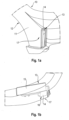
- Fig. 1a to 3b show a section of a lateral rear area 10 of a motor vehicle according to the invention.
- a rear body part 11 is shown from the lateral rear area 10, which extends in the lateral rear area 10 of the motor vehicle at least behind a rear wheel house 12 of the motor vehicle.
- Such a lateral rear area 10 is formed on both sides of the motor vehicle.
- the side rear area 10 has an air guiding device 13.
- the air guiding device 13 has an air guiding element 14 and a guide and drive unit 15.
- the air guiding element 14 can be moved relative to the rear body part 11 by means of the guide and drive unit 15 between a rest position retracted into the side rear area 10 (see Fig. 1a, 1b ) and an operating position extended from the same (see Fig. 3a, 3b ) can be shifted, whereby Fig. 2a, 2b an intermediate position of the air guide element 14 between the retracted rest position of the Fig. 1a, 1b and the extended operating position of the Fig. 3a, 3b show.
- the guide and drive unit 15 is completely concealed by the rear body part 11 and is mounted in or on the side rear area 10 such that the guide and drive unit 15 is fixed relative to the rear body part 11.
- the air guide element 14 can be moved relative to the guide and drive unit 15 and relative to the rear body part 11.
- the air guide element 14 has a flow guide surface 16.
- the flow guide surface 16 of the same In the retracted rest position ( Fig. 1a, 1b ) of the air guide element 14, the flow guide surface 16 of the same is retracted into the lateral rear area 10 and covered by the rear body part 11.
- the extended operating position ( Fig. 3a, 3b ) of the air guide element 14 In the extended operating position ( Fig. 3a, 3b ) of the air guide element 14, the flow guide surface 16 of the same is extended out of the lateral rear area 10 and is not covered by the rear body part 11, wherein the flow guide surface 16 of the air guide element 14 in the extended operating position is displaced backwards in the longitudinal direction of the motor vehicle on the one hand and outwards in the transverse direction of the motor vehicle on the other hand compared to the retracted rest position.
- the Fig. 1a, 1b In the retracted rest position ( Fig. 1a, 1b ) of the air guide element 14, the flow guide surface 16 of the same is
- Fig. 7a and 7b show the air guide element 14 of the air guiding device 13 in two different states, namely in Fig. 7a in the retracted rest position and in Fig. 7b in the extended operating position, whereby Fig. 7b again shows the flush transition between the flow guide surface 16 of the air guide element 14 extended into the operating position and the outer surface 17 of the rear body part 11 immediately adjacent to it.
- Fig. 7a and 7b show the air guide element 14 of the air guiding device 13 in two different states, namely in Fig. 7a in the retracted rest position and in Fig. 7b in the extended operating position, whereby Fig. 7b again shows the flush transition between the flow guide surface 16 of the air guide element 14 extended into the operating position and the outer surface 17 of the rear body part 11 immediately adjacent to it.
- Fig. 7a and 7b show the air guide element 14 of the air guiding device 13 in two different states, namely in Fig. 7a in the retracted rest position and in Fig. 7b in the extended operating
- an air flow LS is also shown in the area of the rear body part 11, namely in Fig. 7a an air flow LS with the air guide element 14 in the retracted rest position and in Fig. 7b with the air guide element 14 moved to the extended operating position.
- the flow guide surface 16 of the air guide element 14 is completely retracted into the lateral rear area 10 and is covered on the outside by the outer surface 17 of the rear body part 11.
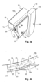
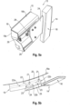
- FIG. 4a to 6b show further details of the air guiding device 13 of the lateral rear area 10 according to the invention, wherein in Fig. 4a to 6b the air guiding device 13 is shown in a single representation, namely in Fig. 4a, 4b in the retracted rest position, in Fig. 6a, 6b in the extended operating position and in Fig. 5a, 5b in an intermediate position between the retracted rest position and the extended operating position.
- the guide and drive unit 15 of the air guiding device 13, which serves to move the air guiding element 14 between the retracted rest position and the extended operating position, has a housing 18 consisting of a first housing part 18a and a second housing part 18b.
- a housing 18 consisting of a first housing part 18a and a second housing part 18b.
- Both housing parts 18a, 18b are shown.
- the second housing part 18b is not shown.
- At least one fixed guide rail 19 of the guide and drive unit 15 is accommodated in the housing 18.
- two such guide rails 19 are arranged in the housing 18, namely an upper fixed guide rail 19 and a lower fixed guide rail 19.
- the upper fixed guide rail 19 is visible.
- a sliding block 20 that can be moved relative to the respective fixed guide rail 19 interacts with the respective fixed guide rail 19.
- the air guide element 14 is guided by at least one guide pin 21 on a respective guide rail 19 and on a respective sliding block 20.
- two upper guide bolts 21 of the air guide element 14 cooperate with the upper fixed guide rail 19 and the upper sliding block 20.
- the lower fixed guide rail 19 and the lower sliding block 20 (in Fig. 4b , 5b , 6b not visible) preferably a single lower guide pin 21 of the air guide element 14 cooperates.
- the guide pins 21 engage in a guide groove 22 of the respective guide rail 19 and in a respective guide groove 23 of the respective sliding block 20.
- the respective sliding block 20 can be displaced relative to the respective guide rail 19 via a drive 28 of the guide and drive unit 15 and the air guide element 14 can be displaced relative to the rear body part 11 via the respective sliding block 20.
- the respective sliding block 20 is first displaced translationally along the respective guide rail 19, wherein the guide pin(s) 21 is or are displaced in a first guide section 22a of the respective guide groove 22 of the respective guide rail 19.
- the air guide element 14 assumes the intermediate position of the Fig. 5a, 5b a.
- the guide pin(s) 21, which are also guided in the at least one guide groove 23 of the sliding block 20 is/are pressed via the respective sliding block 20, namely the at least one guide groove 23 thereof, into second guide sections 22b of the guide groove 22 of the respective guide rail 19, specifically outwards in the transverse direction of the motor vehicle.
- This is brought about by the curved contour of the at least one guide groove 23 of the respective sliding block 20, which is curved and runs obliquely to the guide sections 22a, 22b of the guide groove 22 of the respective guide rail 19.
- the guide bolts 21 of the air guide element 14 are initially displaced along the first guide sections 22a of the guide grooves 22 of the guide rails 19 in the longitudinal direction or mainly in the longitudinal direction of the motor vehicle until this is no longer possible.
- the air guide element 14 then assumes the intermediate position of the Fig. 5b and is displaced backwards in the longitudinal direction of the vehicle.
- the first guide sections 22a of the guide grooves 22 of the guide rails 19 extend in the longitudinal direction or mainly in the longitudinal direction of the motor vehicle.
- the guide bolts 21 are then moved outwards in the transverse direction of the motor vehicle along the guide grooves 23 of the sliding blocks 20 and along the second guide sections 22b of the guide grooves 22 of the guide rails 19 extending in the transverse direction of the vehicle or mainly in the transverse direction of the vehicle.
- the air guide element 14 is then moved into the operating position of the Fig. 6b
- the second guide sections 22b run perpendicular to the first guide sections 22a.
- the air guiding device 13 or the air guiding element 14 has a tongue 24, on which projections 25 engage.
- the tongue 24 extends from the air guiding element 14 forwards in the longitudinal direction of the vehicle, can be moved together with the air guiding element 14 and is always covered by the rear body part 11.
- the tongue 24 is, so to speak, a component of the air guiding element 14, but does not provide the flow guiding surface 16 of the air guiding element 14.
- the projections 25 extend from the tongue 24 in the transverse direction of the vehicle.
- the guide pins 21 are formed or arranged on the projections 25.
- the projections 25 and guide pins 21 are also, so to speak, a component of the air guiding element 14.
- the projections 25 extend from a side of the tongue 24 facing away from the flow guide surface 16 with sections through slots 26 in the housing part 18b into the housing 18.
- the guide bolts 21 are formed or arranged on the sections of these projections 25 positioned in the housing 18.
- a superimposed double guide is provided through the interaction of the respective guide rail 19 with the respective sliding block 20.
- a displacement takes place in the longitudinal direction or mainly in the longitudinal direction, then a displacement takes place in the transverse direction or mainly in the transverse direction.
Landscapes
- Engineering & Computer Science (AREA)
- Chemical & Material Sciences (AREA)
- Combustion & Propulsion (AREA)
- Transportation (AREA)
- Mechanical Engineering (AREA)
- Physics & Mathematics (AREA)
- Fluid Mechanics (AREA)
- Air-Conditioning For Vehicles (AREA)
Applications Claiming Priority (3)
| Application Number | Priority Date | Filing Date | Title |
|---|---|---|---|
| DE102023109191.3A DE102023109191B4 (de) | 2023-04-12 | 2023-04-12 | Seitlicher Heckbereich eines Kraftfahrzeugs mit einer Luftleitvorrichtung und Kraftfahrzeug |
| DE102023109208.1A DE102023109208B4 (de) | 2023-04-12 | 2023-04-12 | Seitlicher Heckbereich eines Kraftfahrzeugs mit einer Luftleitvorrichtung und Kraftfahrzeug |
| DE102023117958.6A DE102023117958A1 (de) | 2023-07-07 | 2023-07-07 | Seitlicher Heckbereich eines Kraftfahrzeugs mit einer Luftleitvorrichtung und Kraftfahrzeug |
Publications (1)
| Publication Number | Publication Date |
|---|---|
| EP4446204A1 true EP4446204A1 (fr) | 2024-10-16 |
Family
ID=90363586
Family Applications (1)
| Application Number | Title | Priority Date | Filing Date |
|---|---|---|---|
| EP24000027.3A Pending EP4446204A1 (fr) | 2023-04-12 | 2024-03-05 | Zone arrière latérale d'un véhicule automobile comprenant un dispositif de guidage d'air et véhicule automobile |
Country Status (2)
| Country | Link |
|---|---|
| US (1) | US20240343319A1 (fr) |
| EP (1) | EP4446204A1 (fr) |
Families Citing this family (1)
| Publication number | Priority date | Publication date | Assignee | Title |
|---|---|---|---|---|
| DE102023109535B3 (de) * | 2023-04-17 | 2024-03-28 | Dr. Ing. H.C. F. Porsche Aktiengesellschaft | Luftleitelement und Kraftfahrzeug mit einem Luftleitelement |
Citations (9)
| Publication number | Priority date | Publication date | Assignee | Title |
|---|---|---|---|---|
| DE102007003601A1 (de) | 2006-01-18 | 2007-07-26 | Küster Automotive Control Systems GmbH | Vorrichtung zum Verstellen eines bewegbaren Karosserieteils |
| DE202011005504U1 (de) | 2011-04-21 | 2011-10-26 | Hs Genion Gmbh | Fahrzeug mit Luftleitvorrichtung |
| FR3001192A1 (fr) | 2013-01-21 | 2014-07-25 | Peugeot Citroen Automobiles Sa | Dispositif pour commander le deploiement et la retraction d'un ou plusieurs deflecteurs destines a etre montes de facon mobile sous le bouclier avant d'un vehicule automobile. |
| US20160318560A1 (en) * | 2015-04-28 | 2016-11-03 | Toyota Jidosha Kabushiki Kaisha | Vehicle rear portion structure |
| DE102018123487A1 (de) | 2018-09-24 | 2020-03-26 | Röchling Automotive SE & Co. KG | Aktiv verlagerbarer Radspoiler mit Überlastschutz durch Knickelement |
| DE102019114113A1 (de) | 2019-05-27 | 2020-12-03 | Bayerische Motoren Werke Aktiengesellschaft | Kraftfahrzeug |
| DE102019207906A1 (de) | 2019-05-29 | 2020-12-03 | Audi Ag | Kraftfahrzeug mit einem Sideblade |
| DE102020103140A1 (de) * | 2020-02-07 | 2021-08-12 | Dr. Ing. H.C. F. Porsche Aktiengesellschaft | Luftleitvorrichtung für ein Kraftfahrzeug und Verfahren für eine Luftleitvorrichtung |
| DE102021118408B3 (de) * | 2021-07-16 | 2022-08-04 | Dr. Ing. H.C. F. Porsche Aktiengesellschaft | Luftleitvorrichtung für ein Kraftfahrzeug |
-
2024
- 2024-03-05 EP EP24000027.3A patent/EP4446204A1/fr active Pending
- 2024-03-28 US US18/619,384 patent/US20240343319A1/en active Pending
Patent Citations (9)
| Publication number | Priority date | Publication date | Assignee | Title |
|---|---|---|---|---|
| DE102007003601A1 (de) | 2006-01-18 | 2007-07-26 | Küster Automotive Control Systems GmbH | Vorrichtung zum Verstellen eines bewegbaren Karosserieteils |
| DE202011005504U1 (de) | 2011-04-21 | 2011-10-26 | Hs Genion Gmbh | Fahrzeug mit Luftleitvorrichtung |
| FR3001192A1 (fr) | 2013-01-21 | 2014-07-25 | Peugeot Citroen Automobiles Sa | Dispositif pour commander le deploiement et la retraction d'un ou plusieurs deflecteurs destines a etre montes de facon mobile sous le bouclier avant d'un vehicule automobile. |
| US20160318560A1 (en) * | 2015-04-28 | 2016-11-03 | Toyota Jidosha Kabushiki Kaisha | Vehicle rear portion structure |
| DE102018123487A1 (de) | 2018-09-24 | 2020-03-26 | Röchling Automotive SE & Co. KG | Aktiv verlagerbarer Radspoiler mit Überlastschutz durch Knickelement |
| DE102019114113A1 (de) | 2019-05-27 | 2020-12-03 | Bayerische Motoren Werke Aktiengesellschaft | Kraftfahrzeug |
| DE102019207906A1 (de) | 2019-05-29 | 2020-12-03 | Audi Ag | Kraftfahrzeug mit einem Sideblade |
| DE102020103140A1 (de) * | 2020-02-07 | 2021-08-12 | Dr. Ing. H.C. F. Porsche Aktiengesellschaft | Luftleitvorrichtung für ein Kraftfahrzeug und Verfahren für eine Luftleitvorrichtung |
| DE102021118408B3 (de) * | 2021-07-16 | 2022-08-04 | Dr. Ing. H.C. F. Porsche Aktiengesellschaft | Luftleitvorrichtung für ein Kraftfahrzeug |
Also Published As
| Publication number | Publication date |
|---|---|
| US20240343319A1 (en) | 2024-10-17 |
Similar Documents
| Publication | Publication Date | Title |
|---|---|---|
| EP1275541B1 (fr) | Module, spécialement module coulissant pour véhicule | |
| EP0638452A1 (fr) | Système de fermeture ou d'ouverture au moins partielle d'un couvercle pour toit basculant-coulissant | |
| DE102004020335A1 (de) | Rollosystem für ein Fahrzeugdach | |
| DE102023109191B4 (de) | Seitlicher Heckbereich eines Kraftfahrzeugs mit einer Luftleitvorrichtung und Kraftfahrzeug | |
| DE102015119405A1 (de) | Schiebedachmodul und Verfahren zur Herstellung des Schiebedachmoduls | |
| EP4446204A1 (fr) | Zone arrière latérale d'un véhicule automobile comprenant un dispositif de guidage d'air et véhicule automobile | |
| EP1577136A2 (fr) | Toit coulissant arrangement | |
| EP3138711A2 (fr) | Systeme de toit de vehicule automobile | |
| DE4326291A1 (de) | Fahrzeugdach | |
| DE102023109208B4 (de) | Seitlicher Heckbereich eines Kraftfahrzeugs mit einer Luftleitvorrichtung und Kraftfahrzeug | |
| DE102023117958A1 (de) | Seitlicher Heckbereich eines Kraftfahrzeugs mit einer Luftleitvorrichtung und Kraftfahrzeug | |
| DE102007001286B4 (de) | Öffenbares Fahrzeugdach mit Antriebsschlitten für ein Dachelement | |
| DE60009784T2 (de) | Konstruktion eines öffnungsfähigen Fahrzeugdaches | |
| EP1721770B1 (fr) | Glissière pour un système de toit coulissant de véhicule automobile | |
| DE102020112528A1 (de) | Kraftfahrzeug mit einer Karosserie | |
| DE19635145C1 (de) | Fahrzeugdach | |
| WO2000021766A1 (fr) | Leve-vitre commande par cable pour vehicules | |
| DE60205200T2 (de) | Kompakter Seilfensterheber | |
| DE10361874A1 (de) | Vorrichtung zum Verstellen eines Kraftfahrzeugteils | |
| DE10123423B4 (de) | Antrieb für ein Schließelement eines Fahrzeugdaches | |
| DE10203882B4 (de) | Mehrteiliges Schiebedach | |
| DE102019110082A1 (de) | Windabweiser für eine Scheibenwischanlage eines Kraftwagens | |
| EP1380718B1 (fr) | Dispositif pour l'actionnement automatique d'une porte coulissante de véhicule | |
| DE20111621U1 (de) | Endplombe für ein Kabel sowie Baugruppe bestehend aus einer Endplombe, einem Schlitten und einem Kabel | |
| EP0064135A1 (fr) | Lève-vitre |
Legal Events
| Date | Code | Title | Description |
|---|---|---|---|
| PUAI | Public reference made under article 153(3) epc to a published international application that has entered the european phase |
Free format text: ORIGINAL CODE: 0009012 |
|
| STAA | Information on the status of an ep patent application or granted ep patent |
Free format text: STATUS: THE APPLICATION HAS BEEN PUBLISHED |
|
| AK | Designated contracting states |
Kind code of ref document: A1 Designated state(s): AL AT BE BG CH CY CZ DE DK EE ES FI FR GB GR HR HU IE IS IT LI LT LU LV MC ME MK MT NL NO PL PT RO RS SE SI SK SM TR |
|
| STAA | Information on the status of an ep patent application or granted ep patent |
Free format text: STATUS: REQUEST FOR EXAMINATION WAS MADE |
|
| 17P | Request for examination filed |
Effective date: 20250422 |