EP4446206A1 - Dispositif de stationnement de bicyclette pour un véhicule - Google Patents
Dispositif de stationnement de bicyclette pour un véhicule Download PDFInfo
- Publication number
- EP4446206A1 EP4446206A1 EP23305545.8A EP23305545A EP4446206A1 EP 4446206 A1 EP4446206 A1 EP 4446206A1 EP 23305545 A EP23305545 A EP 23305545A EP 4446206 A1 EP4446206 A1 EP 4446206A1
- Authority
- EP
- European Patent Office
- Prior art keywords
- bicycle parking
- wheel
- column
- bicycle
- axis
- Prior art date
- Legal status (The legal status is an assumption and is not a legal conclusion. Google has not performed a legal analysis and makes no representation as to the accuracy of the status listed.)
- Granted
Links
Images
Classifications
-
- B—PERFORMING OPERATIONS; TRANSPORTING
- B62—LAND VEHICLES FOR TRAVELLING OTHERWISE THAN ON RAILS
- B62H—CYCLE STANDS; SUPPORTS OR HOLDERS FOR PARKING OR STORING CYCLES; APPLIANCES PREVENTING OR INDICATING UNAUTHORIZED USE OR THEFT OF CYCLES; LOCKS INTEGRAL WITH CYCLES; DEVICES FOR LEARNING TO RIDE CYCLES
- B62H3/00—Separate supports or holders for parking or storing cycles
- B62H3/12—Hanging-up devices
-
- B—PERFORMING OPERATIONS; TRANSPORTING
- B60—VEHICLES IN GENERAL
- B60P—VEHICLES ADAPTED FOR LOAD TRANSPORTATION OR TO TRANSPORT, TO CARRY, OR TO COMPRISE SPECIAL LOADS OR OBJECTS
- B60P3/00—Vehicles adapted to transport, to carry or to comprise special loads or objects
- B60P3/06—Vehicles adapted to transport, to carry or to comprise special loads or objects for carrying vehicles
- B60P3/07—Vehicles adapted to transport, to carry or to comprise special loads or objects for carrying vehicles for carrying road vehicles
- B60P3/073—Vehicle retainers
- B60P3/075—Vehicle retainers for wheels, hubs, or axle shafts
-
- B—PERFORMING OPERATIONS; TRANSPORTING
- B61—RAILWAYS
- B61D—BODY DETAILS OR KINDS OF RAILWAY VEHICLES
- B61D37/00—Other furniture or furnishings
-
- B—PERFORMING OPERATIONS; TRANSPORTING
- B61—RAILWAYS
- B61D—BODY DETAILS OR KINDS OF RAILWAY VEHICLES
- B61D45/00—Means or devices for securing or supporting the cargo, including protection against shocks
- B61D45/001—Devices for fixing to walls or floors
-
- B—PERFORMING OPERATIONS; TRANSPORTING
- B62—LAND VEHICLES FOR TRAVELLING OTHERWISE THAN ON RAILS
- B62H—CYCLE STANDS; SUPPORTS OR HOLDERS FOR PARKING OR STORING CYCLES; APPLIANCES PREVENTING OR INDICATING UNAUTHORIZED USE OR THEFT OF CYCLES; LOCKS INTEGRAL WITH CYCLES; DEVICES FOR LEARNING TO RIDE CYCLES
- B62H3/00—Separate supports or holders for parking or storing cycles
- B62H3/08—Separate supports or holders for parking or storing cycles involving recesses or channelled rails for embracing the bottom part of a wheel
-
- E—FIXED CONSTRUCTIONS
- E04—BUILDING
- E04H—BUILDINGS OR LIKE STRUCTURES FOR PARTICULAR PURPOSES; SWIMMING OR SPLASH BATHS OR POOLS; MASTS; FENCING; TENTS OR CANOPIES, IN GENERAL
- E04H6/00—Buildings for parking cars, rolling-stock, aircraft, vessels or like vehicles, e.g. garages
- E04H6/005—Garages for vehicles on two wheels
Definitions
- the present invention relates to a bicycle parking device comprising : a column extending along a first axis between a first end and a second end ; and a wheel fixing element, able to slide along the column between a first and a second axial positions, respectively close to the first end and close to the second end.
- Such a bicycle parking device is disclosed in document WO2018104800 .
- the known bicycle parking devices may be adapted only to a limited range of size/height/weight of bicycles.
- the bicycles are usually pressed against each other for space gain. Therefore, it may be difficult for a particular user to remove his/her own bicycle among others, or to access a free place surrounded with occupied ones.
- the present invention aims to solve the above-mentioned problems.
- the invention relates to a bicycle parking device of the aforementioned type, also comprising : a supporting element, the column being able to rotate relative to said supporting element around the first axis, between a first and a second angular positions ; and a wheel receptacle, integral with the first end of the column and extending from said first end along a second axis, perpendicular to the first axis.
- the bicycle parking device is configured so as to receive a bicycle with a frame and a first and a second wheels, the first wheel being fixed to the wheel fixing element in the second axial position, the second wheel being in contact with the wheel receptacle, so that the bicycle is able to rotate relative to the supporting element, together with the column.
- the bicycle parking device may include one or more of the following features, considered alone or in any technically possible combination:
- the present invention also relates to a bicycle parking assembly comprising : a bicycle parking device as disclosed above ; and a translation device coupled with the supporting element of said bicycle parking device, so that the supporting element is able to translate relative to the translation device, along a third axis substantially perpendicular to the first axis.
- the bicycle parking assembly comprises a plurality of bicycle parking devices as disclosed above ; wherein the supporting elements of the plurality of bicycle parking devices are coupled with the translation device so that the supporting elements of the plurality of bicycle parking devices are able to translate relative to the translation device along the third axis.
- the present invention also relates to a vehicle comprising a floor and a bicycle parking device as disclosed above, the supporting element of the bicycle parking device being assembled to the floor.
- the vehicle may include one or more of the following features, considered alone or in any technically possible combination:
- the present invention also relates to a vehicle comprising a floor and a bicycle parking assembly as disclosed above, wherein the translation device comprises a lower element fixed to the floor a lower end of the supporting element of each of the plurality of bicycle parking devices being coupled with the lower element, so that the supporting elements of the plurality of bicycle parking devices are able to translate relative to the floor along the third axis.
- the vehicle comprises an inner wall
- the translation device comprises an upper element fixed to the inner wall, an upper end of the supporting element of each of the plurality of bicycle parking devices being coupled with the upper element.
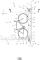
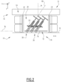
- Figures 1 and 2 show a vehicle 10 according to an embodiment of the invention.
- the vehicle 10 is a land vehicle, more preferably a railway vehicle such as a train.
- the vehicle 10 comprises a floor 12, and at least one inner wall 14, for example a lateral wall.
- the floor 12 and the lateral wall 14 define an inner compartment 16 together with a roof (not shown).
- X represents a moving direction, considered horizontal, of the vehicle 10 ; and Z represents the vertical direction.
- the floor 12 and the inner wall 14 shown on Figures 1 and 2 extend respectively along a (X, Y) plane and along a (X, Z) plane.
- the inner compartment 16 comprises : a circulation area 18, extending along X ; and a bicycle parking zone 20.
- the bicycle parking zone 20 is located along Y between the circulation area 18 and the inner wall 14 ; and delimited along X between a first 22 and a second 23 panels.
- the bicycle parking zone 20 is configured for accommodating one or more bicycles 24, shown on Figures 1 and 2 .
- a typical bicycle 24 comprises : a frame 25 ; and a first 26 and a second 27 wheels able to rotate relative to the frame 25.
- the first 26 and the second 27 wheels substantially extend along a same plane and have rotation axes 28, 29 substantially parallel to each other.
- the bicycle parking zone 20 comprises at least one bicycle parking device 30.
- the bicycle parking device 30 comprises : a supporting element 32 ; a column 34 ; a wheel fixing element 36 ; a wheel receptacle 38 ; and a first 40 and a second 42 actuation devices.
- the supporting element 32 extends along a vertical main axis 44.
- a lower end 46 of the supporting element 32 is assembled to the floor 12. In an embodiment (not shown), the lower end 46 is fixedly assembled to the floor 12.
- the supporting element 32 is a vertical rod and an upper end 48 of said supporting element 32 is assembled to a cantilever 50 fixed to the inner wall 14.
- the cantilever 50 is a rail extending along X between the first 22 and second 23 panels.
- the upper end 48 of the supporting element 32 is assembled to the roof of the inner compartment 16. In another embodiment (not shown), the upper end 48 of the supporting element 32 is a free end.
- the column 34 extends along the vertical main axis 44, between a lower end 52 and an upper end 54.
- the column 34 is able to rotate around the main axis 44 relative to the supporting element 32.
- the column 34 is ring-shaped around the supporting element 32.
- the column 34 is able to rotate between a first and a second angular positions, shown respectively on Figure 1 and on Figure 2 .
- the first and second angular positions form a tilt angle ⁇ comprised between 10° and 35°. More preferably, the tilt angle ⁇ is comprised between 20° and 35°. In the embodiment of Figures 1 and 2 , the tilt angle ⁇ is close to 35°.
- the first actuation device 40 allows a user to rotate the column 34 between the first and the second angular positions.
- the first actuation device 40 comprises a gripping element, attached to the column.
- the first actuation device 40 comprises a braking element (not shown) between the column 34 and the supporting element 32, so that the rotation needs an initial force above a selected threshold ; and/or so that the rotation between the first and second angular positions is decomposed in several steps of a same angular pitch.
- the wheel fixing element 36 comprises a first body 56 and a first locking device 58.
- the first body 56 is able to slide along the column between a lower (not shown) and an upper positions. In the upper position, shown on Figures 1 and 2 , the first body 56 is closer to the upper end 54 of the column. In the lower position, the first body 56 is closer to the lower end 52.
- a suitable sliding mechanism for the first body 56 is disclosed in document WO2018104800 , previously cited.
- the first locking device 58 is able to lock the first 26 or second 27 wheel of a bicycle in contact with the first body 56.
- a suitable locking device is disclosed in document WO2018104800 , previously cited.
- the second actuation device 42 allows a user to move the wheel fixing element 36 between the lower and upper positions.
- the second actuation device 42 is a lever situated at the bottom of the column 34, as disclosed in document WO2018104800 , previously cited.
- the wheel receptacle 38 is integral with the lower end 52 of the column and extends from said first end along a receptacle axis 60, perpendicular to the main axis 44.
- the receptacle axis 60 is horizontal.
- the receptacle axis 60 extends along Y in the first angular position of the column 34.
- the receptacle axis 60 is inclined relative to Y in the second angular position of the column 34.
- the tilt angle ⁇ corresponds to the angle between the receptacle axis 60 in the first angular position and the receptacle axis 60 in the second angular position.
- the wheel receptacle 38 comprises a second body 62, able to accommodate a wheel 27, 26 of the bicycle 24 when the other wheel 26, 27 is assembled to the wheel fixing element 36 and when said wheel fixing element is in the upper position.
- the second body 62 has a substantially constant section along the receptacle axis 60.
- the second body 62 has a U-shaped or V-shaped section so as to form a groove, able to receive the wheel 27, 26.
- a free end of the wheel receptacle 38, opposed to the column 34, is open.
- the wheel receptacle 38 also comprises a second locking device 64 for locking the wheel in contact with the second body 62.
- the bicycle parking zone 20 comprises a plurality of bicycle parking devices 30 according to the description above, the main axis 44 of each of said bicycle parking devices 30 extending vertically.
- the bicycle parking devices 30 are substantially identical.
- the main axes 44 of the plurality of bicycle parking devices 30 are aligned.
- the bicycle parking zone 20 comprises three bicycle parking devices 30, the main axes of said bicycle parking devices being aligned along X.
- the lower end of the supporting element of each of the plurality of bicycle parking devices 30 is fixedly assembled to the floor 12.
- the bicycle parking zone 20 comprises a bicycle parking assembly 70.
- the bicycle parking assembly 70 comprises : at least one bicycle parking device 30 according to the description above ; and a translation device 72.
- the translation device 72 is fixed to the floor 12 and/or inner wall 14 and/or roof (not shown) of the inner compartment 16.
- the translation device 72 comprises at least a lower element 74 fixed relative to the floor 12 and extending along a translation axis 76 parallel to X.
- the lower element 74 extends between the first 22 and second 23 panels.
- the lower element 74 is for example a lower rail carved into the floor 12.
- the lower end 46 of the supporting element is slidably coupled to the lower element 74, so that the supporting element 32 is able to translate along the translation axis 76 relative to the translation device.
- the translation device 72 also comprises an upper element 78 such as an upper rail, fixed to the cantilever 50 and extending along X between the first 22 and second 23 panels.
- the upper end 48 of the supporting element is slidably coupled to the upper element 78.
- the bicycle parking zone 20 comprises a plurality of bicycle parking devices 30 according to the description above.
- the supporting element 32 of each of said bicycle parking devices 30 is slidably coupled to the translation device 72, so that each supporting element 32 is able to translate along the translation axis 76 relative to the translation device 72.
- a user enters the inner compartment 16 together with a bicycle 24 and moves on the circulation area 18 so as to face the bicycle parking zone 20.
- the user places the bicycle 24, or at least the first wheel 26, aligned along Y with an unoccupied bicycle parking device 30 ; so that the first wheel 26 faces the column 34 and so that the rotation axis 28of at least the first wheel is parallel to X.
- the user actuates the first actuation device 40 so as to place the column 34 in the first angular position ; and/or the user actuates the second actuation device 42 so as to place the wheel fixing element 36 in the lower position.
- the user places the first wheel 26 on the wheel receptacle 38, in lateral contact with the first body 56 of the wheel fixing element 36 ; and actuates the first locking device 58, so as to fix the first wheel 26 to the first body 56.
- the user actuates the second actuation device 42 so as to place the wheel fixing element 36 in the upper position.
- the second actuation device 42 is actuated by pushing the bicycle against the wheel fixing element.
- the vertical movement of the wheel fixing element 36 drives the second wheel 27 into the wheel receptacle 38, in contact with the second body 62.
- the user then actuates the second locking device 64 so as to fix the second wheel 27 to the second body 62.
- the bicycle parking device 30 and the bicycle 24, assembled to each other, are then in the configuration shown on Figure 1 .
- a part of the bicycle 24 protrudes from the bicycle parking zone 20 on the circulation area 18, which may hamper the circulation of the passengers in the inner compartment 16.
- the user actuates the first actuation device 40, so as to place the column 34 in the second angular position of Figure 2 .
- the receptacle axis 60 is thus inclined relative to Y and the bicycle 24 is entirely located in the bicycle parking zone 20, between the first 22 and second 23 panels.
- the circulation area 18 is not obstructed by the bicycle.
- the reverse method is carried out by the user in order to remove the bicycle 24 from the bicycle parking device 30.
- the bicycle parking zone 20 comprises several bicycle parking devices 30, some of them being already occupied by a bicycle, the user may place each column 34 in the first angular position. A better access is thus provided to an unoccupied bicycle parking device 30.
- the bicycle parking zone 20 comprises a bicycle parking assembly 70 with a translation device 72
- the user may translate the bicycle parking devices 30 along the translation axis 76 for a better access to an unoccupied bicycle parking device.
- each of the bicycle parking devices 30 is easily accessible to a user, even if the adjacent bicycle parking devices are already occupied with a bicycle ; and when the columns 34 are in the second angular positions, the bicycles do not obstruct the circulation in the inner compartment 16.
- the bicycle parking devices 30 is adapted to a wide range of size/height/weight of bicycles 24.
- the bicycle parking devices 30 is adapted to electric bikes.
Landscapes
- Engineering & Computer Science (AREA)
- Mechanical Engineering (AREA)
- Architecture (AREA)
- Transportation (AREA)
- Health & Medical Sciences (AREA)
- Public Health (AREA)
- Civil Engineering (AREA)
- Structural Engineering (AREA)
- Handcart (AREA)
- Automatic Cycles, And Cycles In General (AREA)
Priority Applications (2)
| Application Number | Priority Date | Filing Date | Title |
|---|---|---|---|
| ES23305545T ES3049775T3 (en) | 2023-04-12 | 2023-04-12 | Bicycle parking device for a vehicle |
| EP23305545.8A EP4446206B1 (fr) | 2023-04-12 | 2023-04-12 | Dispositif de stationnement de bicyclette pour un véhicule |
Applications Claiming Priority (1)
| Application Number | Priority Date | Filing Date | Title |
|---|---|---|---|
| EP23305545.8A EP4446206B1 (fr) | 2023-04-12 | 2023-04-12 | Dispositif de stationnement de bicyclette pour un véhicule |
Publications (2)
| Publication Number | Publication Date |
|---|---|
| EP4446206A1 true EP4446206A1 (fr) | 2024-10-16 |
| EP4446206B1 EP4446206B1 (fr) | 2025-09-10 |
Family
ID=86329407
Family Applications (1)
| Application Number | Title | Priority Date | Filing Date |
|---|---|---|---|
| EP23305545.8A Active EP4446206B1 (fr) | 2023-04-12 | 2023-04-12 | Dispositif de stationnement de bicyclette pour un véhicule |
Country Status (2)
| Country | Link |
|---|---|
| EP (1) | EP4446206B1 (fr) |
| ES (1) | ES3049775T3 (fr) |
Citations (4)
| Publication number | Priority date | Publication date | Assignee | Title |
|---|---|---|---|---|
| EP1609708A1 (fr) * | 2004-06-23 | 2005-12-28 | Marco Tschümperlin | Dispositif pour garer des bicyclettes |
| WO2018104800A1 (fr) | 2016-12-09 | 2018-06-14 | Uab Parkis | Dispositif de stationnement de bicyclette |
| CN108505785A (zh) * | 2018-05-25 | 2018-09-07 | 武汉纺织大学 | 一种双塔立式自行车自动停放装置 |
| CN208731115U (zh) * | 2018-08-22 | 2019-04-12 | 河北农业大学 | 一种回转式自行车竖直存放装置 |
-
2023
- 2023-04-12 EP EP23305545.8A patent/EP4446206B1/fr active Active
- 2023-04-12 ES ES23305545T patent/ES3049775T3/es active Active
Patent Citations (4)
| Publication number | Priority date | Publication date | Assignee | Title |
|---|---|---|---|---|
| EP1609708A1 (fr) * | 2004-06-23 | 2005-12-28 | Marco Tschümperlin | Dispositif pour garer des bicyclettes |
| WO2018104800A1 (fr) | 2016-12-09 | 2018-06-14 | Uab Parkis | Dispositif de stationnement de bicyclette |
| CN108505785A (zh) * | 2018-05-25 | 2018-09-07 | 武汉纺织大学 | 一种双塔立式自行车自动停放装置 |
| CN208731115U (zh) * | 2018-08-22 | 2019-04-12 | 河北农业大学 | 一种回转式自行车竖直存放装置 |
Also Published As
| Publication number | Publication date |
|---|---|
| ES3049775T3 (en) | 2025-12-18 |
| EP4446206B1 (fr) | 2025-09-10 |
Similar Documents
| Publication | Publication Date | Title |
|---|---|---|
| JP4012728B2 (ja) | 降下可能な荷物室を備えた飛行機の客室用荷物棚 | |
| US8382057B2 (en) | Low profile seat track system | |
| US5626361A (en) | Roll-over protection arrangement for a motor vehicle | |
| EP1967411B1 (fr) | Agencement de plancher de chargement | |
| JP7345294B2 (ja) | 客室内における座席配列の変更構造 | |
| US20150367754A1 (en) | Seat track assembly having load absorption features | |
| US20170050502A1 (en) | Roof system for an automotive vehicle | |
| CN101437707A (zh) | 用于机动车辆的箱体的配置构造和包括这种箱体的配置构造的机动车辆 | |
| KR100362128B1 (ko) | 휘일체어를고정하기위한장치 | |
| EP4446206A1 (fr) | Dispositif de stationnement de bicyclette pour un véhicule | |
| DE102011012904A1 (de) | Anordnung zum Halten eines Fahrrades | |
| EP1221001B1 (fr) | Mecanisme cinematique du type a cremaillere, en particulier pour pont elevateur pour vehicules | |
| EP1918183B1 (fr) | Dispositif pour faciliter le garage de motocyclettes ou similaires, en particulier pour le garage dans des espaces restreints | |
| US11541942B2 (en) | Vehicle bottom structure | |
| EP4286315B1 (fr) | Cabine d'ascenseur comportant un boîtier électrique mobile | |
| JP2006513927A (ja) | 自動車両との前面衝突の際に人を保護する装置 | |
| US6309014B1 (en) | Roof arrangement | |
| CN103448516B (zh) | 具有固定的翻车防护杆的机动车辆 | |
| CN114590179A (zh) | 汽车座椅 | |
| KR20210089580A (ko) | 가변 경사 트랙에서 승객을 수송하기 위한 충격 흡수식 차량 및 차량을 포함하는 설비 | |
| KR102325531B1 (ko) | 분리방지형 추락방지도어를 포함하는 주차구조물의 진출입 도어 어셈블리 | |
| CN218579381U (zh) | 电梯上梁组件 | |
| JP2009241628A (ja) | 二輪車駐輪装置 | |
| KR20200037211A (ko) | 차량용 시트 구조 | |
| US20250341109A1 (en) | Parking facility and method for operating same |
Legal Events
| Date | Code | Title | Description |
|---|---|---|---|
| PUAI | Public reference made under article 153(3) epc to a published international application that has entered the european phase |
Free format text: ORIGINAL CODE: 0009012 |
|
| STAA | Information on the status of an ep patent application or granted ep patent |
Free format text: STATUS: THE APPLICATION HAS BEEN PUBLISHED |
|
| STAA | Information on the status of an ep patent application or granted ep patent |
Free format text: STATUS: REQUEST FOR EXAMINATION WAS MADE |
|
| AK | Designated contracting states |
Kind code of ref document: A1 Designated state(s): AL AT BE BG CH CY CZ DE DK EE ES FI FR GB GR HR HU IE IS IT LI LT LU LV MC ME MK MT NL NO PL PT RO RS SE SI SK SM TR |
|
| 17P | Request for examination filed |
Effective date: 20241010 |
|
| RBV | Designated contracting states (corrected) |
Designated state(s): AL AT BE BG CH CY CZ DE DK EE ES FI FR GB GR HR HU IE IS IT LI LT LU LV MC ME MK MT NL NO PL PT RO RS SE SI SK SM TR |
|
| GRAP | Despatch of communication of intention to grant a patent |
Free format text: ORIGINAL CODE: EPIDOSNIGR1 |
|
| STAA | Information on the status of an ep patent application or granted ep patent |
Free format text: STATUS: GRANT OF PATENT IS INTENDED |
|
| RIC1 | Information provided on ipc code assigned before grant |
Ipc: E04H 6/00 20060101ALI20250403BHEP Ipc: B61D 45/00 20060101ALI20250403BHEP Ipc: B61D 37/00 20060101ALI20250403BHEP Ipc: B60P 3/075 20060101ALI20250403BHEP Ipc: B62H 3/08 20060101ALI20250403BHEP Ipc: B62H 3/12 20060101AFI20250403BHEP |
|
| INTG | Intention to grant announced |
Effective date: 20250415 |
|
| GRAS | Grant fee paid |
Free format text: ORIGINAL CODE: EPIDOSNIGR3 |
|
| GRAA | (expected) grant |
Free format text: ORIGINAL CODE: 0009210 |
|
| STAA | Information on the status of an ep patent application or granted ep patent |
Free format text: STATUS: THE PATENT HAS BEEN GRANTED |
|
| AK | Designated contracting states |
Kind code of ref document: B1 Designated state(s): AL AT BE BG CH CY CZ DE DK EE ES FI FR GB GR HR HU IE IS IT LI LT LU LV MC ME MK MT NL NO PL PT RO RS SE SI SK SM TR |
|
| REG | Reference to a national code |
Ref country code: GB Ref legal event code: FG4D |
|
| REG | Reference to a national code |
Ref country code: CH Ref legal event code: EP |
|
| REG | Reference to a national code |
Ref country code: DE Ref legal event code: R096 Ref document number: 602023006586 Country of ref document: DE |
|
| REG | Reference to a national code |
Ref country code: IE Ref legal event code: FG4D |
|
| P01 | Opt-out of the competence of the unified patent court (upc) registered |
Free format text: CASE NUMBER: UPC_APP_0011073_4446206/2025 Effective date: 20251027 |
|
| REG | Reference to a national code |
Ref country code: ES Ref legal event code: FG2A Ref document number: 3049775 Country of ref document: ES Kind code of ref document: T3 Effective date: 20251218 |
|
| PG25 | Lapsed in a contracting state [announced via postgrant information from national office to epo] |
Ref country code: NO Free format text: LAPSE BECAUSE OF FAILURE TO SUBMIT A TRANSLATION OF THE DESCRIPTION OR TO PAY THE FEE WITHIN THE PRESCRIBED TIME-LIMIT Effective date: 20251210 |
|
| REG | Reference to a national code |
Ref country code: LT Ref legal event code: MG9D |
|
| PG25 | Lapsed in a contracting state [announced via postgrant information from national office to epo] |
Ref country code: FI Free format text: LAPSE BECAUSE OF FAILURE TO SUBMIT A TRANSLATION OF THE DESCRIPTION OR TO PAY THE FEE WITHIN THE PRESCRIBED TIME-LIMIT Effective date: 20250910 |
|
| REG | Reference to a national code |
Ref country code: NL Ref legal event code: MP Effective date: 20250910 |
|
| PG25 | Lapsed in a contracting state [announced via postgrant information from national office to epo] |
Ref country code: HR Free format text: LAPSE BECAUSE OF FAILURE TO SUBMIT A TRANSLATION OF THE DESCRIPTION OR TO PAY THE FEE WITHIN THE PRESCRIBED TIME-LIMIT Effective date: 20250910 |
|
| PG25 | Lapsed in a contracting state [announced via postgrant information from national office to epo] |
Ref country code: GR Free format text: LAPSE BECAUSE OF FAILURE TO SUBMIT A TRANSLATION OF THE DESCRIPTION OR TO PAY THE FEE WITHIN THE PRESCRIBED TIME-LIMIT Effective date: 20251211 |
|
| PG25 | Lapsed in a contracting state [announced via postgrant information from national office to epo] |
Ref country code: SE Free format text: LAPSE BECAUSE OF FAILURE TO SUBMIT A TRANSLATION OF THE DESCRIPTION OR TO PAY THE FEE WITHIN THE PRESCRIBED TIME-LIMIT Effective date: 20250910 |
|
| PG25 | Lapsed in a contracting state [announced via postgrant information from national office to epo] |
Ref country code: LV Free format text: LAPSE BECAUSE OF FAILURE TO SUBMIT A TRANSLATION OF THE DESCRIPTION OR TO PAY THE FEE WITHIN THE PRESCRIBED TIME-LIMIT Effective date: 20250910 |
|
| PG25 | Lapsed in a contracting state [announced via postgrant information from national office to epo] |
Ref country code: BG Free format text: LAPSE BECAUSE OF FAILURE TO SUBMIT A TRANSLATION OF THE DESCRIPTION OR TO PAY THE FEE WITHIN THE PRESCRIBED TIME-LIMIT Effective date: 20250910 Ref country code: PL Free format text: LAPSE BECAUSE OF FAILURE TO SUBMIT A TRANSLATION OF THE DESCRIPTION OR TO PAY THE FEE WITHIN THE PRESCRIBED TIME-LIMIT Effective date: 20250910 |
|
| PG25 | Lapsed in a contracting state [announced via postgrant information from national office to epo] |
Ref country code: RS Free format text: LAPSE BECAUSE OF FAILURE TO SUBMIT A TRANSLATION OF THE DESCRIPTION OR TO PAY THE FEE WITHIN THE PRESCRIBED TIME-LIMIT Effective date: 20251210 |
|
| REG | Reference to a national code |
Ref country code: AT Ref legal event code: MK05 Ref document number: 1835641 Country of ref document: AT Kind code of ref document: T Effective date: 20250910 |
|
| PG25 | Lapsed in a contracting state [announced via postgrant information from national office to epo] |
Ref country code: NL Free format text: LAPSE BECAUSE OF FAILURE TO SUBMIT A TRANSLATION OF THE DESCRIPTION OR TO PAY THE FEE WITHIN THE PRESCRIBED TIME-LIMIT Effective date: 20250910 |
|
| PG25 | Lapsed in a contracting state [announced via postgrant information from national office to epo] |
Ref country code: SM Free format text: LAPSE BECAUSE OF FAILURE TO SUBMIT A TRANSLATION OF THE DESCRIPTION OR TO PAY THE FEE WITHIN THE PRESCRIBED TIME-LIMIT Effective date: 20250910 |
|
| PG25 | Lapsed in a contracting state [announced via postgrant information from national office to epo] |
Ref country code: AT Free format text: LAPSE BECAUSE OF FAILURE TO SUBMIT A TRANSLATION OF THE DESCRIPTION OR TO PAY THE FEE WITHIN THE PRESCRIBED TIME-LIMIT Effective date: 20250910 |
|
| PG25 | Lapsed in a contracting state [announced via postgrant information from national office to epo] |
Ref country code: IT Free format text: LAPSE BECAUSE OF FAILURE TO SUBMIT A TRANSLATION OF THE DESCRIPTION OR TO PAY THE FEE WITHIN THE PRESCRIBED TIME-LIMIT Effective date: 20250910 |
|
| PG25 | Lapsed in a contracting state [announced via postgrant information from national office to epo] |
Ref country code: IS Free format text: LAPSE BECAUSE OF FAILURE TO SUBMIT A TRANSLATION OF THE DESCRIPTION OR TO PAY THE FEE WITHIN THE PRESCRIBED TIME-LIMIT Effective date: 20260110 |
|
| PG25 | Lapsed in a contracting state [announced via postgrant information from national office to epo] |
Ref country code: CZ Free format text: LAPSE BECAUSE OF FAILURE TO SUBMIT A TRANSLATION OF THE DESCRIPTION OR TO PAY THE FEE WITHIN THE PRESCRIBED TIME-LIMIT Effective date: 20250910 Ref country code: PT Free format text: LAPSE BECAUSE OF FAILURE TO SUBMIT A TRANSLATION OF THE DESCRIPTION OR TO PAY THE FEE WITHIN THE PRESCRIBED TIME-LIMIT Effective date: 20260112 |
|
| PG25 | Lapsed in a contracting state [announced via postgrant information from national office to epo] |
Ref country code: SK Free format text: LAPSE BECAUSE OF FAILURE TO SUBMIT A TRANSLATION OF THE DESCRIPTION OR TO PAY THE FEE WITHIN THE PRESCRIBED TIME-LIMIT Effective date: 20250910 Ref country code: EE Free format text: LAPSE BECAUSE OF FAILURE TO SUBMIT A TRANSLATION OF THE DESCRIPTION OR TO PAY THE FEE WITHIN THE PRESCRIBED TIME-LIMIT Effective date: 20250910 |