EP4446237A1 - Arrêt de groupe auxiliaire de puissance autonome et temps de refroidissement automatique - Google Patents
Arrêt de groupe auxiliaire de puissance autonome et temps de refroidissement automatique Download PDFInfo
- Publication number
- EP4446237A1 EP4446237A1 EP24169822.4A EP24169822A EP4446237A1 EP 4446237 A1 EP4446237 A1 EP 4446237A1 EP 24169822 A EP24169822 A EP 24169822A EP 4446237 A1 EP4446237 A1 EP 4446237A1
- Authority
- EP
- European Patent Office
- Prior art keywords
- apu
- power unit
- auxiliary power
- aircraft
- cooldown
- Prior art date
- Legal status (The legal status is an assumption and is not a legal conclusion. Google has not performed a legal analysis and makes no representation as to the accuracy of the status listed.)
- Pending
Links
Images


Classifications
-
- B—PERFORMING OPERATIONS; TRANSPORTING
- B64—AIRCRAFT; AVIATION; COSMONAUTICS
- B64D—EQUIPMENT FOR FITTING IN OR TO AIRCRAFT; FLIGHT SUITS; PARACHUTES; ARRANGEMENT OR MOUNTING OF POWER PLANTS OR PROPULSION TRANSMISSIONS IN AIRCRAFT
- B64D31/00—Power plant control systems; Arrangement of power plant control systems in aircraft
- B64D31/02—Initiating means
- B64D31/06—Initiating means actuated automatically
-
- B—PERFORMING OPERATIONS; TRANSPORTING
- B64—AIRCRAFT; AVIATION; COSMONAUTICS
- B64D—EQUIPMENT FOR FITTING IN OR TO AIRCRAFT; FLIGHT SUITS; PARACHUTES; ARRANGEMENT OR MOUNTING OF POWER PLANTS OR PROPULSION TRANSMISSIONS IN AIRCRAFT
- B64D41/00—Power installations for auxiliary purposes
-
- F—MECHANICAL ENGINEERING; LIGHTING; HEATING; WEAPONS; BLASTING
- F01—MACHINES OR ENGINES IN GENERAL; ENGINE PLANTS IN GENERAL; STEAM ENGINES
- F01D—NON-POSITIVE DISPLACEMENT MACHINES OR ENGINES, e.g. STEAM TURBINES
- F01D21/00—Shutting-down of machines or engines, e.g. in emergency; Regulating, controlling, or safety means not otherwise provided for
-
- F—MECHANICAL ENGINEERING; LIGHTING; HEATING; WEAPONS; BLASTING
- F02—COMBUSTION ENGINES; HOT-GAS OR COMBUSTION-PRODUCT ENGINE PLANTS
- F02C—GAS-TURBINE PLANTS; AIR INTAKES FOR JET-PROPULSION PLANTS; CONTROLLING FUEL SUPPLY IN AIR-BREATHING JET-PROPULSION PLANTS
- F02C9/00—Controlling gas-turbine plants; Controlling fuel supply in air- breathing jet-propulsion plants
-
- F—MECHANICAL ENGINEERING; LIGHTING; HEATING; WEAPONS; BLASTING
- F05—INDEXING SCHEMES RELATING TO ENGINES OR PUMPS IN VARIOUS SUBCLASSES OF CLASSES F01-F04
- F05D—INDEXING SCHEME FOR ASPECTS RELATING TO NON-POSITIVE-DISPLACEMENT MACHINES OR ENGINES, GAS-TURBINES OR JET-PROPULSION PLANTS
- F05D2220/00—Application
- F05D2220/50—Application for auxiliary power units (APU's)
Definitions
- the technology relates to aircraft, and more particularly to an Auxiliary Power Unit (APU) control system and methods and systems for more efficiently operating and shutting down an APU.
- APU Auxiliary Power Unit
- an Auxiliary Power Unit refers to an onboard device that consists of a Gas Turbine Engine used in aircraft operation to provide pneumatic and/or shaft power to the aircraft systems.
- APU pneumatic power/compressed air supply from the APU's gas turbine is used by the aircraft environmental control system to pressurize the aircraft cabin and to feed the aircraft air conditioning systems.
- APU pneumatic power is also used to start the main engines.
- the APU's shaft power is typically converted to electrical power that is used to feed the aircraft systems in a situation where the main engine electrical generator or the aircraft batteries are not available.
- the APU utilizes aircraft fuel to operate and provide power. Therefore, the APU is, along with the main engine, an aircraft fuel consumer and carbon emission source. See for example US20210276725 , incorporated herein by reference. Improvements are therefore possible and desirable to decrease the amount of fuel the APU consumes.
- the APU used in an aircraft system is typically a constant speed, integral bleed, continuous cycle gas turbine engine.
- the gas turbine features include a compressor (usually centrifugal), a combustor and a turbine.
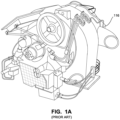
- the APU is often installed on board the aircraft within an APU compartment in the aircraft tail cone at the back of the aircraft (see FIG. 1B ) or in a nacelle.
- One example APU is rated at approximately six-hundred horsepower and utilizes a single-stage compressor impeller and a two-stage axial turbine mounted on a common rotor shaft.
- the APU principle of operation generally consists of the following: the APU start is initiated when commanded by the aircraft pilot, copilot or other flight crew in the cockpit (hereinafter, "pilot” refers to any or all such personnel). Often this involves turning the APU on and then momentarily depressing a "START" control to start the APU.
- aircraft systems will provide electrical or pneumatic power to accelerate the APU compressor to a point where fuel can be added to the combustor and ignited.
- the aircraft power that supports APU start is gradually removed until APU combustion is sustained by the mixture of APU compressor air and fuel.
- APU start is concluded once the APU reaches its 100% rated speed, which is typically indicated on the aircraft instrument panel. It typically takes a few minutes for the APU to come up to speed.
- APU start at the 100% rated speed, the APU enters into steady state operation where it is capable of providing electrical power and/or pneumatic power to the aircraft.
- the principle of APU operation consists of the following: the aircraft air inlet system provides air to the APU compressor. Pressurized air is conducted to the APU combustor. At this stage, fuel is added to the combustor and the mixture is auto-ignited and directed to the APU turbine. As the air expands, the turbine's rotation provides shaft power to the accessories linked to the APU shaft (typically an electrical generator). Pressurized air is bled from the APU compressor to feed pneumatic power to the aircraft systems.
- the APU is designed to provide electrical/pneumatic power according to the aircraft demand.
- the design includes different operating conditions, such as:
- the pilot may command a shutdown.
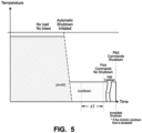
- a cooldown cycle is performed.
- the APU pneumatic load and the APU generator/electrical load are removed aiming to stabilize the APU at a lower temperature before completing the shutdown.
- This cooldown can reduce the risk of thermal shock which can damage the machine (e.g., providing a cooldown can extend the life of the turbine of the APU).
- the cooldown cycle lowers combustor and atomizer skin temperatures to prevent coking.
- the cooldown time magnitude/duration may vary from engine type-to-engine type, or even between engines of the same type, and will often depend on the aircraft installation. Often the cooldown period once the APU temperature has stabilized may be 2 or 3 minutes. The APU may be shut down at the end of this cooldown period.
- an immediate automatic APU shutdown may occur either on the ground or in flight, upon detecting any of the following conditions:
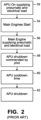
- APU control technology does not take into account APU power demand condition in order to start counting the cooldown time.
- the cooldown time is just initiated when the APU control unit receives the engine shutdown input (e.g. master switch) directly from the pilot or indirectly, depending on the aircraft systems architecture (see Fig.2 ).
- the engine shutdown input e.g. master switch
- the technology herein will hereinafter be described in conjunction with figures to depict the system and pilot interaction face to autonomous APU shutdown.
- the technology herein will have an automatic cooldown time start and an autonomous APU shutdown right after main engines start if the APU is not supplying any power to the aircraft, such as, pneumatic, electrical, etc.
- the autonomous APU shutdown will reduce the pilot workload in the cockpit, and as a convenience, after APU shutdown, the pilot can move the master switch 152 to the "stop" position.
- the autonomous APU shutdown and automatic cooldown time will reduce the APU operation time on ground, resulting in fuel burn reduction, cost saving and emissions reduction of many tons of CO2 per year.
- FIG. 3 illustrates working mechanisms of an embodiment of an aircraft including an APU 116 and an APU control system 150.
- the normal operation of main gas turbine jet engines 102, 104 produce air that is both compressed (high pressure) and heated (high temperature). While the aircraft is flying, the engines 102, 104 themselves provide a convenient source of pressurized hot air to for example maintain cabin temperature and pressure.
- such gas turbine engines 102, 104 use an initial stage air compressor to feed the engine with compressed air.
- Some of this compressed heated air from certain compressor stages of the operating gas turbine engines 102, 104 is bled from the engine and used for other purposes (e.g., cabin pressurization and temperature maintenance by an environmental control system or ECS under control of an environmental control unit processor 110) without adversely affecting engine operation and efficiency.
- other purposes e.g., cabin pressurization and temperature maintenance by an environmental control system or ECS under control of an environmental control unit processor 110
- Bleed air provided by the APU 116, the ground pneumatic source 118, the left engine(s) 102, the right engine(s) 104 is supplied for example via bleed airflow manifold and associated pressure regulators and temperature limiters to the ECS air conditioning units 108 of the aircraft.
- the main engines 102, 104 are typically not operating or are not operating at full capacity. Accordingly, compressed air is supplied from a different source.
- Such other bleed air sources for ground operation include the APU 116 and the ground pneumatic sources 118.
- the APU 116 is a constant speed, integral bleed, continuous cycle gas turbine engine as described above.
- Figure 1A shows a non-limiting example of an APU 116 - in this case a Pratt & Whitney APS2300 APU comprising an integral bleed, constant speed, continuous cycle gas turbine engine that incorporates a single-stage centrifugal compressor, a reverse flow annular combustor, and a two-stage axial turbine. See for example USP 7,204,090 , incorporated herein by reference. Other types of conventional APUs 116 can be used.
- the APU 116 includes a power section, a compressor and a gearbox.
- the APU 116 power section may be a gas turbine that rotates the APU's main shaft.
- a compressor mounted on the main shaft provides pneumatic power to the aircraft.
- the compressor typically has two actuated devices: inlet guide vanes which regulate airflow to the load compressor, and a surge control valve which allows the surge-free operation.
- a gearbox transfers power from the APU 116 main shaft to an oil-cooled electrical generator for generating electrical power. Mechanical power is also transferred inside the gearbox to engine accessories such as a fuel control unit, a cooling fan and a lubrication module.
- the APU control system 150 can operate the APU gearbox to selectively couple and decouple loads to/from the APU output shaft.
- the APU control system 105 can also open and close air valve 125c to selectively allow and prevent flow of pressurized air generated by the APU 116 to the aircraft pneumatic system such as the ECS 108.
- the APU 116 in one embodiment is generally operated as shown in Figure 2 .
- the APU start is initiated when commanded by the aircraft pilot (202) e.g., by turning the Master APU control 152 from “OFF” to "ON” and then momentarily to "START".
- aircraft systems provide electrical or pneumatic power to accelerate APU 116 compressor to a point where fuel can be supplied to the combustor and the fuel can be ignited.
- the aircraft power (motor or pneumatic driver) that supports APU start is gradually removed until APU combustion is sustained self-sufficiently by the mixture of APU compressor air and fuel.
- APU start is concluded once APU reaches its 100% rated speed (204).
- a cockpit display typically displays the status of the APU, i.e., that it is ON and what percentage of its rated speed it is operating at.
- APU 116 After APU 116 starts at the 100% rated speed of the APU, the APU begins operating in steady state operation where it is capable of providing electrical power and/or pneumatic power to the aircraft.
- An example principle of APU 116 operation in this stage consists of the following: the aircraft air inlet system provides air to the APU compressor. Pressurized air is conducted to the APU 116 combustor. At this stage, fuel is added to the combustor and the mixture is auto-ignited and directed to the APU turbine. As the air expands, the turbine's rotation provides shaft power to accessories linked to the APU 116 shaft (typically an electrical generator). Pressurized air is bled from the APU compressor to feed pneumatic power to the aircraft systems.
- the pilot may command the APU to shut down (block 58).
- the pilot may depress the STOP button 154.
- the APU control system 150 typically removes the loads from the APU and times an APU cooldown time as described above (see FIG. 2A ) before shutting down the APU.
- the pilot may depress the guarded "FUEL SHUTOFF" button 156 to immediately cut off the APU's fuel supply.
- the FADEC it is also known for the FADEC to monitor various parameters associated with APU operation and provide an immediate (or sometimes delayed by a certain amount of time) automatic shutoff.
- Example embodiments herein expand such autonomous operation by providing a conditioned autonomous APU shutdown based on an automatic cooldown time.
- Such autonomous automatic shutdown may be performed by a processor arrangement or computer arrangement such as the FADEC 150 comprising at least one processor executing software instructions stored in at least one non-transitory memory and using a real time clock (RTC) 160 to time intervals.
- a processor arrangement or computer arrangement such as the FADEC 150 comprising at least one processor executing software instructions stored in at least one non-transitory memory and using a real time clock (RTC) 160 to time intervals.
- RTC real time clock
- Other embodiments may provide a controller that is based on a hardware ASIC containing logic circuitry including a hardware timer and comparators, or a combination of hardware and software, as those skilled in the art will understand.
- Such autonomous automatic shutdown may interact with manual input provided by the pilot so the pilot may choose to keep the APU on, but will automatically detect whether there is a load on the APU and if there is none, operate the APU instead in a lower temperature cooldown mode until the pilot decides to turn off the APU, at which point the control system can immediately turn off the APU because it has already been operating at a stabilized cooldown temperature.
- the pilot will or may soon demand power again from APU and would like APU power to be available immediately without having to restart APU. It is difficult to list all reasons why a pilot might wish to keep the APU on and increase the fuel burn of the mission but example reasons include:
- the APU control unit 150 will not wait for pilot input to start the cooldown time, it will instead be automatically initiated. In parallel, the control unit 150 will also set autonomous APU shutdown. Then, after a measured cooldown time, the APU will shut down if the pilot does not take any action e.g., to override the shutdown. As shown in FIG. 4 , in example embodiments:
- the APU control unit 150 knows if/when the APU is on (block 202) and is providing power to the aircraft (decision block 204); if the APU is not applying power to the aircraft ("N" exit to decision block 204), the autonomous APU shutdown state is set, the control system 150 decouples the loads from the APU 116 so the APU can operate at a lower stabilized cooldown temperature, and the cooldown time counting is automatically initiated (block 206).
- the APU control unit 150 may initiate the automatic autonomous APU shutdown even though the pilot has not operated controls 152, 154 to order a shutdown.
- the pilot will eventually command an APU shutdown by operating controls 152, 154. At that time, the APU will be immediately shutdown (block 224) after the pilot command (block 214) if:
- the control system will still wait until the cooldown time has completed before shutting down the APU (block 216, 218).
- the pilot's shutdown command does not extend or reset the cooldown time period in example embodiments. Rather, the automatic countdown time which the example embodiment control system began counting at block 206 continues to be counted.
Landscapes
- Engineering & Computer Science (AREA)
- Aviation & Aerospace Engineering (AREA)
- Mechanical Engineering (AREA)
- General Engineering & Computer Science (AREA)
- Chemical & Material Sciences (AREA)
- Combustion & Propulsion (AREA)
- Control Of Eletrric Generators (AREA)
- Control Of Turbines (AREA)
Applications Claiming Priority (1)
| Application Number | Priority Date | Filing Date | Title |
|---|---|---|---|
| US202363459357P | 2023-04-14 | 2023-04-14 |
Publications (1)
| Publication Number | Publication Date |
|---|---|
| EP4446237A1 true EP4446237A1 (fr) | 2024-10-16 |
Family
ID=90730324
Family Applications (1)
| Application Number | Title | Priority Date | Filing Date |
|---|---|---|---|
| EP24169822.4A Pending EP4446237A1 (fr) | 2023-04-14 | 2024-04-12 | Arrêt de groupe auxiliaire de puissance autonome et temps de refroidissement automatique |
Country Status (3)
| Country | Link |
|---|---|
| US (1) | US20250382064A1 (fr) |
| EP (1) | EP4446237A1 (fr) |
| CN (1) | CN118877217A (fr) |
Citations (6)
| Publication number | Priority date | Publication date | Assignee | Title |
|---|---|---|---|---|
| US7204090B2 (en) | 2004-06-17 | 2007-04-17 | Pratt & Whitney Canada Corp. | Modulated current gas turbine engine starting system |
| US20110127372A1 (en) * | 2004-09-27 | 2011-06-02 | The Boeing Company | Automatic control systems for aircraft auxiliary power units, and associated methods |
| EP2554482A1 (fr) * | 2011-08-03 | 2013-02-06 | Hamilton Sundstrand Corporation | Cycle de refroidissement sélectif pour APU |
| US20180237153A1 (en) * | 2017-02-20 | 2018-08-23 | Pratt & Whitney Canada Corp. | System and method for controlling an auxiliary power unit inlet door |
| EP3680469A1 (fr) * | 2019-01-10 | 2020-07-15 | Honeywell International Inc. | Système et procédé de cycle de refroidissement adaptatif d'unité d'alimentation auxiliaire |
| US20210276725A1 (en) | 2020-03-05 | 2021-09-09 | Yaborã Indústria Aeronáutica S.A. | Systems and Methods for Defining APU Steady State Speed according to the Aircraft Operational Conditions |
Family Cites Families (1)
| Publication number | Priority date | Publication date | Assignee | Title |
|---|---|---|---|---|
| US11649763B1 (en) * | 2022-06-23 | 2023-05-16 | Raytheon Technologies Corporation | Rating control architecture and method for hybrid electric engine |
-
2024
- 2024-04-05 US US18/628,536 patent/US20250382064A1/en active Pending
- 2024-04-12 EP EP24169822.4A patent/EP4446237A1/fr active Pending
- 2024-04-15 CN CN202410449245.6A patent/CN118877217A/zh active Pending
Patent Citations (6)
| Publication number | Priority date | Publication date | Assignee | Title |
|---|---|---|---|---|
| US7204090B2 (en) | 2004-06-17 | 2007-04-17 | Pratt & Whitney Canada Corp. | Modulated current gas turbine engine starting system |
| US20110127372A1 (en) * | 2004-09-27 | 2011-06-02 | The Boeing Company | Automatic control systems for aircraft auxiliary power units, and associated methods |
| EP2554482A1 (fr) * | 2011-08-03 | 2013-02-06 | Hamilton Sundstrand Corporation | Cycle de refroidissement sélectif pour APU |
| US20180237153A1 (en) * | 2017-02-20 | 2018-08-23 | Pratt & Whitney Canada Corp. | System and method for controlling an auxiliary power unit inlet door |
| EP3680469A1 (fr) * | 2019-01-10 | 2020-07-15 | Honeywell International Inc. | Système et procédé de cycle de refroidissement adaptatif d'unité d'alimentation auxiliaire |
| US20210276725A1 (en) | 2020-03-05 | 2021-09-09 | Yaborã Indústria Aeronáutica S.A. | Systems and Methods for Defining APU Steady State Speed according to the Aircraft Operational Conditions |
Also Published As
| Publication number | Publication date |
|---|---|
| CN118877217A (zh) | 2024-11-01 |
| US20250382064A1 (en) | 2025-12-18 |
Similar Documents
| Publication | Publication Date | Title |
|---|---|---|
| US7802757B2 (en) | Method and system for taxiing an aircraft | |
| US5143329A (en) | Gas turbine engine powered aircraft environmental control system and boundary layer bleed | |
| EP0459816B1 (fr) | Système de contrôle de climatisation et d'élimination de la couche limite entraîné par une turbine à gaz pour avion | |
| EP2884075B1 (fr) | Système de moteur d'avion comprenant un moteur principal, un démarreur et une unité de puissance auxiliaire | |
| US12291344B2 (en) | Aircraft performance optimization based on engine performance monitoring | |
| JP2019023068A (ja) | 航空機用推進システム | |
| JP6608825B2 (ja) | ヘリコプタのターボシャフトエンジン、対応する制御デバイス、およびそのようなデバイスが設けられたヘリコプタの作動速度を自動的に制御するための方法。 | |
| US12110121B2 (en) | Systems and methods for defining APU steady state speed according to the aircraft operational conditions | |
| US11391203B2 (en) | Asymmetric propulsion system with heat recovery | |
| EP3835565B1 (fr) | Système et procédé de test de performance de moteur en vol | |
| EP3260376A1 (fr) | Fonctionnement d'une unité de puissance auxiliaire lors du fonctionnement d'un système de propulsion non nominal | |
| EP4421294B1 (fr) | Moteur à turbine à gaz hybride-électrique et procédé de fonctionnement | |
| CA3112003A1 (fr) | Systeme et methode de surveillance d`un moteur avant l`arret | |
| EP4446237A1 (fr) | Arrêt de groupe auxiliaire de puissance autonome et temps de refroidissement automatique | |
| KR20220078693A (ko) | 착륙 후 헬리콥터 로터의 신속정지 방법 | |
| US11698032B1 (en) | Systems and methods for controlling noise in aircraft powered by hybrid-electric gas turbine engines | |
| BR102024007112A2 (pt) | Desligamento autônomo de motor e tempo de resfriamento automático | |
| Hönle et al. | Engine quick start in case of emergency-A requirement for saving fuel by means of engine shutdown | |
| US12618335B2 (en) | In-flight hybrid electric engine shutdown | |
| US20240056007A1 (en) | Gas-turbine electrical start system | |
| Rodgers | Auxiliary power units for current and future aircraft | |
| Xiaogang | Flight Test Investigation to the Start Performance of Military Aircraft APU Considered with Airworthiness | |
| EP3960997A1 (fr) | Arrêt et redémarrage d'un moteur électrique-hybride en vol | |
| Xiaogang | Flight Test Investigation to the Start Performance of Military Aircraft APU | |
| Tudosie | Turboshaft-type APU For Aircraft As Controlled Object |
Legal Events
| Date | Code | Title | Description |
|---|---|---|---|
| PUAI | Public reference made under article 153(3) epc to a published international application that has entered the european phase |
Free format text: ORIGINAL CODE: 0009012 |
|
| STAA | Information on the status of an ep patent application or granted ep patent |
Free format text: STATUS: THE APPLICATION HAS BEEN PUBLISHED |
|
| AK | Designated contracting states |
Kind code of ref document: A1 Designated state(s): AL AT BE BG CH CY CZ DE DK EE ES FI FR GB GR HR HU IE IS IT LI LT LU LV MC ME MK MT NL NO PL PT RO RS SE SI SK SM TR |
|
| STAA | Information on the status of an ep patent application or granted ep patent |
Free format text: STATUS: REQUEST FOR EXAMINATION WAS MADE |
|
| 17P | Request for examination filed |
Effective date: 20250416 |
|
| P01 | Opt-out of the competence of the unified patent court (upc) registered |
Free format text: CASE NUMBER: APP_19336/2025 Effective date: 20250423 |
|
| GRAP | Despatch of communication of intention to grant a patent |
Free format text: ORIGINAL CODE: EPIDOSNIGR1 |
|
| STAA | Information on the status of an ep patent application or granted ep patent |
Free format text: STATUS: GRANT OF PATENT IS INTENDED |
|
| INTG | Intention to grant announced |
Effective date: 20260115 |
|
| GRAS | Grant fee paid |
Free format text: ORIGINAL CODE: EPIDOSNIGR3 |
|
| GRAA | (expected) grant |
Free format text: ORIGINAL CODE: 0009210 |
|
| STAA | Information on the status of an ep patent application or granted ep patent |
Free format text: STATUS: THE PATENT HAS BEEN GRANTED |