EP4446558B1 - Bausatz für einen rahmen - Google Patents
Bausatz für einen rahmen Download PDFInfo
- Publication number
- EP4446558B1 EP4446558B1 EP23167568.7A EP23167568A EP4446558B1 EP 4446558 B1 EP4446558 B1 EP 4446558B1 EP 23167568 A EP23167568 A EP 23167568A EP 4446558 B1 EP4446558 B1 EP 4446558B1
- Authority
- EP
- European Patent Office
- Prior art keywords
- profile strip
- frame
- profile
- free
- kit
- Prior art date
- Legal status (The legal status is an assumption and is not a legal conclusion. Google has not performed a legal analysis and makes no representation as to the accuracy of the status listed.)
- Active
Links
Images


Classifications
-
- E—FIXED CONSTRUCTIONS
- E06—DOORS, WINDOWS, SHUTTERS, OR ROLLER BLINDS IN GENERAL; LADDERS
- E06B—FIXED OR MOVABLE CLOSURES FOR OPENINGS IN BUILDINGS, VEHICLES, FENCES OR LIKE ENCLOSURES IN GENERAL, e.g. DOORS, WINDOWS, BLINDS, GATES
- E06B9/00—Screening or protective devices for wall or similar openings, with or without operating or securing mechanisms; Closures of similar construction
- E06B9/52—Devices affording protection against insects, e.g. fly screens; Mesh windows for other purposes
- E06B9/522—Dimensionally adjustable fly screens
-
- E—FIXED CONSTRUCTIONS
- E06—DOORS, WINDOWS, SHUTTERS, OR ROLLER BLINDS IN GENERAL; LADDERS
- E06B—FIXED OR MOVABLE CLOSURES FOR OPENINGS IN BUILDINGS, VEHICLES, FENCES OR LIKE ENCLOSURES IN GENERAL, e.g. DOORS, WINDOWS, BLINDS, GATES
- E06B3/00—Window sashes, door leaves, or like elements for closing wall or like openings; Layout of fixed or moving closures, e.g. windows in wall or like openings; Features of rigidly-mounted outer frames relating to the mounting of wing frames
- E06B3/96—Corner joints or edge joints for windows, doors, or the like frames or wings
- E06B3/964—Corner joints or edge joints for windows, doors, or the like frames or wings using separate connection pieces, e.g. T-connection pieces
- E06B3/9641—Corner joints or edge joints for windows, doors, or the like frames or wings using separate connection pieces, e.g. T-connection pieces part of which remains visible
-
- E—FIXED CONSTRUCTIONS
- E06—DOORS, WINDOWS, SHUTTERS, OR ROLLER BLINDS IN GENERAL; LADDERS
- E06B—FIXED OR MOVABLE CLOSURES FOR OPENINGS IN BUILDINGS, VEHICLES, FENCES OR LIKE ENCLOSURES IN GENERAL, e.g. DOORS, WINDOWS, BLINDS, GATES
- E06B3/00—Window sashes, door leaves, or like elements for closing wall or like openings; Layout of fixed or moving closures, e.g. windows in wall or like openings; Features of rigidly-mounted outer frames relating to the mounting of wing frames
- E06B3/96—Corner joints or edge joints for windows, doors, or the like frames or wings
- E06B3/964—Corner joints or edge joints for windows, doors, or the like frames or wings using separate connection pieces, e.g. T-connection pieces
- E06B3/9642—Butt type joints with at least one frame member cut off square; T-shape joints
-
- E—FIXED CONSTRUCTIONS
- E06—DOORS, WINDOWS, SHUTTERS, OR ROLLER BLINDS IN GENERAL; LADDERS
- E06B—FIXED OR MOVABLE CLOSURES FOR OPENINGS IN BUILDINGS, VEHICLES, FENCES OR LIKE ENCLOSURES IN GENERAL, e.g. DOORS, WINDOWS, BLINDS, GATES
- E06B3/00—Window sashes, door leaves, or like elements for closing wall or like openings; Layout of fixed or moving closures, e.g. windows in wall or like openings; Features of rigidly-mounted outer frames relating to the mounting of wing frames
- E06B3/96—Corner joints or edge joints for windows, doors, or the like frames or wings
- E06B3/964—Corner joints or edge joints for windows, doors, or the like frames or wings using separate connection pieces, e.g. T-connection pieces
- E06B3/9644—L-shaped corner pieces having two articulated or flexible joined legs; Corner joints with variable angle
-
- E—FIXED CONSTRUCTIONS
- E06—DOORS, WINDOWS, SHUTTERS, OR ROLLER BLINDS IN GENERAL; LADDERS
- E06B—FIXED OR MOVABLE CLOSURES FOR OPENINGS IN BUILDINGS, VEHICLES, FENCES OR LIKE ENCLOSURES IN GENERAL, e.g. DOORS, WINDOWS, BLINDS, GATES
- E06B3/00—Window sashes, door leaves, or like elements for closing wall or like openings; Layout of fixed or moving closures, e.g. windows in wall or like openings; Features of rigidly-mounted outer frames relating to the mounting of wing frames
- E06B3/96—Corner joints or edge joints for windows, doors, or the like frames or wings
- E06B3/964—Corner joints or edge joints for windows, doors, or the like frames or wings using separate connection pieces, e.g. T-connection pieces
- E06B3/968—Corner joints or edge joints for windows, doors, or the like frames or wings using separate connection pieces, e.g. T-connection pieces characterised by the way the connecting pieces are fixed in or on the frame members
- E06B3/9681—Corner joints or edge joints for windows, doors, or the like frames or wings using separate connection pieces, e.g. T-connection pieces characterised by the way the connecting pieces are fixed in or on the frame members by press fit or adhesion
Definitions
- the present invention relates to a kit for a frame, and in particular to a kit for a frame of an (insect) protection device.
- an (insect, pollen, and/or sun) protection grille is attached to such a frame of a protection device, spanning the opening defined by the frame.
- the protection device can then be mounted on a frame (in particular a window or door frame) of a building opening (in particular a window or door).
- a kit for a frame of an insect screen comprising four frame assemblies, each frame assembly having an inner profile strip and an outer profile strip, which are connected to one another via a corner connector comprising a pivot axis.
- the inner profile strips and the outer profile strips of the four frame assemblies are each aligned parallel to one another.
- the end user must unfold the frame assemblies thus delivered around the pivot axis of the corner connector so that the inner profile strip and the outer profile strip are arranged at a 90° angle to one another.
- the end user then has to align the profile strips of the frame groups and slide them together to form the frame, with the inner profile strip of one frame assembly being telescopic to the outer profile strip of an adjacent frame assembly.
- a frame consisting of four frame assemblies is also US 4,279,288 A Although such kits significantly simplify assembly for the end user, the presence of four frame assemblies requires the assembly of a large number of frame assemblies. US$498,868 reveals a pre-assembled and foldable frame.
- EP 3 835 539 A1 also a kit consisting of exactly two frame assemblies, each of which can be positioned at a right angle for assembly.
- these frame assemblies feature a plug-in connection at the free ends near the corner connectors. Therefore, different corner connector components are required at the free ends of these frame assemblies than those required to form a pivot joint within a frame assembly. Therefore, providing such a kit with exactly two frame assemblies requires a larger number of different components.
- EP 3 690 177 A1 and EP 3 910 155 A1 A solution is known for how a hinged corner connector can be protected from accidental folding back in its opened position.
- EP 3 690 177 A1 a separate fixing element which can be inserted into both connecting legs of a corner connector in the unfolded assembly position.
- EP 3 910 155 A1 suggests that the corner connector have a clamp design onto which a mounting device can be clipped.
- the frame There is also a desire for the frame to be more reliably secured against folding back. Furthermore, it is desirable for the frame to be highly stable.
- the object of the present invention is therefore to eliminate the disadvantages described with reference to the prior art and, in particular, to provide a kit for an insect screen door which is even easier for an end user to assemble.
- kits having the features of claim 1. Further solutions and advantageous developments of the kit are specified in the dependent claims and in the preceding and following description, wherein individual features of the description and the dependent claims can be combined with one another in a technically expedient manner.
- kits for a frame and in particular by a kit for a frame of an insect screen, and preferably for a frame of an insect screen door.
- the kit comprises a first pre-assembled frame assembly and a second pre-assembled frame assembly. Furthermore, the kit comprises at least one first connecting profile strip and at least one second connecting profile strip.
- Each of the two frame assemblies comprises a first free profile strip, a second free profile strip and a connecting device which has at least one further profile strip.
- the first free profile strip is connected to the connecting device at a first end of the connecting device via a first pivot joint having a pivot axis.
- the second free profile strip is connected to the connecting device at a second end of the connecting device via a second pivot joint having a pivot axis.
- the two pivot joints of each frame assembly are designed such that in an initial position the two free profile strips and the connecting device are aligned parallel to each other and that the free profile strips can be transferred by pivoting to the connecting device about the respective axis of rotation into an assembly position in which the frame assembly is U-shaped.
- the first free profile strip of the first frame assembly, on the one hand, and the first free profile strip of the second frame assembly, on the other hand can be telescopically connected to the at least one first connecting profile strip.
- the second free profile strip of the first frame assembly, on the one hand, and the second free profile strip of the second frame assembly, on the other hand can be telescopically connected to the at least one second connecting profile strip.
- the basic idea of the invention is that the end user is provided with two modules with the pre-assembled frame assemblies, which the end user can bring into a U-shaped position by unfolding the free profile strips, wherein the two U-shaped unfolded modules are connected to one another by the connecting profile strips, for which purpose the first free profile strips of the frame assemblies are inserted in a telescopic manner into or onto the at least one first connecting profile strip, while the second free profile strips of the frame assemblies are inserted in a telescopic manner into or onto the at least one second connecting profile strip. It is thus possible for the frame to have a greater height than the sum of the corresponding free profile strips of different frame assemblies, wherein the height can also be adapted to a building opening due to the telescoping capability.
- the essentially parallel alignment of the free profile strip in the initial position to the connecting device also ensures that the kit can be provided to the end customer in a compact form in a container (packaging). While the free profile strips in the assembly position are essentially arranged in a plane defined jointly with the connecting device, it is entirely possible that in the initial position the free profile strips are offset from one another orthogonally to the plane and directly adjacent to one another, which is still considered parallel.
- the at least one first connecting profile strip and the at least one second connecting profile strip can each comprise at least one inner profile strip and at least one outer profile strip, so that the at least one first inner profile strip and the at least one first outer profile strip can be arranged telescopically relative to one another. This may potentially allow an even greater frame height to be achieved, with the connecting profile strips having a comparatively short length in the state provided to the end customer.
- the kit comprises exactly one first connecting profile strip and exactly one second connecting profile strip, wherein in the assembled position both the first free profile strip of the first frame assembly and the first free profile strip of the second frame assembly can be telescopically inserted into or onto the first connecting profile strip from opposite sides, wherein the second free profile strip of the first frame assembly and the second free profile strip of the second frame assembly can be inserted into or onto the second connecting profile strip from opposite sides.
- the number of components provided to the end customer is thus low, which also reduces the assembly effort.
- the free profile strips of the frame assemblies are designed as inner profile strips and the connecting profile strips as outer profile strips. In this Configuration makes it easier for the end customer to attach additional components to the connecting profile strips of the frame produced by the kit.
- the kit can comprise a central connecting device with which two connecting profile strips arranged parallel to one another in the assembled state can be connected.
- a central connecting device can be implemented, for example, by at least one profile strip which is attached on the one hand to a connecting profile strip of the at least one first connecting profile strip and on the other hand to a profile strip of the at least one second connecting profile strip.
- the central connecting device can be screwed to the two connecting profile strips.
- the central connecting device it is also possible for the central connecting device to be attached to the connecting profile strips by other positive and/or non-positive connections.
- the central connecting device can comprise at least one inner profile strip and at least one outer profile strip, which can be telescopically moved into one another. By telescopically moving them relative to one another, the length of the central connecting device and thus the width of the frame can be adjusted.
- the central connecting device comprises exactly two inner profile strips, each of which can be attached to a connecting profile strip, and exactly one outer profile strip, into which the two inner profile strips can be inserted from opposite sides.
- At least one axis of rotation of the swivel joint is in the plane spanned by the frame and approximately at a 45° angle to the direction of extension of the free profile strip is aligned.
- the axes of rotation of the pivot joints of both frame assemblies are aligned parallel to one another (when the frame is assembled) and orthogonal to a plane spanned by the frame.
- the free profile strips are arranged in the plane defined by the free profile strips and the connecting device in the assembly position, even during transfer from the starting position to the assembly position. In the latter embodiment, a particularly stable connection of the free profile strips to the connecting device in the assembly position is possible.
- the (free) profile strips are designed as inner profile strips or outer profile strips.
- all free profile strips of the frame assemblies can be designed as inner profile strips that can be inserted into outer profile strips of the connecting profile strips.
- the two frame assemblies have outer profile strips as free profile strips that can be pushed onto inner profile strips of the connecting profile strips.
- the (mutually assigned) profile strips can be designed as nestable tubes (with a circular or rectangular cross-section).
- the profile strips have at least one contour extending along their longitudinal extent, which, for example, enables the attachment of a seal and/or a protective grille.
- a groove extending in the direction of the longitudinal extent of the profile strip can be provided for receiving a (brush) seal.
- a contour projection or contour recess can be provided, which extends along the longitudinal extent of the profile strip, to which an (insect) protective grille can be attached, if necessary by means of additional components (such as a fixing strip).
- the outer contour of an inner profile strip is matched to the inner contour of the associated outer profile strip so that they can be telescopically pushed into one another.
- the free profile strips of the frame assembly are arranged substantially parallel but offset to one another and to the connecting device in the initial position.
- the free profile strips of a frame assembly can be offset from one another orthogonally to the plane and arranged on the same side of the connecting device.
- the free profile strips are arranged in one plane in the assembly position, they can be arranged directly next to one another (orthogonally to the plane) in the initial position by means of slight bracing.
- the connecting device it is possible for the connecting device to be fixed in length.
- the frame could only be adjustable in size (height) in the direction of the longitudinal extension of the connecting profile strip.
- the connecting device of a frame assembly comprises at least one inner profile strip and at least one outer profile strip arranged telescopically relative to the at least one inner profile strip.
- the frame is adjustable in size in its plane in two mutually orthogonal directions.
- the swivel joint having the rotation axis it is possible for the swivel joint having the rotation axis to be formed in one piece with a profile strip.
- the swivel joint be formed by an independent component, namely a profile connector.
- the first free profile strip and the second free profile strip are each connected to the connecting device via a profile connector forming the swivel joint.
- a first connecting leg of a profile connector is formed into a free profile strip and a second connecting leg, which can be pivoted about the rotation axis relative to the first connecting leg,
- the connecting leg of the profile connector is inserted into a profile strip of the connecting device.
- the two frame assemblies are each secured in their assembled position by a fixing device.
- the frame assemblies can have locking mechanisms in the area of the swivel joint that interlock in the assembled position, thus preventing accidental pivoting back.
- the fixing can be realized by a separate fixing element that secures the swivel joint in its unfolded position against unintentional pivoting back.
- the kit is proposed to include packaging (e.g., a cardboard box) in which the two frame assemblies are arranged in their initial position and the connecting profile strips.
- packaging e.g., a cardboard box
- other components of the kit such as fixing elements, suspension elements, the central connecting device, and/or insect screens, can be arranged in the packaging.
- a profile connector for a frame and in particular for a frame assembly of the previously described kit is also described.
- the profile connector comprises at least one first connecting leg, which can in particular be inserted into a profile strip, and a second connecting leg, which can in particular be inserted into a profile strip.
- the profile connector also comprises a pivot joint having at least one pivot axis between the first connecting leg and the second connecting leg, which pivot joint is designed such that the first connecting leg and the second connecting leg consist of a
- the starting position can be transferred by a relative pivoting movement about the at least one axis of rotation into an assembly position in which the first connecting leg and the second connecting leg are arranged in a plane at a right angle to one another.
- the profile connector comprise a screw and that the first connecting leg has a receptacle (for example a simple hole or a threaded bore) for the screw, wherein the receptacle is arranged such that the screw can be screwed through the second connecting leg into the receptacle in the assembled position.
- the second connecting leg has a type of hole through which the screw projects and against whose edge the screw head comes into contact. The screw can thus be used to clamp the first connecting leg to the second connecting leg, so that due to the relative pivoting mobility, any play existing between the connecting legs can be minimized or completely eliminated even in the assembled position, which in turn gives the frame greater stability.
- the screw receptacle is designed as a simple hole into which the screw can be screwed.
- the connecting legs are made of metal, it would be advisable to design the receptacle as a threaded hole.
- the profile connector comprises, in particular, a connecting leg that can be at least partially inserted into a previously described profile strip, in particular in a force-fitting manner.
- the outer profile of the section of the connecting leg that can be inserted into the profile strip is thus adapted to the inner profile of the corresponding profile strip.
- the profile connector has at least one axis of rotation for forming the pivot joint. If the movement of the connecting legs from the initial position to the assembly position occurs in the plane defined by the assembly position, preferably exactly one axis of rotation is formed.
- the profile connector has exactly two connecting legs that can be brought into a right angle to one another, it is also referred to as a corner connector. However, it can also be provided that the profile connector has three connecting legs, in which case each connecting leg is arranged at a right angle to at least one other connecting leg in the assembled position.
- a profile connector can be used, for example, to form a frame for an insect screen door.
- a receptacle for a screw can be formed in each of two connecting legs, whereby the screw can be screwed through the other (third) connecting leg into the receptacle.
- the swivel joint and the connecting legs are designed in particular such that the connecting legs are arranged parallel to each other in the starting position.
- the kit 3 for a frame shown comprises a first frame assembly 1, a second frame assembly 2, a first connecting profile strip 7.1, a second connecting profile strip 7.2 and a central connecting device 10.
- the first frame assembly 1 comprises a first free profile strip 1.1, a second free profile strip 1.2 and a connecting device 1.3 formed from two profile strips 1.3a and 1.3b (see in particular also Figure 2 and 3 ).
- the second frame assembly 2 comprises a first free profile strip 2.1, a second free profile strip 2.2 and a connecting device 2.3 formed from two profile strips 2.3a and 2.3b (see also Figure 2 and 3 ).
- the free profile strips 1.1, 1.2, 2.1 and 2.2 of the frame assemblies 1 and 2 are each connected via a profile connector 5 to the associated connecting device 1.3 or 2.3.
- Such a profile connector is described with reference to the Figures 4 and 5 explained below.
- the first free profile strips 1.1 and 2.1 are each connected to the connecting device 1.3, 2.3 via a first pivot joint 4.1 having a pivot axis 4.1a (see also Figure 4 with respect to the rotation axis 4.1a).
- the second free profile strips 1.2 and 2.2 are each connected to the connecting device 1.3, 2.3 via a second pivot joint 4.2 having a rotation axis 4.2a.
- the first connecting profile strip 7.1 and the second connecting profile strip 7.2 are each designed as an external profile strip.
- the central connecting device 10 comprises two outer profile strips 10.1 and 10.2 and an inner profile strip 10.3, which can be telescopically inserted into the two outer profile strips 10.1 and 10.2.
- FIG 2 is the kit 3 of the Figure 1 shown, with the frame assembly 1 in an assembly position and the frame assembly 2 in an intermediate position between the initial position and the assembly position.
- the free profile strips 2.1 and 2.2 of the second frame assembly 2 are thus already pivoted by a few degrees from their initial position.
- the free profile strips 1.1 and 1.2 are each arranged at a right angle to the connecting device 1.3.
- the connecting device 1.3 consists of two profile strips 1.3a and 1.3b, which can be telescoped towards each other to adjust the width of the subsequent frame.
- the first free profile strip 1.1 of the first frame assembly 1 and the first free profile strip 2.1 of the second frame assembly 2 are inserted from opposite sides into the first connecting profile strip 7.1, while the second free profile strip 1.2 of the first frame assembly 1 and the second free profile strip 2.2 of the second frame assembly 2 are inserted into the second connecting profile strip 7.2 are inserted from opposite sides.
- the height of the frame can thus be adjusted by sliding the frame assemblies 1 and 2 along the longitudinal extent of the connecting profile strips 7.1 and 7.2.
- the two connecting profile strips 7.1 and 7.2 are connected to each other via the central connecting device 10, so that the frame has a high level of stability.
- a profile connector 5 designed as a corner connector is shown, which is also used in the frame assemblies of the Figures 1 to 3 can be used.
- the profile connector 5 has a first connecting leg 5.1 and a second connecting leg 5.2, each of which can be inserted in sections into a profile strip.
- a pivot axis 4.1a is formed between the first connecting leg 5.1 and the second connecting leg 5.2, so that the connecting legs 5.1, 5.2 can be pivoted from an initial position, in which the connecting legs 5.1, 5.2 or the profile strips are aligned approximately parallel to one another, into an assembly position in which the connecting legs 5.1, 5.2 or the profile strips are arranged at a right angle to one another.
- Figure 4 the connecting legs 5.1 and 5.2 are in the assembly position.
- a receptacle 8 is formed in the first connecting leg 5.1, while a through hole 9 is formed in the second connecting leg 5.2.
- the receptacle 8 and the through-hole 9 are designed on the connecting legs 5.1 and 5.2 in such a way that a screw 6 can be screwed through the through-hole 9 into the receptacle 8 in the assembly position of the profile connector.
- the screw 6 clamps the first connecting leg 5.1 against the second connecting leg 5.2 and thus also holds it in the assembly position.
- the screw 6 can therefore also any play between the connecting legs 5.1 and 5.2 is eliminated, thereby further increasing the stability of the frame.
Landscapes
- Engineering & Computer Science (AREA)
- Structural Engineering (AREA)
- Civil Engineering (AREA)
- Life Sciences & Earth Sciences (AREA)
- Insects & Arthropods (AREA)
- Pest Control & Pesticides (AREA)
- Architecture (AREA)
- Mutual Connection Of Rods And Tubes (AREA)
Description
- Die vorliegende Erfindung betrifft einen Bausatz für einen Rahmen und insbesondere einen Bausatz für einen Rahmen einer (Insekten-) Schutzvorrichtung. An einem solchen Rahmen einer Schutzvorrichtung wird in der Regel ein (Insekten-, Pollen- und/oder Sonnen-)Schutzgitter angebracht, das die von dem Rahmen definierte Öffnung überspannt. Die Schutzvorrichtung ist sodann an einem Rahmen (insbesondere Fenster- oder Türrahmen) einer Gebäudeöffnung (insbesondere Fenster oder Tür) montierbar.
- Aus der
EP 3 835 539 A1 ist beispielsweise ein Bausatz für einen Rahmen einer Insektenschutzvorrichtung bekannt, wobei der Bausatz vier Rahmenbaugruppen umfasst und wobei jede Rahmenbaugruppe eine Innenprofilleiste und eine Außenprofilleiste aufweist, die über einen eine Drehachse umfassenden Eckverbinder miteinander verbunden sind. In einem Auslieferungszustand sind die Innenprofilleisten und die Außenprofilleisten der vier Rahmenbaugruppen jeweils parallel zueinander ausgerichtet. Der Endanwender muss die so ausgelieferten Rahmenbaugruppen jeweils um die Drehachse des Eckverbinders aufklappen, so dass die Innenprofilleiste und die Außenprofilleiste in einem 90°-Winkel zueinander angeordnet sind. Im Folgenden muss der Endanwender die Profilleisten der Rahmengruppen so zueinander ausrichten und ineinanderschieben, dass der Rahmen ausgebildet wird, wobei die Innenprofilleiste einer Rahmenbaugruppe zu der Außenprofilleiste einer benachbarten Rahmenbaugruppe teleskopierbar ist. Auf diese Weise ist der Rahmen an unterschiedlich große Fenster einfach anpassbar. Ein aus vier Rahmenbaugruppen bestehender Rahmen ist auch ausUS 4,279,288 A bekannt. Auch wenn durch solche Bausätze die Montage für den Endanwender wesentlich vereinfacht ist, so muss er aufgrund des Vorhandenseins von vier Rahmenbaugruppen doch eine große Anzahl von Rahmenbaugruppen montieren.US 498,868 offenbart einen vormontierten und zusammenfaltbaren Rahmen. - Darüber hinaus offenbart
EP 3 835 539 A1 auch einen Bausatz aus genau zwei Rahmenbaugruppen, die zur Montage jeweils in eine rechtwinklige Stellung gebracht werden können. Bei diesen Rahmenbaugruppen ist allerdings an den freien Enden im Bereich der Eckverbinder eine Steckverbindung ausgebildet. An den freien Enden dieser Rahmenbaugruppen sind also andere Eckverbinderbauteile notwendig, als solche Eckverbinderbauteile zur Ausbildung eines Drehgelenks innerhalber einer Rahmenbaugruppe. Für die Bereitstellung eines solchen Bausatzes mit genau zwei Rahmenbaugruppen ist daher eine höhere Anzahl an unterschiedlichen Bauteilen erforderlich. - Aus
EP 3 690 177 A1 undEP 3 910 155 A1 ist jeweils eine Lösung bekannt, wie ein klappbarer Eckverbinder in seiner aufgeklappten Stellung gegen ein unbeabsichtigtes Zurückklappen geschützt werden kann. So siehtEP 3 690 177 A1 ein separates Fixierungselement vor, welches in der aufgeklappten Montagestellung in beide Verbindungsschenkel eines Eckverbinders eingeführt werden kann.EP 3 910 155 A1 schlägt vor, dass der Eckverbinder eine Klemmgestaltung aufweist, auf die eine Anbringungsvorrichtung aufgeklipst werden kann. Es besteht auch der Wunsch, dass der Rahmen noch zuverlässiger gegen ein Zurückklappen gesichert wird. Zudem ist es wünschenswert, dass der Rahmen eine hohe Stabilität aufweist. - Aufgabe der vorliegenden Erfindung ist es daher, die mit Bezug zum Stand der Technik geschilderten Nachteile zu beseitigen und insbesondere einen Bausatz für eine Insektenschutztür anzugeben, welcher für einen Endanwender noch einfacher montierbar ist.
- Eine Lösung für die Aufgabe ist mit einem Bausatz mit den Merkmalen des Anspruchs 1 angegeben. Weitere Lösungen und vorteilhafte Weiterbildungen des Bausatzes sind in den abhängigen Ansprüchen und in der vorstehenden und nachfolgenden Beschreibung angegeben, wobei einzelne Merkmale der Beschreibung und der abhängigen Ansprüche in technisch sinnvoller Weise miteinander kombinierbar sind.
- Die Aufgabe wird insbesondere gelöst durch einen Bausatz für einen Rahmen und insbesondere durch einen Bausatz für einen Rahmen einer Insektenschutzvorrichtung und bevorzugt für einen Rahmen einer Insektenschutztür. Der Bausatz umfasst eine erste vormontierte Rahmenbaugruppe und eine zweite vormontierte Rahmenbaugruppe. Darüber hinaus umfasst der Bausatz mindesten eine erste Verbindungsprofilleiste und mindestens eine zweite Verbindungsprofilleiste.
- Jede der beiden Rahmenbaugruppen umfasst jeweils eine erste freie Profilleiste, eine zweite freie Profilleiste und eine Verbindungseinrichtung, die mindestens eine weitere Profilleiste aufweist. Die erste freie Profilleiste ist an einem ersten Ende der Verbindungseinrichtung über ein erstes, eine Drehachse aufweisendes Drehgelenk mit der Verbindungseinrichtung verbunden. Die zweite freie Profilleiste ist an einem zweiten Ende der Verbindungseinrichtung über ein zweites, eine Drehachse aufweisendes Drehgelenk mit der Verbindungseinrichtung verbunden. Die beiden Drehgelenke jeder Rahmenbaugruppe sind derart ausgebildet, dass in einer Ausgangsstellung die zwei freien Profilleisten und die Verbindungseinrichtung parallel zueinander ausgerichtet sind und dass die freien Profilleisten durch Verschwenken zu der Verbindungseinrichtung um die jeweilige Drehachse in eine Montagestellung überführbar sind, in der die Rahmenbaugruppe U-förmig ausgebildet ist.
- In der Montagestellung, in der die beiden Rahmenbaugruppen U-förmig ausgebildet sind, sind die erste freie Profilleiste der ersten Rahmenbaugruppe einerseits und die erste freie Profilleiste der zweiten Rahmenbaugruppe andererseits mit der mindestens einen ersten Verbindungsprofilleiste teleskopierbar verbindbar. Darüber hinaus sind die zweite freie Profilleiste der ersten Rahmenbaugruppe einerseits und die zweite freie Profilleiste der zweiten Rahmenbaugruppe andererseits mit der mindestens einen zweiten Verbindungsprofilleiste teleskopierbar verbindbar. Der so montierbare Rahmen wird also an seinem Außenumfang durch die Elemente (freien Profilleisten und Verbindungseinrichtung) der Rahmenbaugruppen sowie durch die Verbindungsprofilleisten begrenzt.
- Mit anderen Worten: Die Erfindung sieht in ihrem Grundgedanken vor, dass dem Endanwender mit den vormontierten Rahmenbaugruppen zwei Module bereitgestellt werden, die der Endanwender durch Aufklappen der freien Profilleisten in eine U-förmige Stellung bringen kann, wobei die beiden U-förmig aufgeklappten Module durch die Verbindungsprofilleisten miteinander verbunden werden, wozu die ersten freien Profilleisten der Rahmenbaugruppen in teleskopierbarer Weise in oder auf die mindestens eine erste Verbindungsprofilleiste gesteckt werden, während die zweiten freien Profilleisten der Rahmenbaugruppen in oder auf die mindestens eine zweite Verbindungsprofilleiste in teleskopierender Weise gesteckt werden. Es ist somit möglich, dass der Rahmen eine größere Höhe als die Summe der miteinander korrespondierenden freien Profilleisten unterschiedlicher Rahmenbaugruppen aufweist, wobei zusätzlich die Höhe aufgrund der Teleskopierbarkeit an eine Gebäudeöffnung angepasst werden kann.
- Durch die im Wesentlichen parallele Ausrichtung der freien Profilleiste in der Ausgangsstellung zu der Verbindungseinrichtung ist zudem sichergestellt, dass der Bausatz in einer kompakten Form in einem Behälter (Verpackung) dem Endkunden bereitgestellt werden kann. Soweit die freien Profilleisten in der Montagestellung im Wesentlichen in einer gemeinsam mit der Verbindungseinrichtung definierten Ebene angeordnet sind, kann es durchaus sein, dass in der Ausgangsstellung die freien Profilleisten orthogonal zu der Ebene versetzt zueinander und direkt nebeneinander angeordnet sind, was immer noch als parallel verstanden wird.
- Die mindestens eine erste Verbindungsprofilleiste und die mindestens eine zweite Verbindungsprofilleiste können jeweils mindestens eine Innenprofilleiste und mindestens eine Außenprofilleiste umfassen, so dass die mindestens eine erste Innenprofilleiste und die mindestens eine erste Außenprofilleiste teleskopierbar zueinander angeordnet werden können. Somit kann gegebenenfalls eine noch größere Höhe des Rahmens erzielt werden, wobei in dem dem Endkunden bereitgestellten Zustand eine vergleichsweise geringe Länge der Verbindungsprofilleisten vorliegt.
- Bevorzugt ist jedoch, dass der Bausatz genau eine erste Verbindungsprofilleiste und genau eine zweite Verbindungsprofilleiste aufweist, wobei in der Montagestellung sowohl die erste freie Profilleiste der ersten Rahmenbaugruppe als auch die erste freie Profilleiste der zweiten Rahmenbaugruppe teleskopierbar von gegenüberliegenden Seiten in oder auf die erste Verbindungsprofilleiste steckbar sind, wobei die zweite freie Profilleiste der ersten Rahmenbaugruppe und die zweite freie Profilleiste der zweiten Rahmenbaugruppe in oder auf die zweite Verbindungsprofilleiste von gegenüberliegenden Seiten steckbar sind. Die Anzahl der dem Endkunden bereitgestellten Bauteile ist somit gering, wodurch auch der Montageaufwand verringert ist. In diesem Zusammenhang ist besonders bevorzugt, wenn die freien Profilleisten der Rahmenbaugruppen als Innenprofilleisten und die Verbindungsprofilleisten als Außenprofilleisten ausgebildet sind. Bei dieser Konfiguration ist es für den Endkunden einfacher, weitere Bauteile an den Verbindungsprofilleisten des durch den Bausatz hergestellten Rahmens anzubringen.
- Wenn der Rahmen durch die Bereitstellung der Verbindungsprofilleisten eine größere Höhe aufweisen kann, ist es in einigen Anwendungsfällen wünschenswert, dem Rahmen eine zusätzliche Stabilität zu verleihen. Hierzu wird vorgeschlagen, dass der Bausatz eine Mittelverbindungseinrichtung umfassen kann, mit der zwei im montierten Zustand parallel zueinander angeordnete Verbindungsprofilleisten verbindbar sind. Eine solche Mittelverbindungseinrichtung kann beispielsweise durch mindestens eine Profilleiste realisiert sein, die einerseits an einer Verbindungsprofilleiste der mindestens einen ersten Verbindungsprofilleiste und andererseits an einer Profilleiste der mindestens einen zweiten Verbindungsprofilleiste angebracht ist. So kann die Mittelverbindungseinrichtung beispielsweise mit den zwei Verbindungsprofilleisten verschraubt sein. Es ist aber auch möglich, dass die Mittelverbindungseinrichtung durch andere form- und/oder kraftschlüssige Verbindungen an den Verbindungsprofilleisten angebracht ist.
- Wenn der Rahmen in seiner Breite einstellbar ist, so kann vorgesehen sein, dass die Mittelverbindungseinrichtung mindestens eine Innenprofilleiste und mindestens eine Außenprofilleiste umfasst, die teleskopierbar ineinander verschiebbar sind. Durch das teleskopierbare Verschieben zueinander kann die Länge der Mittelverbindungseinrichtung und somit die Breite des Rahmens eingestellt werden. Bevorzugt umfasst die Mittelverbindungseinrichtung genau zwei Innenprofilleisten, die jeweils an eine Verbindungsprofilleiste anbringbar sind, und genau eine Außenprofilleiste, in welche die beiden Innenprofilleisten von gegenüberliegenden Seiten einsteckbar sind.
- Prinzipiell wäre es vorstellbar, dass die mindestens eine Drehachse der Drehgelenkte in der durch den Rahmen aufgespannten Ebene und in etwa in einem 45°-Winkel zu der Erstreckungsrichtung der freien Profilleiste ausgerichtet ist. Bevorzugt ist aber, dass die Drehachsen der Drehgelenke beider Rahmenbaugruppen parallel zueinander (im montierten Zustand des Rahmens) und orthogonal zu einer durch den Rahmen aufgespannten Ebene ausgerichtet sind. Die freien Profilleisten sind bei dieser Ausführungsform auch während der Überführung von der Ausgangsstellung in die Montagestellung in der Ebene angeordnet, die durch die freien Profilleisten und der Verbindungseinrichtung in der Montagestellung definiert ist. Bei der letztgenannten Ausführungsform ist eine besonders stabile Verbindung der freien Profilleisten mit der Verbindungseinrichtung in der Montagestellung möglich.
- In einer bevorzugten Ausführungsform sind die (freien) Profilleisten als Innenprofilleiste oder als Außenprofilleiste ausgebildet. So wäre es beispielsweise möglich, dass alle freien Profilleisten der Rahmenbaugruppen als Innenprofilleiste ausgebildet sind, die in Außenprofilleisten der Verbindungsprofilleisten einschiebbar sind. Es kann aber auch vorgesehen sein, dass die beiden Rahmenbaugruppen Außenprofilleisten als freie Profilleisten aufweisen, die auf Innenprofilleisten der Verbindungsprofilleisten aufschiebbar sind.
- Im einfachsten Fall können die (einander zugeordneten) Profilleisten als ineinander schiebbare Rohre (mit kreisrundem oder eckigem Querschnitt) ausgebildet sein. Es ist aber bevorzugt, dass die Profilleisten mindestens eine sich entlang ihrer Längserstreckung erstreckende Kontur aufweisen, die beispielsweise die Anbringung einer Dichtung und/oder eines Schutzgitters ermöglicht. So kann insbesondere eine sich in Richtung der Längserstreckung der Profilleiste erstreckenden Nut zur Aufnahme einer (Bürsten-)Dichtung vorgesehen sein. Alternativ oder zusätzliche kann ein Konturvorsprung oder Konturrücksprung vorgesehen sein, der sich entlang der Längserstreckung der Profilleiste erstreckt, an dem ein (Insekten-) Schutzgitter gegebenenfalls mittels weiterer Bauteile (wie einer Fixierungsleiste) festgelegt werden kann.
- Die Außenkontur einer Innenprofilleiste ist so auf die Innenkontur der zugeordneten Außenprofilleiste abgestimmt, dass diese teleskopierbar ineinander schiebbar sind.
- Bevorzugt sind die freien Profilleisten der Rahmenbaugruppe in der Ausgangsstellung im Wesentlichen parallel aber versetzt zueinander und zu der Verbindungseinrichtung angeordnet. So können die freien Profilleisten einer Rahmenbaugruppe orthogonal zu der Ebene zueinander versetzt und auf der gleichen Seite der Verbindungseinrichtung angeordnet sein. Obwohl die freien Profilleisten in der Montagestellung in einer Ebene angeordnet sind, können diese also in der Ausgangsstellung durch leichte Verspannungen unmittelbar nebeneinander (in orthogonaler Richtung zu der Ebene) angeordnet sein.
- Prinzipiell ist es möglich, dass die Verbindungseinrichtung in ihrer Länge unveränderbar ist. In diesem Fall könnte der Rahmen nur in Richtung der Längserstreckung der Verbindungsprofilleiste in seiner Größe (Höhe) einstellbar sein. Bevorzugt ist jedoch, dass die Verbindungseinrichtung einer Rahmenbaugruppe mindestsens eine Innenprofilleiste und mindestens eine teleskopierbar zu der mindestens eine Innenprofilleiste angeordnete Außenprofilleiste umfasst. Somit ist der Rahmen in seiner Ebene in zwei zueinander orthogonalen Richtungen in der Größe einstellbar.
- Prinzipiell ist es möglich, dass das die Drehachse aufweisende Drehgelenk einteilig mit einer Profilleiste ausgebildet ist. Bevorzugt ist jedoch, dass das Drehgelenk durch ein eigenständiges Bauteil, nämlich einen Profilverbinder, ausgebildet ist. In diesem Fall ist die erste freie Profilleiste und die zweite freie Profilleiste jeweils über einen das Drehgelenk ausbildenden Profilverbinder mit der Verbindungseinrichtung verbunden. In diesem Zusammenhang kann vorgesehen sein, dass ein erster Verbindungsschenkel eines Profilverbinders in eine freie Profilleiste und ein zweiter, zu dem ersten Verbindungsschenkel um die Drehachse verschwenkbarer Verbindungsschenkel des Profilverbinders in eine Profilleiste der Verbindungseinrichtung eingesteckt ist. Die Ausgestaltung konkreter Profilverbinder, welche auch als Eckverbinder zur Verbindung von genau zwei Profilleisten vorgesehen sind, wird weiter unten beschrieben.
- Es kann auch vorgesehen sein, dass die beiden Rahmenbaugruppen in ihrer Montagestellung jeweils durch eine Fixierung gesichert sind. Beispielsweise können die Rahmenbaugruppen im Bereich des Drehgelenks Verrastungen aufweisen, die in der Montagestellung ineinandergreifen, so dass ein versehentliches Zurückschwenken unterbunden ist. Die Fixierung kann alternativ oder zusätzlich durch ein separates Fixierungselement realisiert sein, welches das Drehgelenk in seiner aufgeklappten Stellung gegen ein unbeabsichtigtes Zurückschwenken sichert.
- Da die vorliegende Erfindung auf die kompakte Bereitstellung des Bausatzes bei gleichzeitiger Vereinfachung der Montage abstellt, wird erfindungsgemäß vorgeschlagen, dass der Bausatz eine Verpackung (z.B. ein Karton) umfasst, in der die zwei Rahmenbaugruppen in ihrer Ausgangstellung und die Verbindungsprofilleisten angeordnet sind. In der Verpackung können selbstverständlich weitere Bestandteile des Bausatzes, wie beispielsweise Fixierungselemente, Einhängeelemente, die Mittelverbindungseinrichtung und/oder Insektenschutzgitter angeordnet sein.
- Es wird auch ein Profilverbinder für einen Rahmen und insbesondere für eine Rahmenbaugruppe des zuvor beschriebenen Bausatzes beschrieben. Der Profilverbinder umfasst zumindest einen ersten, insbesondere in eine Profilleiste einsteckbaren Verbindungsschenkel und einen zweiten, insbesondere in eine Profilleiste einsteckbaren Verbindungsschenkel. Der Profilverbinder umfasst zudem ein mindestens eine Drehachse aufweisendes Drehgelenk zwischen dem ersten Verbindungsschenkel und dem zweiten Verbindungsschenkel, welches so ausgebildet ist, dass der erste Verbindungsschenkel und der zweite Verbindungsschenkel aus einer
- Ausgangsstellung durch eine Relativschwenkbewegung um die mindestens eine Drehachse in eine Montagestellung überführbar sind, in der der erste Verbindungsschenkel und der zweite Verbindungsschenkel in einer Ebene in einem rechten Winkel zueinander angeordnet sind.
- Es wird nun ferner vorgeschlagen, dass der Profilverbinder eine Schraube umfasst und dass der erste Verbindungsschenkel eine Aufnahme (beispielsweise ein einfaches Loch oder eine Gewindebohrung) für die Schraube aufweist, wobei die Aufnahme so angeordnet ist, dass die Schraube in der Montagestellung durch den zweiten Verbindungsschenkel hindurch in die Aufnahme einschraubbar ist. Der zweite Verbindungsschenkel weist hierzu eine Art Loch auf, durch welches die Schraube hindurchragt und an dessen Umrandung der Schraubenkopf zur Anlage kommt. Mit der Schraube kann somit der erste Verbindungsschenkel mit dem zweiten Verbindungsschenkel verspannt werden, so dass aufgrund der Relativschwenkbeweglichkeit auch in der Montagestellung zwischen den Verbindungsschenkeln vorliegendes Spiel minimiert oder vollständig eliminiert werden kann, wodurch wiederum dem Rahmen eine größere Stabilität verliehen wird.
- Wenn die Profilverbinder aus Kunststoff gefertigt sind, so ist es ausreichend, dass die Aufnahme für die Schraube als einfaches Loch ausgebildet ist, in welches die Schraube hineingeschraubt werden kann. Bei der Ausbildung der Verbindungsschenkel aus Metall wäre es hingegen angezeigt, die Aufnahme als Gewindebohrung auszuführen.
- Der Profilverbinder weist insbesondere einen Verbindungsschenkel auf, der zumindest teilweise in eine zuvor beschriebene Profilleiste, insbesondere kraftschlüssig, eingesteckt werden kann. Das Außenprofil des in die Profilleiste einsteckbaren Abschnitts des Verbindungsschenkels ist also an das Innenprofil der entsprechenden Profilleiste angepasst.
- Insbesondere in dem über die Profilleiste herausstehenden Teil weist der Profilverbinder die mindestens eine Drehachse zur Ausbildung des Drehgelenks auf. Wenn die Bewegung der Verbindungsschenkel aus der Ausgangsstellung in die Montagestellung in der durch die Montagestellung definierten Ebene erfolgt, ist bevorzugt genau eine Drehachse ausgebildet.
- Soweit der Profilverbinder genau zwei Verbindungsschenkel aufweist, die in einen rechten Winkel zueinander bringbar sind, wird auch von einem Eckverbinder gesprochen. Es kann aber auch vorgesehen sein, dass der Profilverbinder drei Verbindungsschenkel aufweist, in welchem Fall jeder Verbindungsschenkel in der Montagestellung zumindest zu einem weiteren Verbindungsschenkel in einem rechten Winkel angeordnet ist. Ein solcher Profilverbinder kann beispielsweise zur Ausbildung eines Rahmens für eine Insektenschutztür verwendet werden. In diesem Fall kann in zwei Verbindungssenkeln jeweils eine Aufnahme für eine Schraube ausgebildet sein, wobei die Schraube durch den anderen (dritten) Verbindungsschenkel hindurch in die Aufnahme einschraubbar ist.
- Das Drehgelenk und die Verbindungsschenkel sind insbesondere so ausgebildet, dass die Verbindungsschenkel in der Ausgangsstellung parallel zueinander angeordnet sind.
- Die Erfindung sowie das technische Umfeld werden im Folgenden anhand der Figuren beispielhaft erläutert. Es zeigen schematisch
- Figur 1:
- einen Bausatz für einen Rahmen einer Insektenschutzvorrichtung,
- Figur 2:
- den Rahmen während einer Montage,
- Figur 3:
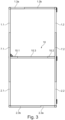
- den montierten Rahmen,
- Figur 4:
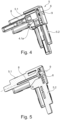
- einen Profilverbinder und
- Figur 5:
- eine Schnittansicht durch den Profilverbinder.
- Der in der
Figur 1 dargestellte Bausatz 3 für einen Rahmen umfasst eine erste Rahmenbaugruppe 1, eine zweite Rahmenbaugruppe 2, eine erste Verbindungsprofilleiste 7.1, eine zweite Verbindungsprofilleiste 7.2 und eine Mittelverbindungseinrichtung 10. - Die erste Rahmenbaugruppe 1 umfasst eine erste freie Profilleiste 1.1, eine zweite freie Profilleiste 1.2 sowie eine aus zwei Profilleisten 1.3a und 1.3b gebildete Verbindungseinrichtung 1.3 (siehe insbesondere auch
Figur 2 und3 ). - Die zweite Rahmenbaugruppe 2 umfasst eine erste freie Profilleiste 2.1, eine zweite freie Profilleiste 2.2 sowie eine aus zwei Profilleisten 2.3a und 2.3b gebildete Verbindungseinrichtung 2.3 (siehe auch
Figur 2 und3 ). Die freien Profilleisten 1.1, 1.2, 2.1 und 2.2 der Rahmenbaugruppen 1 und 2 sind jeweils über einen Profilverbinder 5 mit der zugehörigen Verbindungs-einrichtung 1.3 bzw. 2.3 verbunden. Ein solcher Profilverbinder wird mit Bezug zu denFiguren 4 und 5 weiter unten erläutert. - Die ersten freien Profilleisten 1.1 und 2.1 sind jeweils über ein erstes, eine Drehachse 4.1a aufweisendes Drehgelenk 4.1 mit der Verbindungseinrichtung 1.3, 2.3 verbunden (siehe auch
Figur 4 bezüglich der Drehachse 4.1a). Die zweiten freien Profilleisten 1.2 und 2.2 sind jeweils über ein zweites, eine Drehachse 4.2a aufweisendes Drehgelenk 4.2 mit der Verbindungseinrichtung 1.3, 2.3 verbunden. - In der
Figur 1 sind die Rahmenbaugruppen 1 und 2 in ihrer jeweiligen Ausgangsstellung gezeigt. In dieser Ausgangsstellung sind die freien Profilleisten 1.1, 1.2 beziehungsweise 2.1 und 2.2 zu der jeweiligen Verbindungseinrichtung 1.3, 2.3 und zueinander parallel ausgerichtet. - Die erste Verbindungsprofilleiste 7.1 und die zweite Verbindungsprofilleiste 7.2 sind jeweils als Außenprofilleiste ausgebildet.
- Die Mittelverbindungseinrichtung 10 umfasst zwei Außenprofilleisten 10.1 und 10.2 sowie eine Innenprofilleiste 10.3, die teleskopierbar in die beiden Außenprofilleisten 10.1 und 10.2 einsteckbar sind.
- In dem in
Figur 1 dargestellten Ausgangszustand können die einzelnen Baugruppen und Komponenten des Bausatzes einfach in einer Verpackung verstaut und einem Endkunden bereitgestellt werden. - In der
Figur 2 ist der Bausatz 3 derFigur 1 gezeigt, wobei sich die Rahmenbaugruppe 1 in einer Montagestellung befindet und sich die Rahmenbaugruppe 2 in einer Zwischenstellung zwischen der Ausgangsstellung und der Montagestellung befindet. - Die freien Profilleisten 2.1 und 2.2 der zweiten Rahmenbaugruppe 2 sind somit bereits um einige Grad aus ihrer Ausgangsstellung verschwenkt. In der Montagestellung, wie sie mit Bezug zu der Rahmenbaugruppe 1 dargestellt ist, sind die freien Profilleisten 1.1 und 1.2 jeweils in einem rechten Winkel zu der Verbindungseinrichtung 1.3 angeordnet. Aus
Figur 2 geht auch hervor, dass die Verbindungseinrichtung 1.3 aus zwei Profilleisten 1.3a und 1.3b besteht, die zur Einstellung der Breite des späteren Rahmens teleskopierbar zueinander sind. - Bei dem in
Figur 3 dargestellten Zustand des Rahmens sind die erste freie Profilleiste 1.1 der ersten Rahmenbaugruppe 1 und die erste freie Profilleiste 2.1 der zweiten Rahmenbaugruppe 2 von gegenüberliegenden Seiten in die erste Verbindungsprofilleiste 7.1 eingesteckt, während die zweite freie Profilleiste 1.2 der ersten Rahmenbaugruppe 1 und die zweite freie Profilleiste 2.2 der zweiten Rahmenbaugruppe 2 in die zweite Verbindungsprofilleiste 7.2 von gegenüberliegenden Seiten eingesteckt sind. Die Höhe des Rahmens kann somit durch Verschieben der Rahmenbaugruppe 1 und 2 entlang der Längserstreckung der Verbindungsprofilleisten 7.1 und 7.2 eingestellt werden. Zudem sind die beiden Verbindungsprofilleisten 7.1 und 7.2 über die Mittelverbindungseinrichtung 10 miteinander verbunden, so dass der Rahmen eine hohe Stabilität aufweist. - In den
Figuren 4 und 5 ist ein als Eckverbinder ausgebildeter Profilverbinder 5 dargestellt, welcher auch in den Rahmenbaugruppen derFiguren 1 bis 3 verwendet werden kann. Der Profilverbinder 5 weist einen ersten Verbindungsschenkel 5.1 und einen zweiten Verbindungsschenkel 5.2 auf, die jeweils abschnittsweise in eine Profilleiste eingesteckt werden können. Zwischen dem ersten Verbindungsschenkel 5.1 und dem zweiten Verbindungsschenkel 5.2 ist eine Drehachse 4.1a ausgebildet, so dass die Verbindungsschenkel 5.1, 5.2 aus einer Ausgangsstellung, in der die Verbindungsschenkel 5.1, 5.2 bzw. die Profilleisten in etwa parallel zueinander ausgerichtet sind, in eine Montagestellung verschwenkt werden können, in der die Verbindungsschenkel 5.1, 5.2 bzw. die Profilleisten in einem rechten Winkel zueinander angeordnet sind. In derFigur 4 befinden sich die Verbindungsschenkel 5.1 und 5.2 in der Montagestellung. - Wie insbesondere aus der Schnittdarstellung der
Figur 5 zu erkennen ist, ist in dem ersten Verbindungsschenkel 5.1 eine Aufnahme 8 ausgebildet, während in dem zweiten Verbindungsschenkel 5.2 ein Durchgangsloch 9 ausgebildet ist. - Die Aufnahme 8 und das Durchgangsloch 9 sind so an den Verbindungsschenkeln 5.1 und 5.2 ausgebildet, dass eine Schraube 6 durch das Durchgangsloch 9 hindurch in die Aufnahme 8 in der Montagestellung des Profilverbinders einschraubbar ist. Durch die Schraube 6 wird der erste Verbindungsschenkel 5.1 gegenüber dem zweiten Verbindungsschenkel 5.2 verspannt und somit auch in der Montagestellung gehalten. Mit der Schraube 6 kann somit auch jegliches Spiel zwischen den Verbindungsschenkeln 5.1 und 5.2 eliminiert werden, wodurch die Stabilität des Rahmens weiter erhöht wird.
-
- 1
- erste Rahmenbaugruppe
- 1.1
- erste freie Profilleiste
- 1.2
- zweite freie Profilleiste
- 1.3
- Verbindungseinrichtung
- 1.3a
- Profilleiste
- 1.3b
- Profilleiste
- 2
- zweite Rahmenbaugruppe
- 2.1
- erste freie Profilleiste
- 2.2
- zweite freie Profilleiste
- 2.3
- Verbindungseinrichtung
- 2.3a
- Profilleiste
- 2.3b
- Profilleiste
- 3
- Bausatz
- 4.1
- erstes Drehgelenk
- 4.1a
- Drehachse
- 4.2
- zweites Drehgelenk
- 4.2a
- Drehachse
- 5
- Profilverbinder
- 5.1
- erster Verbindungsschenkel
- 5.2
- zweiter Verbindungsschenkel
- 6
- Schraube
- 7.1
- erste Verbindungsprofilleiste
- 7.2
- zweite Verbindungsprofilleiste
- 8
- Aufnahme
- 9
- Durchgangsloch
- 10
- Mittelverbindungseinrichtung
- 10.1
- Außenprofilleiste
- 10.2
- Außenprofilleiste
- 10.3
- Innenprofilleiste
Claims (9)
- Bausatz (3) für einen Rahmen, insbesondere für einen Rahmen einer Insektenschutztür, mit• einer ersten vormontierten Rahmenbaugruppe (1),• einer zweiten vormontierten Rahmenbaugruppe (2),• mindestens einer ersten Verbindungsprofilleiste (7.1) und• mindestens einer zweiten Verbindungsprofilleiste (7.2),dadurch gekennzeichnet, dassdie beiden Rahmenbaugruppen (1, 2) jeweils- eine erste freie Profilleiste (1.1, 2.1),- eine zweite freie Profilleiste (1.2, 2.2) und- eine mindestens eine weitere Profilleiste (1.3a, 1.3b, 2.3a, 2.3b) aufweisende Verbindungseinrichtung (1.3, 2.3) umfassen, wobei• die erste freie Profilleiste (1.1, 2.1) an einem ersten Ende der Verbindungseinrichtung (1.3, 2.3) über ein erstes, eine Drehachse (4.1 a) aufweisendes Drehgelenk (4.1) mit der Verbindungseinrichtung (1.3, 2.3) verbunden ist,• die zweite freie Profilleiste (1.2, 2.2) an einem zweiten Ende der Verbindungseinrichtung (1.3, 2.3) über ein zweites, eine Drehachse (4.2 a) aufweisendes Drehgelenk (4.2) mit der Verbindungseinrichtung (1.3, 2.3) verbunden ist und• die Drehgelenke (4.1, 4.2) derart ausgebildet sind, dass- in einer Ausgangsstellung die zwei freien Profilleisten (1.1, 1.2, 2.1, 2.2) und die Verbindungseinrichtung (1.3, 2.3) parallel zueinander ausgerichtet sind und- die zwei freien Profilleisten (1.1, 1.2, 2.1, 2.2) durch Verschwenken zu der Verbindungseinrichtung (1.3, 2.3) um die jeweilige Drehachse (4.1a, 4.2a) in eine Montagestellung überführbar sind, in der die Rahmenbaugruppe (1, 2) U-förmig ausgebildet ist, wobei in der Montagestellungdie erste freie Profilleiste (1.1) der ersten Rahmenbaugruppe (1) einerseits und die erste freie Profilleiste (2.1) der zweiten Rahmenbaugruppe (2) andererseits mit der mindestens einen ersten Verbindungsprofilleiste (7.1) teleskopierbar verbindbar sind und die zweite freie Profilleiste (1.2) der ersten Rahmenbaugruppe (1) einerseits und die zweite freie Profilleiste (2.2) der zweiten Rahmenbaugruppe (2) andererseits mit der mindestens einen zweiten Verbindungsprofilleiste (7.2) teleskopierbar verbindbar sind, wobei der Bausatz (3) eine Verpackung umfasst, in der die zwei Rahmenbaugruppen (1, 2) in ihrer Ausgangsstellung angeordnet sind.
- Bausatz (3) nach Anspruch 1, wobei der Bausatz (3) eine Mittelverbindungseinrichtung (10) umfasst, mit der zwei parallel zueinander angeordnete Verbindungsprofilleisten (7.1, 7.2) verbindbar sind.
- Bausatz nach Anspruch 2, wobei die Mittelverbindungseinrichtung (10) mindestens eine Innenprofilleiste (10.3) und mindestens eine Außenprofilleiste (10.1, 10.2) umfasst, die teleskopierbar ineinander verschiebbar sind.
- Bausatz (3) nach einem der vorhergehenden Ansprüche, wobei genau eine erste Verbindungsprofilleiste (7.1) und genau eine zweite Verbindungsprofilleiste (7.2) vorgesehen sind, wobei in der Montagestellung sowohl die erste freie Profilleiste (1.1) der ersten Rahmenbaugruppe (1) als auch die erste freie Profilleiste (2.1) der zweiten Rahmenbaugruppe (2) und die erste Verbindungsprofilleiste (7.1) teleskopierbar ineinander steckbar sind, wobei in der Montagestellung sowohl die zweite freie Profilleiste (1.2) der ersten Rahmenbaugruppe (1) als auch die zweite freie Profilleiste (2.2) der zweiten Rahmenbaugruppe (2) und die zweite Verbindungsprofilleiste (7.2) teleskopierbar ineinander steckbar sind.
- Bausatz nach Anspruch 4, wobei die freien Profilleisten (1.1, 1.2, 2.1, 2.2) als Innenprofilleisten (1.2, 2.1) und die Verbindungsprofilleisten (7.1, 7 2) als Außenprofilleisten ausgebildet sind.
- Bausatz (3) nach einem der vorhergehenden Ansprüche, wobei im montierten Zustand des Rahmens die Drehachsen (4.1a, 4.2a) beider Rahmenbaugruppen (1, 2) parallel zueinander und orthogonal zu einer durch den Rahmen aufgespannten Ebene ausgerichtet sind.
- Bausatz (3) nach einem der vorhergehenden Ansprüche, wobei die freien Profilleisten (1.1, 1.2, 2.1, 2.2) der Rahmenbaugruppen (1, 2) in der Ausgangsstellung parallel und versetzt zueinander und zu der Verbindungseinrichtung (1.3, 2.3) angeordnet sind.
- Bausatz (3) nach einem der vorhergehenden Ansprüche, wobei die erste freie Profilleiste (1.1) und die zweite freie Profilleiste (1.2) jeweils über einen das Drehgelenk (4.1, 4.2) ausbildenden Profilverbinder (5) mit der Verbindungseinrichtung (1.3, 2.3) verbunden sind.
- Bausatz (3) nach Anspruch 8, wobei ein erster Verbindungsschenkel (5.1) eines Profilverbinders (5) in eine freie Profilleiste und ein zweiter, zu dem ersten Verbindungsschenkel (5.1) um die Drehachse (4.1a) verschwenkbarer Verbindungsschenkel (5.2) des Profilverbinders (5) in eine Profilleiste der Verbindungseinrichtung (1.3, 2.3) eingesteckt ist.
Priority Applications (2)
| Application Number | Priority Date | Filing Date | Title |
|---|---|---|---|
| EP23167568.7A EP4446558B1 (de) | 2023-04-12 | 2023-04-12 | Bausatz für einen rahmen |
| EP25171877.1A EP4567248A3 (de) | 2023-04-12 | 2023-04-12 | Bausatz für einen rahmen |
Applications Claiming Priority (1)
| Application Number | Priority Date | Filing Date | Title |
|---|---|---|---|
| EP23167568.7A EP4446558B1 (de) | 2023-04-12 | 2023-04-12 | Bausatz für einen rahmen |
Related Child Applications (1)
| Application Number | Title | Priority Date | Filing Date |
|---|---|---|---|
| EP25171877.1A Division EP4567248A3 (de) | 2023-04-12 | 2023-04-12 | Bausatz für einen rahmen |
Publications (3)
| Publication Number | Publication Date |
|---|---|
| EP4446558A1 EP4446558A1 (de) | 2024-10-16 |
| EP4446558B1 true EP4446558B1 (de) | 2025-04-30 |
| EP4446558C0 EP4446558C0 (de) | 2025-04-30 |
Family
ID=86006665
Family Applications (2)
| Application Number | Title | Priority Date | Filing Date |
|---|---|---|---|
| EP25171877.1A Pending EP4567248A3 (de) | 2023-04-12 | 2023-04-12 | Bausatz für einen rahmen |
| EP23167568.7A Active EP4446558B1 (de) | 2023-04-12 | 2023-04-12 | Bausatz für einen rahmen |
Family Applications Before (1)
| Application Number | Title | Priority Date | Filing Date |
|---|---|---|---|
| EP25171877.1A Pending EP4567248A3 (de) | 2023-04-12 | 2023-04-12 | Bausatz für einen rahmen |
Country Status (1)
| Country | Link |
|---|---|
| EP (2) | EP4567248A3 (de) |
Family Cites Families (7)
| Publication number | Priority date | Publication date | Assignee | Title |
|---|---|---|---|---|
| US498868A (en) * | 1893-06-06 | Pocket window-screen | ||
| US4279288A (en) | 1979-05-29 | 1981-07-21 | Lanier George G | Adjustable frame apparatus |
| AT394085B (de) * | 1990-07-30 | 1992-01-27 | Austria Metall | Eckwinkel zum einsetzen in hohlprofilleisten fuer rahmen von fenstern, tueren, fassadenteilen u. dgl. |
| DE102010062751A1 (de) * | 2010-12-09 | 2012-06-14 | Greiner Tool.Tec Gmbh | Eckverbindungsvorrichtung für Profile |
| PL3690177T3 (pl) | 2019-04-25 | 2021-10-25 | Büdenbender, Arnd | Łącznik profilowy z przegubem obrotowym |
| EP3835539B3 (de) | 2019-12-13 | 2026-04-22 | Bash-tec GmbH | Bausatz für einen rahmen |
| EP3910155B1 (de) | 2020-05-12 | 2026-04-15 | Bash-tec GmbH | Schutzvorrichtung |
-
2023
- 2023-04-12 EP EP25171877.1A patent/EP4567248A3/de active Pending
- 2023-04-12 EP EP23167568.7A patent/EP4446558B1/de active Active
Also Published As
| Publication number | Publication date |
|---|---|
| EP4446558A1 (de) | 2024-10-16 |
| EP4567248A3 (de) | 2025-08-20 |
| EP4446558C0 (de) | 2025-04-30 |
| EP4567248A2 (de) | 2025-06-11 |
Similar Documents
| Publication | Publication Date | Title |
|---|---|---|
| EP0789984A1 (de) | Rahmengestell für einen schaltschrank | |
| DE9212112U1 (de) | Tafel | |
| EP3683397B1 (de) | Rahmen mit drehgelenk aufweisenden profilverbindern | |
| EP3690177B1 (de) | Profilverbinder mit drehgelenk | |
| EP3835539B3 (de) | Bausatz für einen rahmen | |
| EP4202174B1 (de) | Bausatz für einen rahmen | |
| EP4567248A2 (de) | Bausatz für einen rahmen | |
| EP3875728B1 (de) | Profilverbinderbaugruppe und rahmen mit einer profilverbinderbaugruppe | |
| DE69525798T2 (de) | Ausrücksystem für eine Heckladeeinrichtung | |
| EP3730310A1 (de) | Rahmen mit drehgelenken | |
| DE60010832T2 (de) | Tischart welche mit mindestens einem faltbaren Fuss oder Untergestell versehen ist | |
| EP0383041A2 (de) | Aus einer Mehrzahl gerader Rahmenabschnitte bestehender Klapprahmen für Anzeigetafeln oder dergleichen | |
| DE2750503B2 (de) | Vorrichtung zum gegenseitigen Verbinden von Profilstäben | |
| DE102022124772B3 (de) | Zusammenklappbare Steighilfe mit Gelenkarretierung | |
| EP3431697A1 (de) | Beschattungsvorrichtung | |
| EP0893557A1 (de) | Zeltstangen-Einheit sowie Klemmeinrichtung dafür | |
| DE9217635U1 (de) | Zentralstütze eines zusammenlegbaren Schirms | |
| DE69521139T2 (de) | Faltbare trennwand | |
| DE202025003560U1 (de) | Spannrahmen für ein Insektenschutzgitter zum Einsetzen in eine Fensteröffnung | |
| EP3563009B1 (de) | Wandschirmverbindungseinrichtung zum gelenkigen verbinden von wandschirmen und wandschirmanordnung | |
| EP4501173A1 (de) | Vorrichtung zum parallelen ausschwenken einer plattform aus einem möbel sowie verbindungselement für eine solche vorrichtung | |
| DE20007695U1 (de) | Spiegelanordnung | |
| DE202020005587U1 (de) | Abstandhalter, Führungsschiene für einen Raffstore oder eine Jalousie sowie Raffstore und Jalousie | |
| DE9002051U1 (de) | Bauteil für Rahmen- und/oder Tragkonstruktionen | |
| DE9000341U1 (de) | Faltbares Displaygestell |
Legal Events
| Date | Code | Title | Description |
|---|---|---|---|
| PUAI | Public reference made under article 153(3) epc to a published international application that has entered the european phase |
Free format text: ORIGINAL CODE: 0009012 |
|
| STAA | Information on the status of an ep patent application or granted ep patent |
Free format text: STATUS: EXAMINATION IS IN PROGRESS |
|
| 17P | Request for examination filed |
Effective date: 20240328 |
|
| AK | Designated contracting states |
Kind code of ref document: A1 Designated state(s): AL AT BE BG CH CY CZ DE DK EE ES FI FR GB GR HR HU IE IS IT LI LT LU LV MC ME MK MT NL NO PL PT RO RS SE SI SK SM TR |
|
| GRAP | Despatch of communication of intention to grant a patent |
Free format text: ORIGINAL CODE: EPIDOSNIGR1 |
|
| STAA | Information on the status of an ep patent application or granted ep patent |
Free format text: STATUS: GRANT OF PATENT IS INTENDED |
|
| INTG | Intention to grant announced |
Effective date: 20241105 |
|
| GRAS | Grant fee paid |
Free format text: ORIGINAL CODE: EPIDOSNIGR3 |
|
| GRAA | (expected) grant |
Free format text: ORIGINAL CODE: 0009210 |
|
| STAA | Information on the status of an ep patent application or granted ep patent |
Free format text: STATUS: THE PATENT HAS BEEN GRANTED |
|
| AK | Designated contracting states |
Kind code of ref document: B1 Designated state(s): AL AT BE BG CH CY CZ DE DK EE ES FI FR GB GR HR HU IE IS IT LI LT LU LV MC ME MK MT NL NO PL PT RO RS SE SI SK SM TR |
|
| REG | Reference to a national code |
Ref country code: CH Ref legal event code: EP Ref country code: GB Ref legal event code: FG4D Free format text: NOT ENGLISH |
|
| REG | Reference to a national code |
Ref country code: IE Ref legal event code: FG4D Free format text: LANGUAGE OF EP DOCUMENT: GERMAN |
|
| REG | Reference to a national code |
Ref country code: DE Ref legal event code: R096 Ref document number: 502023000897 Country of ref document: DE |
|
| U01 | Request for unitary effect filed |
Effective date: 20250519 |
|
| U07 | Unitary effect registered |
Designated state(s): AT BE BG DE DK EE FI FR IT LT LU LV MT NL PT RO SE SI Effective date: 20250523 |
|
| PG25 | Lapsed in a contracting state [announced via postgrant information from national office to epo] |
Ref country code: ES Free format text: LAPSE BECAUSE OF FAILURE TO SUBMIT A TRANSLATION OF THE DESCRIPTION OR TO PAY THE FEE WITHIN THE PRESCRIBED TIME-LIMIT Effective date: 20250430 |
|
| PG25 | Lapsed in a contracting state [announced via postgrant information from national office to epo] |
Ref country code: GR Free format text: LAPSE BECAUSE OF FAILURE TO SUBMIT A TRANSLATION OF THE DESCRIPTION OR TO PAY THE FEE WITHIN THE PRESCRIBED TIME-LIMIT Effective date: 20250731 Ref country code: NO Free format text: LAPSE BECAUSE OF FAILURE TO SUBMIT A TRANSLATION OF THE DESCRIPTION OR TO PAY THE FEE WITHIN THE PRESCRIBED TIME-LIMIT Effective date: 20250730 |
|
| PG25 | Lapsed in a contracting state [announced via postgrant information from national office to epo] |
Ref country code: PL Free format text: LAPSE BECAUSE OF FAILURE TO SUBMIT A TRANSLATION OF THE DESCRIPTION OR TO PAY THE FEE WITHIN THE PRESCRIBED TIME-LIMIT Effective date: 20250430 |
|
| PG25 | Lapsed in a contracting state [announced via postgrant information from national office to epo] |
Ref country code: HR Free format text: LAPSE BECAUSE OF FAILURE TO SUBMIT A TRANSLATION OF THE DESCRIPTION OR TO PAY THE FEE WITHIN THE PRESCRIBED TIME-LIMIT Effective date: 20250430 |
|
| PG25 | Lapsed in a contracting state [announced via postgrant information from national office to epo] |
Ref country code: RS Free format text: LAPSE BECAUSE OF FAILURE TO SUBMIT A TRANSLATION OF THE DESCRIPTION OR TO PAY THE FEE WITHIN THE PRESCRIBED TIME-LIMIT Effective date: 20250731 |
|
| PG25 | Lapsed in a contracting state [announced via postgrant information from national office to epo] |
Ref country code: IS Free format text: LAPSE BECAUSE OF FAILURE TO SUBMIT A TRANSLATION OF THE DESCRIPTION OR TO PAY THE FEE WITHIN THE PRESCRIBED TIME-LIMIT Effective date: 20250830 |
|
| PG25 | Lapsed in a contracting state [announced via postgrant information from national office to epo] |
Ref country code: SM Free format text: LAPSE BECAUSE OF FAILURE TO SUBMIT A TRANSLATION OF THE DESCRIPTION OR TO PAY THE FEE WITHIN THE PRESCRIBED TIME-LIMIT Effective date: 20250430 |
|
| PG25 | Lapsed in a contracting state [announced via postgrant information from national office to epo] |
Ref country code: CZ Free format text: LAPSE BECAUSE OF FAILURE TO SUBMIT A TRANSLATION OF THE DESCRIPTION OR TO PAY THE FEE WITHIN THE PRESCRIBED TIME-LIMIT Effective date: 20250430 |
|
| U1N | Appointed representative for the unitary patent procedure changed after the registration of the unitary effect |
Representative=s name: FEUCKER, MAX MARTIN; DE |
|
| PG25 | Lapsed in a contracting state [announced via postgrant information from national office to epo] |
Ref country code: SK Free format text: LAPSE BECAUSE OF FAILURE TO SUBMIT A TRANSLATION OF THE DESCRIPTION OR TO PAY THE FEE WITHIN THE PRESCRIBED TIME-LIMIT Effective date: 20250430 |
|
| PLBE | No opposition filed within time limit |
Free format text: ORIGINAL CODE: 0009261 |
|
| STAA | Information on the status of an ep patent application or granted ep patent |
Free format text: STATUS: NO OPPOSITION FILED WITHIN TIME LIMIT |
|
| REG | Reference to a national code |
Ref country code: CH Ref legal event code: L10 Free format text: ST27 STATUS EVENT CODE: U-0-0-L10-L00 (AS PROVIDED BY THE NATIONAL OFFICE) Effective date: 20260311 |
|
| 26N | No opposition filed |
Effective date: 20260202 |
|
| REG | Reference to a national code |
Ref country code: CH Ref legal event code: U11 Free format text: ST27 STATUS EVENT CODE: U-0-0-U10-U11 (AS PROVIDED BY THE NATIONAL OFFICE) Effective date: 20260501 |
|
| U20 | Renewal fee for the european patent with unitary effect paid |
Year of fee payment: 4 Effective date: 20260409 |
|
| PGFP | Annual fee paid to national office [announced via postgrant information from national office to epo] |
Ref country code: CH Payment date: 20260501 Year of fee payment: 4 |