EP4446602A1 - Palier à roulement - Google Patents
Palier à roulement Download PDFInfo
- Publication number
- EP4446602A1 EP4446602A1 EP21967122.9A EP21967122A EP4446602A1 EP 4446602 A1 EP4446602 A1 EP 4446602A1 EP 21967122 A EP21967122 A EP 21967122A EP 4446602 A1 EP4446602 A1 EP 4446602A1
- Authority
- EP
- European Patent Office
- Prior art keywords
- annular member
- bearing
- inner ring
- rolling bearing
- outer ring
- Prior art date
- Legal status (The legal status is an assumption and is not a legal conclusion. Google has not performed a legal analysis and makes no representation as to the accuracy of the status listed.)
- Withdrawn
Links
Images


Classifications
-
- F—MECHANICAL ENGINEERING; LIGHTING; HEATING; WEAPONS; BLASTING
- F16—ENGINEERING ELEMENTS AND UNITS; GENERAL MEASURES FOR PRODUCING AND MAINTAINING EFFECTIVE FUNCTIONING OF MACHINES OR INSTALLATIONS; THERMAL INSULATION IN GENERAL
- F16C—SHAFTS; FLEXIBLE SHAFTS; ELEMENTS OR CRANKSHAFT MECHANISMS; ROTARY BODIES OTHER THAN GEARING ELEMENTS; BEARINGS
- F16C19/00—Bearings with rolling contact, for exclusively rotary movement
- F16C19/02—Bearings with rolling contact, for exclusively rotary movement with bearing balls essentially of the same size in one or more circular rows
- F16C19/04—Bearings with rolling contact, for exclusively rotary movement with bearing balls essentially of the same size in one or more circular rows for radial load mainly
- F16C19/06—Bearings with rolling contact, for exclusively rotary movement with bearing balls essentially of the same size in one or more circular rows for radial load mainly with a single row or balls
-
- F—MECHANICAL ENGINEERING; LIGHTING; HEATING; WEAPONS; BLASTING
- F16—ENGINEERING ELEMENTS AND UNITS; GENERAL MEASURES FOR PRODUCING AND MAINTAINING EFFECTIVE FUNCTIONING OF MACHINES OR INSTALLATIONS; THERMAL INSULATION IN GENERAL
- F16C—SHAFTS; FLEXIBLE SHAFTS; ELEMENTS OR CRANKSHAFT MECHANISMS; ROTARY BODIES OTHER THAN GEARING ELEMENTS; BEARINGS
- F16C19/00—Bearings with rolling contact, for exclusively rotary movement
- F16C19/52—Bearings with rolling contact, for exclusively rotary movement with devices affected by abnormal or undesired conditions
-
- F—MECHANICAL ENGINEERING; LIGHTING; HEATING; WEAPONS; BLASTING
- F16—ENGINEERING ELEMENTS AND UNITS; GENERAL MEASURES FOR PRODUCING AND MAINTAINING EFFECTIVE FUNCTIONING OF MACHINES OR INSTALLATIONS; THERMAL INSULATION IN GENERAL
- F16C—SHAFTS; FLEXIBLE SHAFTS; ELEMENTS OR CRANKSHAFT MECHANISMS; ROTARY BODIES OTHER THAN GEARING ELEMENTS; BEARINGS
- F16C33/00—Parts of bearings; Special methods for making bearings or parts thereof
- F16C33/30—Parts of ball or roller bearings
- F16C33/58—Raceways; Race rings
- F16C33/583—Details of specific parts of races
- F16C33/586—Details of specific parts of races outside the space between the races, e.g. end faces or bore of inner ring
-
- F—MECHANICAL ENGINEERING; LIGHTING; HEATING; WEAPONS; BLASTING
- F16—ENGINEERING ELEMENTS AND UNITS; GENERAL MEASURES FOR PRODUCING AND MAINTAINING EFFECTIVE FUNCTIONING OF MACHINES OR INSTALLATIONS; THERMAL INSULATION IN GENERAL
- F16C—SHAFTS; FLEXIBLE SHAFTS; ELEMENTS OR CRANKSHAFT MECHANISMS; ROTARY BODIES OTHER THAN GEARING ELEMENTS; BEARINGS
- F16C33/00—Parts of bearings; Special methods for making bearings or parts thereof
- F16C33/30—Parts of ball or roller bearings
- F16C33/66—Special parts or details in view of lubrication
-
- F—MECHANICAL ENGINEERING; LIGHTING; HEATING; WEAPONS; BLASTING
- F16—ENGINEERING ELEMENTS AND UNITS; GENERAL MEASURES FOR PRODUCING AND MAINTAINING EFFECTIVE FUNCTIONING OF MACHINES OR INSTALLATIONS; THERMAL INSULATION IN GENERAL
- F16C—SHAFTS; FLEXIBLE SHAFTS; ELEMENTS OR CRANKSHAFT MECHANISMS; ROTARY BODIES OTHER THAN GEARING ELEMENTS; BEARINGS
- F16C33/00—Parts of bearings; Special methods for making bearings or parts thereof
- F16C33/30—Parts of ball or roller bearings
- F16C33/66—Special parts or details in view of lubrication
- F16C33/6637—Special parts or details in view of lubrication with liquid lubricant
- F16C33/6659—Details of supply of the liquid to the bearing, e.g. passages or nozzles
-
- F—MECHANICAL ENGINEERING; LIGHTING; HEATING; WEAPONS; BLASTING
- F16—ENGINEERING ELEMENTS AND UNITS; GENERAL MEASURES FOR PRODUCING AND MAINTAINING EFFECTIVE FUNCTIONING OF MACHINES OR INSTALLATIONS; THERMAL INSULATION IN GENERAL
- F16C—SHAFTS; FLEXIBLE SHAFTS; ELEMENTS OR CRANKSHAFT MECHANISMS; ROTARY BODIES OTHER THAN GEARING ELEMENTS; BEARINGS
- F16C33/00—Parts of bearings; Special methods for making bearings or parts thereof
- F16C33/72—Sealings
- F16C33/76—Sealings of ball or roller bearings
- F16C33/78—Sealings of ball or roller bearings with a diaphragm, disc, or ring, with or without resilient members
- F16C33/784—Sealings of ball or roller bearings with a diaphragm, disc, or ring, with or without resilient members mounted to a groove in the inner surface of the outer race and extending toward the inner race
- F16C33/7843—Sealings of ball or roller bearings with a diaphragm, disc, or ring, with or without resilient members mounted to a groove in the inner surface of the outer race and extending toward the inner race with a single annular sealing disc
- F16C33/7853—Sealings of ball or roller bearings with a diaphragm, disc, or ring, with or without resilient members mounted to a groove in the inner surface of the outer race and extending toward the inner race with a single annular sealing disc with one or more sealing lips to contact the inner race
-
- F—MECHANICAL ENGINEERING; LIGHTING; HEATING; WEAPONS; BLASTING
- F16—ENGINEERING ELEMENTS AND UNITS; GENERAL MEASURES FOR PRODUCING AND MAINTAINING EFFECTIVE FUNCTIONING OF MACHINES OR INSTALLATIONS; THERMAL INSULATION IN GENERAL
- F16C—SHAFTS; FLEXIBLE SHAFTS; ELEMENTS OR CRANKSHAFT MECHANISMS; ROTARY BODIES OTHER THAN GEARING ELEMENTS; BEARINGS
- F16C33/00—Parts of bearings; Special methods for making bearings or parts thereof
- F16C33/72—Sealings
- F16C33/76—Sealings of ball or roller bearings
- F16C33/78—Sealings of ball or roller bearings with a diaphragm, disc, or ring, with or without resilient members
- F16C33/7869—Sealings of ball or roller bearings with a diaphragm, disc, or ring, with or without resilient members mounted with a cylindrical portion to the inner surface of the outer race and having a radial portion extending inward
- F16C33/7873—Sealings of ball or roller bearings with a diaphragm, disc, or ring, with or without resilient members mounted with a cylindrical portion to the inner surface of the outer race and having a radial portion extending inward with a single sealing ring of generally L-shaped cross-section
- F16C33/7876—Sealings of ball or roller bearings with a diaphragm, disc, or ring, with or without resilient members mounted with a cylindrical portion to the inner surface of the outer race and having a radial portion extending inward with a single sealing ring of generally L-shaped cross-section with sealing lips
-
- F—MECHANICAL ENGINEERING; LIGHTING; HEATING; WEAPONS; BLASTING
- F16—ENGINEERING ELEMENTS AND UNITS; GENERAL MEASURES FOR PRODUCING AND MAINTAINING EFFECTIVE FUNCTIONING OF MACHINES OR INSTALLATIONS; THERMAL INSULATION IN GENERAL
- F16C—SHAFTS; FLEXIBLE SHAFTS; ELEMENTS OR CRANKSHAFT MECHANISMS; ROTARY BODIES OTHER THAN GEARING ELEMENTS; BEARINGS
- F16C41/00—Other accessories, e.g. devices integrated in the bearing not relating to the bearing function as such
- F16C41/002—Conductive elements, e.g. to prevent static electricity
-
- F—MECHANICAL ENGINEERING; LIGHTING; HEATING; WEAPONS; BLASTING
- F16—ENGINEERING ELEMENTS AND UNITS; GENERAL MEASURES FOR PRODUCING AND MAINTAINING EFFECTIVE FUNCTIONING OF MACHINES OR INSTALLATIONS; THERMAL INSULATION IN GENERAL
- F16C—SHAFTS; FLEXIBLE SHAFTS; ELEMENTS OR CRANKSHAFT MECHANISMS; ROTARY BODIES OTHER THAN GEARING ELEMENTS; BEARINGS
- F16C2380/00—Electrical apparatus
- F16C2380/26—Dynamo-electric machines or combinations therewith, e.g. electro-motors and generators
Definitions
- the present disclosure relates to rolling bearings.
- Patent Document 1 discloses a rolling bearing having an anti-electrolytic corrosion function as a bearing that supports a rotating shaft of a motor.
- This rolling bearing includes an outer ring, an inner ring, a plurality of balls arranged between the outer ring and the inner ring, and sealing plates that close the space between the outer ring and the inner ring from both sides in an axial direction.
- Each sealing plate includes a holder fixed to the outer ring and a sliding member held by the holder and is in sliding contact with the outer peripheral surface of the inner ring.
- the sliding member is made of a woven fabric containing electrically conductive fibers.
- Patent Document 1 Japanese Unexamined Patent Application Publication No. 2010-106971 ( JP 2010-106971 A )
- a rolling bearing of the present disclosure includes: an outer ring; an inner ring; a plurality of rolling elements arranged between the outer ring and the inner ring; and an electrically conductive annular member attached to an axial end of the outer ring, the annular member separating a bearing internal space where the rolling elements are located from a bearing external space that is outside the bearing internal space in an axial direction.
- the annular member includes an electrically conductive elastic lip portion that contacts the inner ring.
- An oil channel connecting the bearing internal space and the bearing external space is provided in the annular member.
- the rolling bearing of the present disclosure can prevent electrolytic corrosion on raceway surfaces on which the rolling elements roll. Moreover, it is possible to obtain a rolling bearing that can be used even when oil is used.
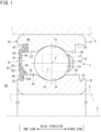
- FIG. 1 is a sectional view showing an example of a rolling bearing of the present disclosure.
- a rolling bearing 10 shown in FIG. 1 supports a rotating shaft S of a motor mounted on a battery electric vehicle or a hybrid electric vehicle.
- the rotating shaft S is shown in hidden outline (long dashed double-short dashed line).
- the rolling bearing 10 includes one outer ring 11, one inner ring 12, a plurality of rolling elements, and one annular member 15.
- the rolling elements are balls 13, and the rolling bearing 10 is a deep groove ball bearing.
- the outer ring 11 is attached to a housing H of the motor, and the inner ring 12 is fitted and fixed on the rotating shaft S.
- the housing H is shown in hidden outline (long dashed double-short dashed line).
- the outer ring 11 is a stationary ring
- the inner ring 12 is a rotating ring.
- the direction of the rolling bearing 10 of the present disclosure will be described.
- the outer ring 11 and the inner ring 12 are arranged concentrically, and their centerline coincides with a centerline C of the rolling bearing 10.
- a direction along the centerline C and a direction parallel to the centerline C are defined as the "axial direction.”
- a direction perpendicular to the centerline C is defined as the "radial direction.”
- a direction along a circle about the centerline C is defined as the "circumferential direction.”
- the annular member 15 is provided only on the one side in the axial direction of the rolling bearing 10.
- the annular member 15 is not provided on the other side in the axial direction of the rolling bearing 10.
- a bearing internal space K1 where the balls 13 are present in an annular space J between the outer ring 11 and the inner ring 12 is open on the other side in the axial direction.
- oil passes through the annular space J of the rolling bearing 10.
- the direction in which oil flows may be a direction from the one side in the axial direction toward the other side in the axial direction, or may be the opposite direction.
- Shoulders 22 are formed on both sides in the axial direction of the outer ring raceway 21.
- a recess 23 is provided on the one side in the axial direction of the outer ring 11.
- the recess 23 is in the shape of a groove that is continuous in the circumferential direction, and the annular member 15 is placed in the recess 23.
- a recess 23 is also formed on the other side in the axial direction of the outer ring 11, this recess 23 may be omitted.
- Shoulders 32 are formed on both sides in the axial direction of the inner ring raceway 31.
- a circumferential groove 33 is formed in an end on the one side in the axial direction of the inner ring 12.
- An elastic lip portion 45 that is part of the annular member 15 contacts the circumferential groove 33.
- a circumferential groove 33 is also formed on the other side in the axial direction of the inner ring 12, this circumferential groove 33 may be omitted.
- the balls 13 are arranged between the outer ring 11 and the inner ring 12, and are in rolling contact with the outer ring raceway 21 and the inner ring raceway 31.
- the plurality of balls 13 is held spaced apart from each other in the circumferential direction by an annular cage 14.
- the cage 14 includes an annular body 16 provided on the other side in the axial direction of the balls 13, and a plurality of prongs (pillars) 17 provided so as to extend from the annular body 16 toward the one side in the axial direction.
- Spaces located on the one side in the axial direction of the annular body 16 and each located between circumferentially adjacent two of the prongs 17, 17 are pockets 18 that hold the balls 13.
- the pockets 18 are open on the one side in the axial direction.
- a current generated by the motor may flow through the rolling bearing 10.
- the annular member 15 is a member that forms a path for the current flowing through the rolling bearing 10. In other words, the annular member 15 is part of the path for the current flowing through the rolling bearing 10. Therefore, the entire annular member 15 is electrically conductive.
- the current generated by the motor flows in the rolling bearing 10 through the annular member 15 rather than flowing in the rolling bearing 10 through the balls 13.
- An oil film is formed between the balls 13 and each of the inner ring raceway 31 and the outer ring raceway 21.
- the oil film functions as an insulating film, but if the oil film is partially broken, electricity may flow between the balls 13 and the inner ring raceway 31 (outer ring raceway 21).
- the annular member 15 prevents the inner ring 12 (or outer ring 11) from being electrically charged. Electricity can thus be prevented in advance from flowing between the balls 13 and the inner ring raceway 31 (outer ring raceway 21) even if the oil film is partially broken. As a result, it is possible to prevent electrolytic corrosion on the outer ring raceway 21 and the inner ring raceway 31 due to a current flowing in the rolling bearing 10 through the balls 13.
- the annular member 15 is attached to an axial end of the outer ring 11.
- the annular member 15 is fixed to the outer ring 11 with a radially outer end 49 of the annular member 15 fitted in the recess 23 of the outer ring 11.
- the annular member 15 has an annular shape.
- the annular member 15 separates the bearing internal space K1 where the balls 13 are located from a bearing external space K2 that is outside the bearing internal space K1 in the axial direction.
- the annular member 15 closes the bearing internal space K1 from the one side in the axial direction except for part of the bearing internal space K1 (oil channels that will be described later).
- the annular member 15 can thus function as a sealing member that reduces entry of foreign matter such as wear debris generated in the bearing external space K2 on the one side in the axial direction.
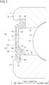
- FIG. 2 is a sectional view showing the annular member 15 and its surrounding area.
- the annular member 15 includes a core (metal ring) 41 made of metal and an elastic member 42 made of electrically conductive rubber.
- the core 41 has an annular shape and has a bent portion 43 on its radially inner side.
- the elastic member 42 covers the core 41.
- the elastic member 42 is made of synthetic rubber. The synthetic rubber has been mixed with electrically conductive carbon black or metal powder. The elastic member 42 is thus made electrically conductive.
- the core 41 is made of, for example, stainless steel.
- the elastic member 42 includes a body portion 44 that covers the core 41, and the elastic lip portion 45 provided so as to extend radially inward from the body portion 44.
- the elastic lip portion 45 is part of the elastic member 42 and is therefore electrically conductive.
- the elastic lip portion 45 contacts the inner ring 12. In the form shown in FIG. 2 , the elastic lip portion 45 contacts a wall surface 33a of the circumferential groove 33 in the inner ring 12 that faces in the axial direction.
- the core 41 includes an annular plate portion 46 and a tilted portion 47 extending from a radially inner end 46a of the plate portion 46.
- the tilted portion 47 extends from the end 46a such that the radially inner side of the tilted portion 47 is located further into the bearing internal space K1.
- the elastic member 42 includes a covering portion 48 that covers the tilted portion 47.
- the covering portion 48 may have a lip portion that contacts the shoulder 32 of the inner ring 12, but in the form shown in FIG. 2 , a clearance e is formed between the covering portion 48 and the shoulder 32 of the inner ring 12.
- the elastic lip portion 45 is provided so as to extend radially inward from the covering portion 48.
- An adhesive is provided as a coating film on the surface of the core 41, and the elastic member 42 covers the core 41 via the adhesive.
- the electrical resistance value of the core 41 including the coating film (adhesive) is lower than the electrical resistance value of the elastic member 42. Therefore, the core 41 is also actively utilized as an electrically conductive member.
- the volume resistivity of the elastic member 42 is preferably 100 ⁇ cm or less, more preferably 20 ⁇ cm or less.
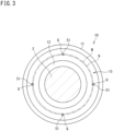
- FIG. 3 is a diagram of the rolling bearing 10 shown in FIGS. 1 and 2 as viewed in the axial direction.
- a plurality of holes 51 connecting the bearing internal space K1 and the bearing external space K2 is formed as oil channels in the annular member 15. Oil can pass through the holes 51.
- the holes 51 extend through the core 41 and the elastic member 42 in the axial direction.
- the plurality of holes 51 is provided at intervals in the circumferential direction. In the form shown in FIG. 3 , the plurality of (four) holes 51 is provided at equal intervals in the circumferential direction.
- the holes 51 are circular holes.
- An imaginary circle passing through the centers P (see FIG. 1 ) of the plurality of balls 13 is herein defined as a pitch circle M (see FIG. 3 ).
- the centers Q of the holes 51 are located outside the pitch circle M in the radial direction.
- the four holes 51 are located along one imaginary circle N about the centerline C of the rolling bearing 10.
- the imaginary circle N has a larger radius than the pitch circle M.
- the holes 51 may be arranged in a manner different from that shown in the figure.
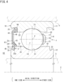
- FIG. 4 is a sectional view of the rolling bearing 10, illustrating a modification of the annular member 15.
- FIG. 5 is an illustration of the annular member 15 of the rolling bearing 10 shown in FIG. 4 as viewed in the axial direction.
- the oil channels are cuts 52 formed in the annular member 15.
- the cuts 52 are provided in an inner peripheral edge region V of the annular member 15 that includes the elastic lip portion 45.
- the elastic lip portion 45 is provided along the circumferential direction, and the cuts 52 are provided in part of the elastic lip portion 45.
- the cuts 52 have such a shape that they extend through the elastic lip portion 45 in the axial direction.
- the plurality of cuts 52 is provided at intervals in the circumferential direction. In the form shown in FIG. 5 , four cuts 52 are provided at equal intervals in the circumferential direction.
- FIG. 6 is an enlarged sectional view showing the cut 52 forming the oil channel and its surrounding area.
- the radial formation range of the cut 52 in the elastic lip portion 45 is the range of the circumferential groove 33 provided in the inner ring 12.
- a radially outer end 52e of the cut 52 coincides with an imaginary cylindrical plane I passing through the shoulder 32 of the inner ring 12, or is located radially inward of the imaginary cylindrical plane I.
- the radial formation range of the cut 52 may be different from the range described above.
- the radially outer end 52e of the cut 52 may be located radially outward of the imaginary cylindrical plane I.
- the cut 52 may be formed in part (inner peripheral end) of the core 41 in addition to the elastic lip portion 45.
- the rolling bearing 10 of each of the above forms includes the annular member 15 attached to the axial end of the outer ring 11.
- the entire annular member 15 is electrically conductive.
- the annular member 15 separates the bearing internal space K1 from the bearing external space K2.
- the annular member 15 includes the electrically conductive elastic lip portion 45 that contacts the inner ring 12.
- the oil channels connecting the bearing internal space K1 and the bearing external space K2 are provided in the annular member 15.
- the oil channels are the holes 51.
- the oil channels are the cuts 52.
- the rolling bearing 10 allows electricity built on the inner ring 12 to flow to the outer ring 11 through the electrically conductive annular member 15. This can prevent electrolytic corrosion on the raceway surfaces on which the balls 13 roll (outer ring raceway 21, inner ring raceway 31). Moreover, when oil circulates in a device through the rolling bearing 10, the oil channels can provide a flow path for the oil. When oil around the rolling bearing 10 is used to lubricate the rolling bearing 10, the oil can pass through the oil channels. Therefore, the oil will not stagnate in the bearing internal space K1, which can reduce an increase in stirring resistance during rotation of the bearing. It is thus possible to obtain the rolling bearing 10 that can be used even when oil is used.
- the annular member 15 is provided only on the one side in the axial direction, and the annular space J between the outer ring 11 and the inner ring 12 is open on the other side in the axial direction. Therefore, oil can be supplied from the other side in the axial direction to the bearing internal space K1 where the balls 13 are provided.
- the oil channels holes 51, cuts 52
- the amount of supplied oil in the bearing internal space K1 will not become too much, which prevents an increase in stirring resistance of the rolling bearing 10.
- the oil channels are the holes 51 extending through the annular member 15.
- the holes 51 centers Q of the holes 51
- the holes 51 are provided radially outward of the pitch circle M of the plurality of balls 13. Since the holes 51 are provided closer to the radially outer side of the annular member 15, the oil is more likely to pass through the holes 51.
- the oil channels are the cuts 52 provided in the inner peripheral edge region V of the annular member 15 that includes the elastic lip portion 45.
- the oil channels are formed by the cuts 52, and the contact range between the elastic lip portion 45 and the inner ring 12 is reduced, so that sliding resistance can be reduced.
- the circumferential groove 33 is formed in the axial end of the inner ring 12, and the elastic lip portion 45 is placed in the circumferential groove 33.
- each cut 52 is provided in a part of the elastic lip portion 45 that is located in the range of the circumferential groove 33.
- the annular member 15 has, in its inner periphery, the covering portion 48 that faces the shoulder 32 of the inner ring 12 with the clearance e therebetween. The amount of oil passing through is limited by the clearance e and the cuts 52.
- the above embodiment illustrates the case where the outer ring 11 is a stationary ring and the inner ring 12 is a rotating ring.
- the outer ring 11 may be a rotating ring and the inner ring 12 may be a stationary ring.
- the annular member 15 is attached to the axial end of the outer ring 11, and the configuration of the annular member 15 is the same as that in the form shown in FIG. 1 or 4 .
- the annular member 15 may be provided at both axial ends of the rolling bearing 10.
- the rolling bearing 10 is a deep groove ball bearing.
- the rolling bearing 10 may be an angular contact ball bearing, a roller bearing whose rolling elements are rollers, etc.
Landscapes
- Engineering & Computer Science (AREA)
- General Engineering & Computer Science (AREA)
- Mechanical Engineering (AREA)
- Rolling Contact Bearings (AREA)
Applications Claiming Priority (1)
| Application Number | Priority Date | Filing Date | Title |
|---|---|---|---|
| PCT/JP2021/044896 WO2023105618A1 (fr) | 2021-12-07 | 2021-12-07 | Palier à roulement |
Publications (2)
| Publication Number | Publication Date |
|---|---|
| EP4446602A1 true EP4446602A1 (fr) | 2024-10-16 |
| EP4446602A4 EP4446602A4 (fr) | 2025-02-19 |
Family
ID=86729876
Family Applications (1)
| Application Number | Title | Priority Date | Filing Date |
|---|---|---|---|
| EP21967122.9A Withdrawn EP4446602A4 (fr) | 2021-12-07 | 2021-12-07 | Palier à roulement |
Country Status (5)
| Country | Link |
|---|---|
| US (1) | US20240418222A1 (fr) |
| EP (1) | EP4446602A4 (fr) |
| JP (1) | JP7694705B2 (fr) |
| CN (1) | CN118355203A (fr) |
| WO (1) | WO2023105618A1 (fr) |
Family Cites Families (12)
| Publication number | Priority date | Publication date | Assignee | Title |
|---|---|---|---|---|
| JPS4618725Y1 (fr) * | 1967-06-03 | 1971-06-30 | ||
| JP4243698B2 (ja) * | 2003-03-17 | 2009-03-25 | Nok株式会社 | 密封装置 |
| JP2007270873A (ja) * | 2006-03-30 | 2007-10-18 | Jtekt Corp | 密封装置 |
| DE102007052104A1 (de) * | 2007-10-31 | 2009-06-25 | Schaeffler Kg | Dichtelement für ein Lager, insbesondere für ein Wälzlager |
| JP2010007738A (ja) * | 2008-06-25 | 2010-01-14 | Nsk Ltd | 転がり軸受 |
| JP2010106971A (ja) | 2008-10-30 | 2010-05-13 | Ntn Corp | 転がり軸受 |
| JP6789739B2 (ja) * | 2016-09-08 | 2020-11-25 | Ntn株式会社 | シール付軸受 |
| JP6437993B2 (ja) * | 2016-12-22 | 2018-12-12 | 株式会社Subaru | 軸受構造 |
| US10931179B2 (en) * | 2018-03-20 | 2021-02-23 | Aktiebolaget Skf | Fiber grounding brush |
| US10578164B1 (en) * | 2018-09-26 | 2020-03-03 | Schaeffleer Technologies Ag & Co. Kg | Bearing having integrated soft connected grounding device |
| CN110454505B (zh) * | 2019-07-15 | 2024-09-27 | 舍弗勒技术股份两合公司 | 密封装置和轴承组件 |
| IT202000005578A1 (it) * | 2020-03-17 | 2021-09-17 | Skf Ab | Assieme conduttivo ad attrito ridotto per cuscinetti |
-
2021
- 2021-12-07 CN CN202180104648.1A patent/CN118355203A/zh active Pending
- 2021-12-07 WO PCT/JP2021/044896 patent/WO2023105618A1/fr not_active Ceased
- 2021-12-07 EP EP21967122.9A patent/EP4446602A4/fr not_active Withdrawn
- 2021-12-07 US US18/706,276 patent/US20240418222A1/en active Pending
- 2021-12-07 JP JP2023565722A patent/JP7694705B2/ja active Active
Also Published As
| Publication number | Publication date |
|---|---|
| EP4446602A4 (fr) | 2025-02-19 |
| WO2023105618A1 (fr) | 2023-06-15 |
| CN118355203A (zh) | 2024-07-16 |
| US20240418222A1 (en) | 2024-12-19 |
| JPWO2023105618A1 (fr) | 2023-06-15 |
| JP7694705B2 (ja) | 2025-06-18 |
Similar Documents
| Publication | Publication Date | Title |
|---|---|---|
| EP2386772B1 (fr) | Roulement à rouleaux avec lubrification interne | |
| CN108397476B (zh) | 滚珠轴承 | |
| US7771122B2 (en) | Cage for rolling bearing and rolling bearing having the same | |
| US20230220882A1 (en) | Bearing device with integrated electrical insulation, in particular for an electric motor or machine | |
| US20210348645A1 (en) | Bearing assembly | |
| US20200096047A1 (en) | Bearing having integrated soft connected grounding device | |
| US9353795B2 (en) | Rolling bearing | |
| US20110293212A1 (en) | Roller bearing | |
| WO2013028284A1 (fr) | Cage de palier pour un ensemble roulement à rouleaux | |
| EP4446602A1 (fr) | Palier à roulement | |
| JP2020041659A (ja) | 玉軸受 | |
| JP6267906B2 (ja) | 玉軸受用冠型保持器および玉軸受 | |
| JP2015064056A (ja) | 玉軸受用保持器及び玉軸受 | |
| CN113107968A (zh) | 具有导电介质的轴承 | |
| CN215596216U (zh) | 导电导油组件、轴承及电桥驱动系统 | |
| EP3839279A1 (fr) | Rouleaux équipés d'un dispositif de retenue et structure de support d'engrenage planétaire | |
| US20250286427A1 (en) | Bearing device with integrated electric insulation, notably for an electric motor or machine | |
| US20260085726A1 (en) | Bearing device with integrated electric insulation, in particular for an electric machine or motor, and associated manufacturing methods | |
| US20250283512A1 (en) | Bearing device with integrated electrical insulation, notably for an electric motor or machine | |
| CN109818447B (zh) | 用于电机的端罩及其形成方法 | |
| US20240204605A1 (en) | Grounding brush and associated assembly | |
| US20250377014A1 (en) | Bearing device with integrated electrical insulation, notably for an electric motor or machine, and associated manufacturing methods | |
| EP4477904A1 (fr) | Roulement à billes rempli de graisse | |
| KR20200083778A (ko) | 씰링성이 향상된 구름 베어링 | |
| US20250297647A1 (en) | Bearing device with integrated electrical insulation, notably for an electric motor or machine |
Legal Events
| Date | Code | Title | Description |
|---|---|---|---|
| STAA | Information on the status of an ep patent application or granted ep patent |
Free format text: STATUS: THE INTERNATIONAL PUBLICATION HAS BEEN MADE |
|
| PUAI | Public reference made under article 153(3) epc to a published international application that has entered the european phase |
Free format text: ORIGINAL CODE: 0009012 |
|
| STAA | Information on the status of an ep patent application or granted ep patent |
Free format text: STATUS: REQUEST FOR EXAMINATION WAS MADE |
|
| 17P | Request for examination filed |
Effective date: 20240625 |
|
| AK | Designated contracting states |
Kind code of ref document: A1 Designated state(s): AL AT BE BG CH CY CZ DE DK EE ES FI FR GB GR HR HU IE IS IT LI LT LU LV MC MK MT NL NO PL PT RO RS SE SI SK SM TR |
|
| A4 | Supplementary search report drawn up and despatched |
Effective date: 20250122 |
|
| RIC1 | Information provided on ipc code assigned before grant |
Ipc: F16C 33/58 20060101ALI20250116BHEP Ipc: F16C 19/06 20060101ALI20250116BHEP Ipc: F16C 41/00 20060101ALI20250116BHEP Ipc: F16C 33/78 20060101ALI20250116BHEP Ipc: F16C 33/66 20060101ALI20250116BHEP Ipc: F16C 19/52 20060101AFI20250116BHEP |
|
| DAV | Request for validation of the european patent (deleted) | ||
| DAX | Request for extension of the european patent (deleted) | ||
| GRAP | Despatch of communication of intention to grant a patent |
Free format text: ORIGINAL CODE: EPIDOSNIGR1 |
|
| STAA | Information on the status of an ep patent application or granted ep patent |
Free format text: STATUS: GRANT OF PATENT IS INTENDED |
|
| INTG | Intention to grant announced |
Effective date: 20250707 |
|
| STAA | Information on the status of an ep patent application or granted ep patent |
Free format text: STATUS: THE APPLICATION IS DEEMED TO BE WITHDRAWN |
|
| 18D | Application deemed to be withdrawn |
Effective date: 20251108 |