EP4449916A1 - Kartusche mit kolben und ventil und zugehöriges aerosolerzeugungssystem - Google Patents
Kartusche mit kolben und ventil und zugehöriges aerosolerzeugungssystem Download PDFInfo
- Publication number
- EP4449916A1 EP4449916A1 EP23168532.2A EP23168532A EP4449916A1 EP 4449916 A1 EP4449916 A1 EP 4449916A1 EP 23168532 A EP23168532 A EP 23168532A EP 4449916 A1 EP4449916 A1 EP 4449916A1
- Authority
- EP
- European Patent Office
- Prior art keywords
- cartridge
- piston
- valve
- aerosol generating
- front wall
- Prior art date
- Legal status (The legal status is an assumption and is not a legal conclusion. Google has not performed a legal analysis and makes no representation as to the accuracy of the status listed.)
- Pending
Links
- 239000000443 aerosol Substances 0.000 title claims abstract description 61
- 239000000463 material Substances 0.000 claims abstract description 78
- 239000012528 membrane Substances 0.000 claims description 51
- 239000003566 sealing material Substances 0.000 claims description 25
- 230000002093 peripheral effect Effects 0.000 claims description 15
- 230000000295 complement effect Effects 0.000 claims description 3
- PEDCQBHIVMGVHV-UHFFFAOYSA-N Glycerine Chemical compound OCC(O)CO PEDCQBHIVMGVHV-UHFFFAOYSA-N 0.000 description 15
- 238000010438 heat treatment Methods 0.000 description 14
- DNIAPMSPPWPWGF-UHFFFAOYSA-N Propylene glycol Chemical compound CC(O)CO DNIAPMSPPWPWGF-UHFFFAOYSA-N 0.000 description 12
- 238000004519 manufacturing process Methods 0.000 description 9
- 241000208125 Nicotiana Species 0.000 description 7
- 235000002637 Nicotiana tabacum Nutrition 0.000 description 7
- 238000007789 sealing Methods 0.000 description 7
- 235000011187 glycerol Nutrition 0.000 description 6
- 230000008901 benefit Effects 0.000 description 5
- 239000007788 liquid Substances 0.000 description 4
- 238000013021 overheating Methods 0.000 description 3
- 230000000391 smoking effect Effects 0.000 description 3
- 238000009834 vaporization Methods 0.000 description 3
- 230000008016 vaporization Effects 0.000 description 3
- 230000003213 activating effect Effects 0.000 description 2
- 230000004913 activation Effects 0.000 description 2
- 230000008021 deposition Effects 0.000 description 2
- 239000002654 heat shrinkable material Substances 0.000 description 2
- JVTAAEKCZFNVCJ-UHFFFAOYSA-N lactic acid Chemical compound CC(O)C(O)=O JVTAAEKCZFNVCJ-UHFFFAOYSA-N 0.000 description 2
- 239000002245 particle Substances 0.000 description 2
- 229920005862 polyol Polymers 0.000 description 2
- 150000003077 polyols Chemical class 0.000 description 2
- 239000002243 precursor Substances 0.000 description 2
- 230000003014 reinforcing effect Effects 0.000 description 2
- 238000007493 shaping process Methods 0.000 description 2
- 239000000725 suspension Substances 0.000 description 2
- 239000002562 thickening agent Substances 0.000 description 2
- URAYPUMNDPQOKB-UHFFFAOYSA-N triacetin Chemical compound CC(=O)OCC(OC(C)=O)COC(C)=O URAYPUMNDPQOKB-UHFFFAOYSA-N 0.000 description 2
- 235000013311 vegetables Nutrition 0.000 description 2
- SNICXCGAKADSCV-JTQLQIEISA-N (-)-Nicotine Chemical compound CN1CCC[C@H]1C1=CC=CN=C1 SNICXCGAKADSCV-JTQLQIEISA-N 0.000 description 1
- OVOUKWFJRHALDD-UHFFFAOYSA-N 2-[2-(2-acetyloxyethoxy)ethoxy]ethyl acetate Chemical compound CC(=O)OCCOCCOCCOC(C)=O OVOUKWFJRHALDD-UHFFFAOYSA-N 0.000 description 1
- FBPFZTCFMRRESA-FSIIMWSLSA-N D-Glucitol Natural products OC[C@H](O)[C@H](O)[C@@H](O)[C@H](O)CO FBPFZTCFMRRESA-FSIIMWSLSA-N 0.000 description 1
- FBPFZTCFMRRESA-JGWLITMVSA-N D-glucitol Chemical compound OC[C@H](O)[C@@H](O)[C@H](O)[C@H](O)CO FBPFZTCFMRRESA-JGWLITMVSA-N 0.000 description 1
- DOOTYTYQINUNNV-UHFFFAOYSA-N Triethyl citrate Chemical compound CCOC(=O)CC(O)(C(=O)OCC)CC(=O)OCC DOOTYTYQINUNNV-UHFFFAOYSA-N 0.000 description 1
- 239000002253 acid Substances 0.000 description 1
- 150000007513 acids Chemical class 0.000 description 1
- 238000004026 adhesive bonding Methods 0.000 description 1
- 150000001298 alcohols Chemical class 0.000 description 1
- 239000011230 binding agent Substances 0.000 description 1
- 230000005540 biological transmission Effects 0.000 description 1
- 239000003795 chemical substances by application Substances 0.000 description 1
- 235000019506 cigar Nutrition 0.000 description 1
- 235000019504 cigarettes Nutrition 0.000 description 1
- 238000004891 communication Methods 0.000 description 1
- 238000010276 construction Methods 0.000 description 1
- 230000007547 defect Effects 0.000 description 1
- 238000006073 displacement reaction Methods 0.000 description 1
- 239000012636 effector Substances 0.000 description 1
- 230000000694 effects Effects 0.000 description 1
- 239000003571 electronic cigarette Substances 0.000 description 1
- 150000002148 esters Chemical class 0.000 description 1
- 239000012530 fluid Substances 0.000 description 1
- 239000003349 gelling agent Substances 0.000 description 1
- 150000002314 glycerols Chemical class 0.000 description 1
- 239000001087 glyceryl triacetate Substances 0.000 description 1
- 235000013773 glyceryl triacetate Nutrition 0.000 description 1
- 150000002334 glycols Chemical class 0.000 description 1
- 239000003906 humectant Substances 0.000 description 1
- 239000004310 lactic acid Substances 0.000 description 1
- 235000014655 lactic acid Nutrition 0.000 description 1
- 230000003278 mimic effect Effects 0.000 description 1
- 239000000203 mixture Substances 0.000 description 1
- 229960002715 nicotine Drugs 0.000 description 1
- SNICXCGAKADSCV-UHFFFAOYSA-N nicotine Natural products CN1CCCC1C1=CC=CN=C1 SNICXCGAKADSCV-UHFFFAOYSA-N 0.000 description 1
- 239000007787 solid Substances 0.000 description 1
- 239000000600 sorbitol Substances 0.000 description 1
- 239000003381 stabilizer Substances 0.000 description 1
- 239000000126 substance Substances 0.000 description 1
- 239000000758 substrate Substances 0.000 description 1
- 229960002622 triacetin Drugs 0.000 description 1
- 239000001069 triethyl citrate Substances 0.000 description 1
- VMYFZRTXGLUXMZ-UHFFFAOYSA-N triethyl citrate Natural products CCOC(=O)C(O)(C(=O)OCC)C(=O)OCC VMYFZRTXGLUXMZ-UHFFFAOYSA-N 0.000 description 1
- 235000013769 triethyl citrate Nutrition 0.000 description 1
- ZIBGPFATKBEMQZ-UHFFFAOYSA-N triethylene glycol Chemical compound OCCOCCOCCO ZIBGPFATKBEMQZ-UHFFFAOYSA-N 0.000 description 1
- 238000003466 welding Methods 0.000 description 1
- 239000000230 xanthan gum Substances 0.000 description 1
- 229920001285 xanthan gum Polymers 0.000 description 1
- 229940082509 xanthan gum Drugs 0.000 description 1
- 235000010493 xanthan gum Nutrition 0.000 description 1
Images




Classifications
-
- A—HUMAN NECESSITIES
- A24—TOBACCO; CIGARS; CIGARETTES; SIMULATED SMOKING DEVICES; SMOKERS' REQUISITES
- A24F—SMOKERS' REQUISITES; MATCH BOXES; SIMULATED SMOKING DEVICES
- A24F40/00—Electrically operated smoking devices; Component parts thereof; Manufacture thereof; Maintenance or testing thereof; Charging means specially adapted therefor
- A24F40/40—Constructional details, e.g. connection of cartridges and battery parts
- A24F40/42—Cartridges or containers for inhalable precursors
-
- A—HUMAN NECESSITIES
- A24—TOBACCO; CIGARS; CIGARETTES; SIMULATED SMOKING DEVICES; SMOKERS' REQUISITES
- A24F—SMOKERS' REQUISITES; MATCH BOXES; SIMULATED SMOKING DEVICES
- A24F40/00—Electrically operated smoking devices; Component parts thereof; Manufacture thereof; Maintenance or testing thereof; Charging means specially adapted therefor
- A24F40/40—Constructional details, e.g. connection of cartridges and battery parts
- A24F40/48—Fluid transfer means, e.g. pumps
- A24F40/485—Valves; Apertures
-
- A—HUMAN NECESSITIES
- A24—TOBACCO; CIGARS; CIGARETTES; SIMULATED SMOKING DEVICES; SMOKERS' REQUISITES
- A24F—SMOKERS' REQUISITES; MATCH BOXES; SIMULATED SMOKING DEVICES
- A24F40/00—Electrically operated smoking devices; Component parts thereof; Manufacture thereof; Maintenance or testing thereof; Charging means specially adapted therefor
- A24F40/10—Devices using liquid inhalable precursors
-
- A—HUMAN NECESSITIES
- A24—TOBACCO; CIGARS; CIGARETTES; SIMULATED SMOKING DEVICES; SMOKERS' REQUISITES
- A24F—SMOKERS' REQUISITES; MATCH BOXES; SIMULATED SMOKING DEVICES
- A24F40/00—Electrically operated smoking devices; Component parts thereof; Manufacture thereof; Maintenance or testing thereof; Charging means specially adapted therefor
- A24F40/50—Control or monitoring
Definitions
- the present invention concerns a cartridge and an aerosol generating system associated to such a cartridge.
- Consumable cartridges also known as pods, are used in aerosol generating devices such as electronic cigarettes and vaping devices to provide a vaporizable material that is heated to generate an aerosol or vapour for inhalation by a user.
- An aim of the present invention is to improve vaporization of the vaporizable material and/or its mixing with an airflow to avoid the above-mentioned issues.
- the invention proposes a cartridge for an aerosol generating device, the cartridge comprising:
- the cartridge may be inserted in a corresponding cartridge housing of an aerosol generating device provided with an actuator configured for pushing the piston of the cartridge received in the cartridge housing.
- the dispensing opening is located on the front wall, the dispensing opening being preferably centered on the central axis.
- This positioning of the dispensing opening has the advantage of easing the manufacture of cartridge with an appropriate sealing thus avoiding any leak or defect of the cartridge.
- the front wall is delimited by a lid attached to the cartridge body in a sealed manner.
- the front wall formed by a lid distinct from the cartridge body and attached to the cartridge body in a sealed manner has the advantage of allowing manufacturing a cartridge body in a cost efficient manner, for example with sequentially fitting the piston in the cylinder, filling the cylinder with the vaporizable product and then attaching the lid to the cartridge body to close the cylinder.
- the lid is glued and/or welded to the cartridge body.
- the piston is slidable within the cylinder until contact with the front wall.
- a rear face of the front wall and a front face of the piston facing the rear face of the front wall have complementary shapes.
- the rear face of the front wall is provided with a depression and the front face of the piston is provided with a protrusion configured to fit in the depression when sliding the piston towards the front wall, and the dispensing opening is located in the depression.
- the provision of the depression and the protrusion allows the remaining amount of the vaporizable material to be pushed into the depression wherein it can be pushed more efficiently outside the cartridge via the dispensing opening located in the depression, in particular at a bottom of the depression.
- the pressure-actuated valve has the advantage of a simple operation of the cartridge as the displacement of the piston towards the front wall under action of the actuator of the aerosol generating system increases the pressure of the vaporizable material inside the chamber and the vaporizable material can exit the cartridge via the valve once the pressure is sufficient to open the valve.
- valve opening allows the vaporizable product pressurized by the piston to exit the cartridge.
- the deposition of the sealing material as a layer on an outer face of the membrane or as a layer an inner face of the membrane eases manufacturing of the valve by allowing manufacturing the valve as a multi-layer laminate product.
- This feature allows shaping the valve with a closed configuration favoring tightness and an open configuration easing the controlled flow of the vaporizable product through the valve opening.
- the cartridge body is made of a first material and the piston is made of a second material different from the first material, the second material having a hardness, in particular a shore hardness, higher than that the first material.
- the piston is preferably fitted into the cylinder with a tight fit between the outer periphery of the piston and the inner lateral surface of the cartridge body.
- a side wall of the cartridge body defining the cylinder may be slightly deformed by the piston upon sliding of the piston along said side wall.
- the invention also concerns an aerosol generating system, comprising the cartridge as defined above, and an aerosol generating device configured to operate with said cartridge, the aerosol generating device comprising an actuator operable to push the piston toward the end wall for dispensing vaporizable material via the dispensing opening.
- the aerosol generating system further comprises a controller configured to operate the actuator to dispense a predetermined quantity of vaporizable material.
- the trigger may be user activated, such as by a manual actuator located on an outer surface of the device (button or switch) and/or by means of an airflow or inhalation sensor arranged in the airflow path of the device.
- the inhalation sensor may be sensitive to the velocity of an airflow passing across the sensor during an inhalation by a user as well as the duration of inhalation to enable a variable amount of vapour to be provided (so as to mimic the effect of smoking a conventional combustible smoking article such as a cigarette, cigar or pipe, etc.).
- the device may include a temperature regulation control to adjust the temperature of the heater and/or of the heated aerosol generating substance (aerosol precursor) to a specified target temperature and thereafter to maintain the temperature at the target temperature that enables efficient generation of aerosol.
- aerosol may include a suspension of vaporizable material as one or more of: solid particles; liquid droplets; gas. Said suspension may be in a gas including air. Aerosol herein may generally refer to/include a vapour. Aerosol may include one or more components of the vaporizable material.
- vaporizable material may refer to a material which may comprise nicotine or tobacco and an aerosol former.
- tobacco may take the form of various materials such as shredded tobacco, granulated tobacco, tobacco leaf and/or reconstituted tobacco or a liquid tobacco extract or solution.
- Suitable aerosol formers include: a polyol such as sorbitol, glycerol, and glycols like propylene glycol or triethylene glycol; a non-polyol such as monohydric alcohols, acids such as lactic acid, glycerol derivatives, esters such as triacetin, triethylene glycol diacetate, triethyl citrate, glycerin or vegetable glycerin.
- the aerosol generating agent may be glycerol, propylene glycol, or a mixture of glycerol and propylene glycol.
- the substrate may also comprise at least one of a gelling agent, a binding agent, a stabilizing agent, and a humectant.
- the aerosol generating device 8 comprises for example at least one air inlet 18 for feeding an airflow to the heater 12 and an aerosol outlet 20 for delivering the airflow containing the aerosol generated at the heater 12 to the user.
- the aerosol outlet 20 is for example provided in a mouthpiece 22 of the aerosol generating device 8.
- the aerosol generating device 8 is configured for the circulation of an air stream from the air inlet 18 to the aerosol outlet 20 with passing via the heater 12 for collecting the heated vaporizable material 6 in the air stream.
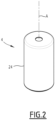
- the cartridge 4 comprises a cartridge body 24 delimiting a cylinder 26 ( Figure 4 ) extending along a central axis A.
- the cylinder 26 preferably has a circular cross-section centered on the central axis A.
- the cylinder 26 can have a rectangular cross-section or any other cross-sectional shape.
- the cylinder 26 designates a cylindrical volume defined in the cartridge body 24.
- the cylinder 26 is delimited by a lateral wall 28 of the cartridge body 24.
- the inner lateral surface is profiled along the central axis A.
- the lateral wall 28 exhibits preferably a circular cross-section centered on the central axis A.
- the cartridge 4 comprises a chamber 30 for storing the vaporizable material 6, the chamber 30 being delimited within the cylinder 26 between a front wall 32 and a piston 34 slidably received in the cylinder 26 such that sliding of the piston forces the vaporizable material 6 out of the chamber 30 via a dispensing opening 32.
- the chamber 30 is filled with the vaporizable material 6.
- the chamber 30 is the section of the cylinder 26 that is located between the front wall 32 and the piston 34.
- the front wall 32 extends across the cylinder 26.
- the front wall 32 is immobile relative to the cartridge body 24.
- the piston 34 is slidable within the cylinder 26. As the piston 34 slides within the cylinder 26 towards the front wall 32, the volume of the chamber 30 diminishes.
- the vaporizable material is a gel with viscosity comprised between 5,000 cps and 50,000 cps.
- the smoking gel could be achieved by increasing its viscosity and a propylene glycol to vegetable glycerin ratio (or "PG/VG ratio") or adding food-grade thickener to the liquid.
- the food-grade thickener can be Xanthan gum.
- the cartridge 4 has advantageously an outer shape that is cylindrical with a circular profile along the central axis A.
- the cartridge 4 is provided with a dispensing opening 38 arranged such that the movement of the piston 34 towards the front wall 32 forces the vaporizable material out of the chamber 30 via the dispensing opening 38.
- the dispensing opening 38 is in fluid communication with the chamber 30.
- the dispensing opening 38 is for example located on the front wall 32, with being preferably centered on the central axis A.
- the piston 34 is movable or operable by an actuator 40 of the aerosol generating device 8.
- the actuator 40 is operable to move the piston 34 within the cylinder 26 towards the front wall 32 of the cartridge 4.
- the actuator 40 comprises for example an axially movable pushing member 42 configured for pushing the piston 34 axially within the cylinder 26 and a drive unit 44 configured for driving the pushing member 36 axially.
- the actuator 40 is preferably powered by the battery 14 and controlled by the controller 16.
- the pushing member 42 and the drive unit 44 cooperate for example via a screw/nut assembly.
- the pushing member 42 comprises for example a threaded rod 46 and the drive unit 44 comprises a nut 46 engaged into the threaded rod 40 and a motor 48 for driving the nut 42 in rotation and thus driving the threaded rod 46 axially to push the piston 34 towards the front wall 32.
- the cartridge 6 optionally comprises a rear wall 50 opposed to the front wall 32.
- the rear wall 50 closes the cylinder 26 at the axial end opposed to front wall 32.
- the cylinder 26 is delimited axially between the front wall 32 and the rear wall 50.
- the rear wall 50 allows reinforcing the cartridge body 24.
- the rear wall 50 is advantageously made in one single piece of material with the lateral wall 28 of the cartridge body 24.
- the rear wall 50 defines an actuator opening 52 configured to receive the pushing member 42 of the actuator 40 of the aerosol generating device 8 to operate the piston 34.
- the actuator opening 52 allows the pushing member 42 to penetrate inside the cartridge 6 to push the piston 34 and to retract outside the cartridge 6, e.g. for removing the cartridge 6 from the aerosol generating device 8.
- the rear wall 50 closing the rear axial end of the cylinder 26 makes the manufacturing of the cartridge 6 easy by inserting the piston 34 inside the cylinder 26 until contact with the rear wall 50 before filling the cartridge 4 with the vaporizable material 6.
- the front wall 32 is formed of a lid 54 that is distinct (or separate) from the cartridge body 24 and attached to the cartridge body in a sealed manner.
- the lid 54 is preferably disc shaped.
- the dispensing opening 38 is preferably provided centrally in the lid 54.
- the lid 54 is preferably glued and/or welded to the cartridge body 24, e.g. by ultrasonic welding.
- the lid 54 separate from the cartridge body 24 allows manufacturing the cartridge 6 easily by inserting the piston 34 inside the cylinder 26, then filling the chamber 30 with the vaporizable material 6 and then closing the front end of the cylinder 26 by attaching the lid 54 to the cartridge body 24.
- the piston 34 is preferably slidable within the cylinder 26 until contact with the front wall 32. This allows maximizing the amount of vaporizable material 6 that can be forced out of the chamber 30, thus increasing the rate of use of the vaporizable material contained in the cartridge 6.
- the provision of the depression 56 and the protrusion 58 allows the remaining amount of the vaporizable material to be pushed into the depression 56 wherein it can be pushed more efficiently outside the cartridge 6 via the dispensing opening 38 located in the depression 56, in particular at a bottom of the depression 56.
- a peripheral edge 34C of the piston 34 is for example in sealing contact with the lateral wall of the cartridge body 24.
- the piston 34 is in interference fit in the cylinder 26. More precisely, the peripheral edge 34C of the piston 34 is interference fit with the lateral wall 28 delimiting the cylinder 26. This improves the sealing between the piston 34 and the cylinder 26.
- the piston 34 comprises advantageously a central region 34D surrounded by a peripheral region 34E ending at the peripheral edge 24C.
- the height of the peripheral edge 34C is preferably smaller than the height of the central region 34D.
- the height is the dimension taken along the central axis A.
- the peripheral region 34E is for example tapering radially outwardly from the central region 34D towards the peripheral edge 34C. This allows providing a robust central region 34D onto which the pushing member 42 of the actuator 40 bear and a thin peripheral edge 34C ensuring a reliable sealing contact with the lateral wall 28 with limited friction.
- the cartridge body 24 is made of a first material and the piston 34 - or at least the peripheral edge 34C of the piston 34 - is made of a second material different from the first material, the second material having a hardness, in particular a shore hardness, higher than that the first material.
- the piston 34 is entirely made in a single piece of the second material (i.e. the piston 34 including the peripheral edge 34C).
- the cartridge 4 comprises a valve 60 configured for selectively closing or opening the dispensing opening 38.
- the valve 60 is advantageously operated by pressure (or "pressure-operated”).
- the pressure-operated valve 60 is configured for staying closed when the pressure inside the chamber 26 is lower than a threshold pressure and for opening when the pressure inside the chamber 26 is higher than said threshold pressure.
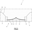
- the valve 60 comprises for example a flexible membrane 62 extending across the dispensing opening 38, the membrane 62 being provided with a valve opening 64, the membrane 62 having a closed configuration in which the valve opening 64 is closed ( Figure 5 ) and an open configuration in which the valve opening 64 is opened ( Figure 6 ).
- the valve opening 64 is for example located in a central region of the membrane 62.
- valve opening 64 allows the vaporizable material 6 contained inside the chamber 30 and pressurized above the threshold pressure under action of the piston 34 to exit the cartridge 4.
- the valve 60 further comprises a sealing material 66 provided on the membrane 62 such as to seal the valve opening 64 in the closed configuration of the valve 60.
- the sealing material 66 is arranged to close the valve opening 64 in a tight manner in the closed configuration of the valve 60 to ensure that the vaporizable material 6 does not leak from the chamber 30.
- the valve 60 comprises for example a layer of sealing material 66 deposited on an outer face of the membrane 62 and/or a layer of sealing material 66 deposited on an inner face of the membrane 62.
- the inner face of the membrane 62 is facing the inside of the chamber 30 and the outer face of the membrane 62 is facing outside the chamber 30.
- the deposition of the sealing material as a layer on an outer face of the membrane 62 or as a layer on inner face of the membrane 62 eases manufacturing of the valve 60 by allowing manufacturing the valve as a multi-layer laminate product.
- the valve 60 comprises a layer of sealing material 66 deposited on the outer face of the membrane 62.
- the valve 60 comprises a layer of sealing material 66 deposited on the inner face of the membrane 62.
- the sealing material 66 is deposited on the membrane 62 as at least one layer, each layer of sealing material 66 covering an entire face of the membrane 62 among the inner face or the outer face of the membrane.
- the membrane 62 of the valve 60 is preferably made as of heat shrinkable material. This allows shaping the valve 60 with a closed configuration favoring tightness and an open configuration easing the flow of the vaporizable product through the valve opening 64. More particularly, the membrane 62 optionally provided with the sealing material 66, in particular with each layer of sealing material 66, is for example provided with the valve opening 64 and then heat shrinked. The heat shrinking of the membrane 62 tends to deform the membrane 62 such as closing the valve opening 64 thus obtaining the closed configuration of the valve.
- the sealing material is preferably not heat shrinkable. This favors the sealing of the valve opening 64 by the sealing material.
- the valve 60 is configured such that in the closed configuration, the central region of the membrane 62 protrudes towards the inside of the chamber 30 relative to a peripheral region of the membrane 62.
- the valve opening 64 is offset axially along the central axis A towards the inside of the chamber 30 relative to the periphery of the membrane 62.
- the center of the membrane 62 preferably points towards the inside of the chamber 30. This ensures a reliable closing of the valve opening 64 in the closed configuration, in particular in conjunction with the sealing material 66.
- the valve 60 is configured such that in the open configuration, the central region of membrane 62 protrudes towards the outside of the chamber 30 relative to the peripheral region of the membrane 62.
- the valve opening 64 is offset axially along the central axis A towards the outside of the chamber 30 relative to the periphery of the membrane 62.
- the center of the membrane 62 preferably points towards the outside of the chamber 30. This ensures a wide opening of the valve opening 64 in the open configuration easing the flow of the vaporizable material 6.
- the valve 60 preferably comprises a mounting frame 68 configured for holding the membrane 62 and for mounting the valve 60 across the dispensing opening 38.
- the mounting frame 68 has for example the shape of a ring configured to be fitted inside the dispensing opening 68.
- the mounting frame 68 may be fixed in the dispensing opening 38 for example by gluing and/or force fitting.
- the peripheral region of the membrane 62 is embedded in the mounting frame 68.
- the mounting frame 68 is for example overmolded on the periphery of the membrane 62.
- the heater 12 is either fixed in the aerosol generating device 8 or preferably replaceable.
- the replaceable heater 12 renders the use of the aerosol generating device 8 more sustainable.
- the aerosol generating device 8 comprises the heater 12 received in a heating cavity 68 arranged to collect the vaporizable material 6 released from the cartridge 4 via the dispensing opening 38.
- the dispensing opening 38 opens into the heating cavity 68 when the cartridge 4 is received the cartridge housing 10.
- the aerosol generating device 8 comprises for example a replaceable heating assembly 70 comprising a heater tray 72 defining the heating cavity 68 and the heater 12 mounted on the heater tray 72 within the heating cavity 68.
- the cartridge 4 comprises provided the cartridge body 24, the piston 34 and the lid 54 provided with the valve 60, then inserting the piston 34 inside the cylinder 26 of the cartridge body 24, then filling the cylinder 26 with vaporizable material 6 and then attaching the lid 54 to the cartridge body 54 thus defining the chamber 30 filled with vaporizable material 6 between the fixed lid 54 and the slidable piston 34.
Landscapes
- Containers And Packaging Bodies Having A Special Means To Remove Contents (AREA)
Priority Applications (1)
| Application Number | Priority Date | Filing Date | Title |
|---|---|---|---|
| EP23168532.2A EP4449916A1 (de) | 2023-04-18 | 2023-04-18 | Kartusche mit kolben und ventil und zugehöriges aerosolerzeugungssystem |
Applications Claiming Priority (1)
| Application Number | Priority Date | Filing Date | Title |
|---|---|---|---|
| EP23168532.2A EP4449916A1 (de) | 2023-04-18 | 2023-04-18 | Kartusche mit kolben und ventil und zugehöriges aerosolerzeugungssystem |
Publications (1)
| Publication Number | Publication Date |
|---|---|
| EP4449916A1 true EP4449916A1 (de) | 2024-10-23 |
Family
ID=86053903
Family Applications (1)
| Application Number | Title | Priority Date | Filing Date |
|---|---|---|---|
| EP23168532.2A Pending EP4449916A1 (de) | 2023-04-18 | 2023-04-18 | Kartusche mit kolben und ventil und zugehöriges aerosolerzeugungssystem |
Country Status (1)
| Country | Link |
|---|---|
| EP (1) | EP4449916A1 (de) |
Citations (4)
| Publication number | Priority date | Publication date | Assignee | Title |
|---|---|---|---|---|
| US9717276B2 (en) * | 2013-10-31 | 2017-08-01 | Rai Strategic Holdings, Inc. | Aerosol delivery device including a positive displacement aerosol delivery mechanism |
| CA3109942A1 (en) * | 2018-08-23 | 2020-02-27 | Gofire Inc. | System and method for vaporizing cartridge system with diffuser |
| US10842953B2 (en) * | 2011-03-09 | 2020-11-24 | Xten Capital Group, Inc. | Medicant delivery system |
| CN216493522U (zh) * | 2021-10-25 | 2022-05-13 | 深圳雾芯科技有限公司 | 液量识别装置以及液量识别系统 |
-
2023
- 2023-04-18 EP EP23168532.2A patent/EP4449916A1/de active Pending
Patent Citations (4)
| Publication number | Priority date | Publication date | Assignee | Title |
|---|---|---|---|---|
| US10842953B2 (en) * | 2011-03-09 | 2020-11-24 | Xten Capital Group, Inc. | Medicant delivery system |
| US9717276B2 (en) * | 2013-10-31 | 2017-08-01 | Rai Strategic Holdings, Inc. | Aerosol delivery device including a positive displacement aerosol delivery mechanism |
| CA3109942A1 (en) * | 2018-08-23 | 2020-02-27 | Gofire Inc. | System and method for vaporizing cartridge system with diffuser |
| CN216493522U (zh) * | 2021-10-25 | 2022-05-13 | 深圳雾芯科技有限公司 | 液量识别装置以及液量识别系统 |
Similar Documents
| Publication | Publication Date | Title |
|---|---|---|
| JP7311085B2 (ja) | 電子エアロゾル供給システム | |
| EP3393559B1 (de) | Aerosolerzeugendes system mit motor | |
| KR102525780B1 (ko) | 피스톤을 포함하는 에어로졸 발생 물품 및 에어로졸 발생 장치 | |
| EP3232836B1 (de) | Aerosolerzeugungssystem mit beweglicher kartusche | |
| MX2010011791A (es) | Dispositivo dispensador de aerosol. | |
| EP4087419B1 (de) | Aerosolerzeugungsvorrichtung mit schalter | |
| EP4069010B1 (de) | Patroneneinsatzsysteme für aerosolerzeugende vorrichtungen | |
| EP4449916A1 (de) | Kartusche mit kolben und ventil und zugehöriges aerosolerzeugungssystem | |
| KR102760374B1 (ko) | 전자 흡연 디바이스, 지급기, 흡연 시스템 및 담배 무스 제제를 공급하는 방법 | |
| EP4398752B1 (de) | Aerosolerzeugungspatrone und -system mit nikotingel | |
| EP4573940A1 (de) | Aerosolerzeugungskartusche für eine aerosolerzeugungsvorrichtung und zugehörige aerosolerzeugungsvorrichtung | |
| US20250204595A1 (en) | An Aerosol Generating Device, and Associated Aerosol Generating System | |
| EP4140333A1 (de) | Kartusche mit beschichtung zum lagern eines verdampfbaren materials | |
| KR102548517B1 (ko) | 에어로졸 생성 장치 | |
| JP7658970B2 (ja) | カートリッジを穿孔するように構成されたシーシャ装置 | |
| KR20220110483A (ko) | 카트리지 방출 시스템을 갖는 에어로졸 발생 장치 | |
| KR20220109388A (ko) | 관통 조립체를 갖춘 에어로졸 발생 장치 | |
| US20240349811A1 (en) | Aerosol Delivering System Comprising a Priming Bulb, and Cartridge and Aerosol Generating Device Comprising Such an Aerosol Delivering System | |
| CN223298561U (zh) | 雾化器和气溶胶生成装置 | |
| WO2024056819A1 (en) | Cartridge comprising a wick forming airflow channels and associated aerosol generating system | |
| EA040716B1 (ru) | Электронное курительное устройство, дозирующее устройство, курительная система и способ подачи состава табачного мусса |
Legal Events
| Date | Code | Title | Description |
|---|---|---|---|
| PUAI | Public reference made under article 153(3) epc to a published international application that has entered the european phase |
Free format text: ORIGINAL CODE: 0009012 |
|
| STAA | Information on the status of an ep patent application or granted ep patent |
Free format text: STATUS: THE APPLICATION HAS BEEN PUBLISHED |
|
| AK | Designated contracting states |
Kind code of ref document: A1 Designated state(s): AL AT BE BG CH CY CZ DE DK EE ES FI FR GB GR HR HU IE IS IT LI LT LU LV MC ME MK MT NL NO PL PT RO RS SE SI SK SM TR |
|
| STAA | Information on the status of an ep patent application or granted ep patent |
Free format text: STATUS: REQUEST FOR EXAMINATION WAS MADE |
|
| 17P | Request for examination filed |
Effective date: 20250324 |