EP4450104A1 - Détermination d'une concentration de gaz dans un système respiratoire - Google Patents
Détermination d'une concentration de gaz dans un système respiratoire Download PDFInfo
- Publication number
- EP4450104A1 EP4450104A1 EP24167362.3A EP24167362A EP4450104A1 EP 4450104 A1 EP4450104 A1 EP 4450104A1 EP 24167362 A EP24167362 A EP 24167362A EP 4450104 A1 EP4450104 A1 EP 4450104A1
- Authority
- EP
- European Patent Office
- Prior art keywords
- gas
- line
- signal
- main line
- gas concentration
- Prior art date
- Legal status (The legal status is an assumption and is not a legal conclusion. Google has not performed a legal analysis and makes no representation as to the accuracy of the status listed.)
- Granted
Links
Images

Classifications
-
- A—HUMAN NECESSITIES
- A61—MEDICAL OR VETERINARY SCIENCE; HYGIENE
- A61M—DEVICES FOR INTRODUCING MEDIA INTO, OR ONTO, THE BODY; DEVICES FOR TRANSDUCING BODY MEDIA OR FOR TAKING MEDIA FROM THE BODY; DEVICES FOR PRODUCING OR ENDING SLEEP OR STUPOR
- A61M16/00—Devices for influencing the respiratory system of patients by gas treatment, e.g. ventilators; Tracheal tubes
- A61M16/10—Preparation of respiratory gases or vapours
- A61M16/1005—Preparation of respiratory gases or vapours with O2 features or with parameter measurement
-
- A—HUMAN NECESSITIES
- A61—MEDICAL OR VETERINARY SCIENCE; HYGIENE
- A61M—DEVICES FOR INTRODUCING MEDIA INTO, OR ONTO, THE BODY; DEVICES FOR TRANSDUCING BODY MEDIA OR FOR TAKING MEDIA FROM THE BODY; DEVICES FOR PRODUCING OR ENDING SLEEP OR STUPOR
- A61M16/00—Devices for influencing the respiratory system of patients by gas treatment, e.g. ventilators; Tracheal tubes
- A61M16/021—Devices for influencing the respiratory system of patients by gas treatment, e.g. ventilators; Tracheal tubes operated by electrical means
- A61M16/022—Control means therefor
- A61M16/024—Control means therefor including calculation means, e.g. using a processor
-
- A—HUMAN NECESSITIES
- A61—MEDICAL OR VETERINARY SCIENCE; HYGIENE
- A61M—DEVICES FOR INTRODUCING MEDIA INTO, OR ONTO, THE BODY; DEVICES FOR TRANSDUCING BODY MEDIA OR FOR TAKING MEDIA FROM THE BODY; DEVICES FOR PRODUCING OR ENDING SLEEP OR STUPOR
- A61M16/00—Devices for influencing the respiratory system of patients by gas treatment, e.g. ventilators; Tracheal tubes
- A61M16/0003—Accessories therefor, e.g. sensors, vibrators, negative pressure
-
- A—HUMAN NECESSITIES
- A61—MEDICAL OR VETERINARY SCIENCE; HYGIENE
- A61M—DEVICES FOR INTRODUCING MEDIA INTO, OR ONTO, THE BODY; DEVICES FOR TRANSDUCING BODY MEDIA OR FOR TAKING MEDIA FROM THE BODY; DEVICES FOR PRODUCING OR ENDING SLEEP OR STUPOR
- A61M16/00—Devices for influencing the respiratory system of patients by gas treatment, e.g. ventilators; Tracheal tubes
- A61M16/021—Devices for influencing the respiratory system of patients by gas treatment, e.g. ventilators; Tracheal tubes operated by electrical means
- A61M16/022—Control means therefor
- A61M16/024—Control means therefor including calculation means, e.g. using a processor
- A61M16/026—Control means therefor including calculation means, e.g. using a processor specially adapted for predicting, e.g. for determining an information representative of a flow limitation during a ventilation cycle by using a root square technique or a regression analysis
-
- A—HUMAN NECESSITIES
- A61—MEDICAL OR VETERINARY SCIENCE; HYGIENE
- A61M—DEVICES FOR INTRODUCING MEDIA INTO, OR ONTO, THE BODY; DEVICES FOR TRANSDUCING BODY MEDIA OR FOR TAKING MEDIA FROM THE BODY; DEVICES FOR PRODUCING OR ENDING SLEEP OR STUPOR
- A61M16/00—Devices for influencing the respiratory system of patients by gas treatment, e.g. ventilators; Tracheal tubes
- A61M16/08—Bellows; Connecting tubes ; Water traps; Patient circuits
- A61M16/0816—Joints or connectors
- A61M16/0841—Joints or connectors for sampling
- A61M16/085—Gas sampling
-
- A—HUMAN NECESSITIES
- A61—MEDICAL OR VETERINARY SCIENCE; HYGIENE
- A61M—DEVICES FOR INTRODUCING MEDIA INTO, OR ONTO, THE BODY; DEVICES FOR TRANSDUCING BODY MEDIA OR FOR TAKING MEDIA FROM THE BODY; DEVICES FOR PRODUCING OR ENDING SLEEP OR STUPOR
- A61M16/00—Devices for influencing the respiratory system of patients by gas treatment, e.g. ventilators; Tracheal tubes
- A61M16/08—Bellows; Connecting tubes ; Water traps; Patient circuits
- A61M16/0883—Circuit type
- A61M16/0891—Closed circuit, e.g. for anaesthesia
-
- A—HUMAN NECESSITIES
- A61—MEDICAL OR VETERINARY SCIENCE; HYGIENE
- A61M—DEVICES FOR INTRODUCING MEDIA INTO, OR ONTO, THE BODY; DEVICES FOR TRANSDUCING BODY MEDIA OR FOR TAKING MEDIA FROM THE BODY; DEVICES FOR PRODUCING OR ENDING SLEEP OR STUPOR
- A61M16/00—Devices for influencing the respiratory system of patients by gas treatment, e.g. ventilators; Tracheal tubes
- A61M16/0003—Accessories therefor, e.g. sensors, vibrators, negative pressure
- A61M2016/0027—Accessories therefor, e.g. sensors, vibrators, negative pressure pressure meter
-
- A—HUMAN NECESSITIES
- A61—MEDICAL OR VETERINARY SCIENCE; HYGIENE
- A61M—DEVICES FOR INTRODUCING MEDIA INTO, OR ONTO, THE BODY; DEVICES FOR TRANSDUCING BODY MEDIA OR FOR TAKING MEDIA FROM THE BODY; DEVICES FOR PRODUCING OR ENDING SLEEP OR STUPOR
- A61M16/00—Devices for influencing the respiratory system of patients by gas treatment, e.g. ventilators; Tracheal tubes
- A61M16/10—Preparation of respiratory gases or vapours
- A61M16/1005—Preparation of respiratory gases or vapours with O2 features or with parameter measurement
- A61M2016/102—Measuring a parameter of the content of the delivered gas
- A61M2016/103—Measuring a parameter of the content of the delivered gas the CO2 concentration
-
- A—HUMAN NECESSITIES
- A61—MEDICAL OR VETERINARY SCIENCE; HYGIENE
- A61M—DEVICES FOR INTRODUCING MEDIA INTO, OR ONTO, THE BODY; DEVICES FOR TRANSDUCING BODY MEDIA OR FOR TAKING MEDIA FROM THE BODY; DEVICES FOR PRODUCING OR ENDING SLEEP OR STUPOR
- A61M2206/00—Characteristics of a physical parameter; associated device therefor
- A61M2206/10—Flow characteristics
Definitions
- the invention relates to a method for determining a gas concentration in a ventilation system. Furthermore, the invention relates to a signal processing device, a computer program and a computer-readable medium for carrying out the method, as well as a ventilation system.
- the concentration of carbon dioxide in a respiratory gas flowing in a ventilation system can be determined by a mainstream measurement or a sidestream measurement.
- the concentration is measured directly using a gas sensor arranged in the airway, i.e. in the main flow of the respiratory gas.
- a gas sensor arranged in the airway, i.e. in the main flow of the respiratory gas.
- the gas sensor requires a certain minimum volume to produce accurate measurement results, which can lead to unwanted rebreathing of carbon dioxide, particularly when ventilating newborns or infants.
- Such a gas sensor can also be uncomfortable for the patient due to its size and weight.
- part of the respiratory gas is diverted at the respective sampling point, for example a nasal cannula or a mask, and fed to an external gas sensor, which can be arranged in the ventilator.
- Such a sidestream measurement is usually less accurate than the mainstream measurement.
- One object of the invention can be seen in creating a method that enables a gas concentration in a ventilation system to be determined as accurately as possible and avoids the aforementioned disadvantages of a conventional mainstream measurement.
- a further object of the invention can be seen in providing a signal processing device, a computer program and a computer-readable medium for carrying out such a method, as well as a corresponding ventilation system.
- a first aspect of the invention relates to a method for determining a gas concentration in a ventilation system.
- the ventilation system comprises: a ventilator with a connection for providing a breathing gas; a main line for connecting the connection to a patient interface; a secondary line branching off from the main line so that the breathing gas can flow at least partially through the secondary line; a gas sensor for measuring a gas concentration at at least a first location in the secondary line; a signal processing device.
- the method comprises the following steps: receiving a first signal indicative of the gas concentration measured by the gas sensor in the signal processing device; generating a second signal indicative of an estimated gas concentration at at least one second location in the main line that differs from the first location from the first signal by the signal processing device.
- the gas concentration at a specific location in the bypass line i.e. in the bypass flow
- the gas concentration at another location in the main line i.e. in the main flow
- the gas concentration at another location in the main line can then be estimated, for example using a mathematical model of the gas sensor and a known volume flow of the breathing gas in the main line and/or the bypass line (see below).
- Such an estimate can achieve a similar accuracy to a conventional mainstream measurement without the need to integrate the gas sensor into the main line. This reduces the overall volume of the main line. This can reduce the likelihood of unwanted rebreathing of exhaled gas. It also reduces the overall weight of the main line. This can improve patient comfort, especially when ventilating neonates or infants.
- the method can be computer-implemented.
- signal as in “first signal”, “second signal” or “third signal” (see below) can mean an analog or digital signal.
- a second aspect of the invention relates to a signal processing device comprising means for carrying out the method described above and below.
- the means can comprise hardware and/or software modules.
- the means can comprise a processor that is configured to carry out the (computer-implemented) method.
- the means can comprise a memory and/or a data communication interface for wireless and/or wired data communication with peripheral devices.
- the signal processing device can be implemented exclusively as hardware, for example in the form of an ASIC or FPGA module.
- a third aspect of the invention relates to a ventilation system.
- the ventilation system comprises: a ventilator with a connection for providing a breathing gas; a main line for connecting the connection to a patient interface; a secondary line that branches off from the main line so that the breathing gas can flow at least partially through the secondary line; a gas sensor for measuring a gas concentration at at least a first location in the secondary line; a signal processing device as described above and below.
- ventilator can be understood to mean, for example, a home ventilator, a sleep therapy device, an intensive care ventilator, an anesthesia device or a combination of at least two of these examples.
- the ventilator can be designed for invasive and/or non-invasive ventilation.
- a "line” as in “main line” or “secondary line” can mean a (flexible) hose.
- rigid lines are also possible.
- the breathing gas flowing through the main line can also be referred to as the mainstream.
- the breathing gas flowing through the secondary line can also be referred to as the secondary stream.
- patient interface can be understood as, for example, an intubation tube, a nasal cannula or a breathing mask.
- the secondary line may differ significantly from the main line in its total volume and/or total length.
- a “gas sensor” can be understood as an infrared optical sensor, also known as a non-dispersive infrared sensor or NDIR sensor for short, or a metal oxide semiconductor sensor, known as an MOX sensor for short. It is also possible to use a gas sensor that measures the gas concentration based on the thermal conductivity of the respective gas or gas mixture, also known as a thermal conductivity detector, or paramagnetically.
- the gas sensor can be arranged at least partially, for example with its active surface, in the secondary line in order to measure the gas concentration directly in the secondary line.
- the computer program comprises instructions which cause a processor (for example a processor of the signal processing device described above and below) to carry out the method described above and below when the computer program is executed by the processor.
- a processor for example a processor of the signal processing device described above and below
- the computer-readable medium may be a volatile or non-volatile data storage device.
- the computer-readable medium may be a hard disk, a universal serial bus (USB) storage device , a random-access memory (RAM) , a read-only memory (ROM) , an erasable programmable read-only memory (EPROM), an electrically erasable programmable read-only memory (EEPROM), a flash memory, or a combination of two or more of these examples.
- the computer-readable medium may also be a data communications network that enables downloading of program code (e.g., over the Internet), or a cloud.
- the estimated gas concentration can be determined depending on a time derivative of the measured gas concentration.
- at least a part of the second signal can correspond to or be based on a time derivative of the first signal.
- the gas concentration at the second location or locations can be estimated with sufficient accuracy.
- Such an estimate also has the advantage that it can be implemented very easily as hardware and/or software.
- ConcSensor stands for the measured gas concentration
- ConcAirway for the estimated gas concentration
- ⁇ for a constant, for example a time constant.
- the second signal is generated from the first signal using a first-order (inverse) filter.
- the equation can be transformed, for example, by Laplace transformation and/or discretized, i.e. digitized, in order to generate the second signal, i.e. to calculate values for the estimated gas concentration.
- the equation can be stored, for example, as a mathematical function or lookup table in a memory of the signal processing device.
- the at least one second location can comprise a branching location at which the secondary line branches off from the main line.
- the branching location can, for example, be a location at which the gas concentration would be measured (instead of estimated as here) in a conventional main flow measurement.
- the first signal can be evaluated to estimate the gas concentration at least at the branching location. This enables, for example, a very precise determination of the amount of exhaled carbon dioxide.
- the second signal may be generated using a mathematical model of the gas sensor.
- the mathematical model may, for example, comprise a system of differential equations for defining a relationship between the first and the second signal.
- the mathematical model can be defined by certain parameters that describe physical and/or chemical properties of the gas sensor.
- the mathematical model can be used to approximately simulate a signal from the gas sensor that the gas sensor would generate if it measured the gas concentration at the second location or locations instead of at the first location or locations.
- the mathematical model can, for example, be defined by at least one of the following parameters: one or more time constants, a volume of the main and/or secondary line, a volume flow of the breathing gas in the main and/or secondary line, a dead volume.
- the time constant can, for example, be a quotient of the volume and the volume flow.
- the mathematical model can, for example, have been determined by analyzing a step response resulting from a sudden change in the gas concentration at the second location or locations.
- the second signal can be generated depending on a known measuring volume of the gas sensor.
- the "measuring volume” can be understood as the volume of a measuring chamber of the gas sensor through which the breathing gas flows.
- the known measuring volume can, for example, be a parameter of the mathematical model of the gas sensor.
- the second signal can be generated depending on a known volume flow of the breathing gas in the main line.
- the second signal can be generated depending on a known volume flow of the breathing gas in the secondary line.
- a known volume flow can be, for example, a measured volume flow and/or be predetermined by the known properties of the main line and/or the secondary line.
- the known volume flow of the breathing gas in the main line and/or the secondary line can, for example, be a parameter of the mathematical model of the gas sensor.
- the known volume flow of the breathing gas in the secondary line can have either a constant amount or a constant direction or both a constant amount and a constant direction, regardless of a (known or unknown) pressure (and/or volume flow) of the breathing gas in the main line.
- the volume flow in the The secondary line can be controlled so that it remains more or less the same, even if the pressure (and/or the volume flow) in the main line or in a section of the main line changes significantly, for example during the transition between inspiration and expiration.
- the known volume flow of the breathing gas in the bypass line can be 2 ml/s or less, in particular 1 ml/s or less. Such values are particularly favorable for the ventilation of newborns or infants.
- ⁇ VolumeSensor / Flow .
- VolumeSensor stands for the known measuring volume of the gas sensor
- Flow stands for the known volume flow of the breathing gas in the bypass line.
- d d t ConcSensor flow / VolumeSensor ⁇ ConcAirway ⁇ ConcSensor .
- the measured gas concentration may be a carbon dioxide concentration.
- the estimated gas concentration may be a carbon dioxide concentration.
- the method may further comprise a step of filtering the second signal in order to smooth the second signal.
- suitable filters are bandpass, highpass or lowpass filters.
- other filters are also possible. In this way, for example, unwanted noise in the second signal can be suppressed. The accuracy in determining the gas concentration can thus be further improved.
- the second signal can be filtered with a low-pass filter. This allows unwanted noise in the second signal to be suppressed particularly effectively using simple means.
- a third signal indicating a pressure difference measured by a pressure sensor between different points of the main line can also be received in the signal processing device.
- the second signal can then be generated with additional use of the third signal.
- the third signal can be used, for example, to determine a volume flow of the respiratory gas in the main line and/or the secondary line and/or a ventilation pressure and/or to control a pump of the ventilation system (see below) so that a volume flow of the respiratory gas in the main line and/or the secondary line approaches a certain target value.
- the target value can be, for example, 2 ml/s or less, in particular 1 ml/s or less.
- the ventilation system can further comprise a respiratory gas filter for filtering the respiratory gas before it enters the gas sensor. This can prevent measurement errors due to contamination and/or damage to the gas sensor.
- the breathing gas filter can comprise either a water trap or a particle filter or both a water trap and a particle filter.
- particle filter can be understood above and below to mean in particular a hydrophobic particle filter which can additionally remove moisture from the breathing gas.
- the ventilation system in particular the secondary line, can be designed such that a volume flow of the respiratory gas in the secondary line has either a constant amount or a constant direction or both a constant amount and a constant direction, regardless of a pressure (and/or a volume flow) of the respiratory gas in the main line. This can ensure that the measurement of the gas concentration takes place at different times under approximately the same measuring conditions.
- the ventilation system in particular the secondary line, can be designed such that a volume flow of the respiratory gas in the secondary line is 2 ml/s or less, in particular 1 ml/s or less. Such values are particularly favorable for the ventilation of newborns or infants.
- the secondary line can comprise a diaphragm for adjusting the volume flow of the breathing gas in the secondary line.
- the term "diaphragm" can be understood as a specially shaped, in particular abrupt local narrowing of the cross-section of the secondary line, for example in the form of a disk or a perforated grid, the local narrowing forming a flow resistance.
- the diaphragm For example, it can have an opening with a diameter that varies in the direction of flow. Very good results have been achieved in tests with such an orifice. Alternatively, a throttle or a control valve can also be used.
- the secondary line can comprise a first line section and a second line section.
- the gas sensor can be arranged in the first line section and the second line section can bypass the gas sensor.
- Such a bypass makes it possible to maintain the volume flow of the breathing gas through the secondary line even if the path via the gas sensor is blocked or narrowed for some reason.
- the first line section can comprise a first aperture for adjusting a volume flow of the breathing gas in the first line section. In this way, the volume flow in the first line section can be adjusted to a specific value with little design effort.
- the second line section can comprise a second aperture for adjusting a volume flow of the breathing gas in the second line section. In this way, the volume flow in the second line section can be adjusted to a specific value with little design effort.
- the combination of the two orifices ensures that the volume flow of the breathing gas - especially where it enters the gas sensor - approaches a certain target value.
- the second orifice can have a smaller opening than the first orifice. This has the effect that a sufficiently strong volume flow is generated in the second line section if the first line section is blocked for any reason, in particular if a breathing gas filter upstream of the gas sensor in the first line section (hereinafter also referred to as the first breathing gas filter) is blocked, so that the blocked breathing gas filter can be flushed accordingly and made permeable again.
- the first aperture can be arranged between an outlet opening of the gas sensor and a mouth point at which the second line section opens into the first line section.
- the first line section can comprise a first respiratory gas filter.
- the first respiratory gas filter can comprise, for example, a particle filter and/or a water trap.
- the first respiratory gas filter can be arranged such that it is flushed by the volume flow of the respiratory gas in the second line section. In this way, for example, mucus or moisture can be removed from the first respiratory gas filter via the second line section. Blockages in the first respiratory gas filter can thus be avoided or eliminated.
- the second line section can comprise a second breathing gas filter.
- the second breathing gas filter can comprise, for example, a particle filter and/or a water trap.
- the first and second breathing gas filters can be of the same type or of different types.
- an outlet of the first breathing gas filter can be connected to an inlet opening of the gas sensor. Additionally or alternatively, the outlet can be connected to an inlet of the second breathing gas filter.
- the first breathing gas filter can be connected to the gas sensor in such a way that the gas sensor can measure the gas concentration in the breathing gas filtered by the first breathing gas filter.
- the first and second breathing gas filters can be connected in series with each other and/or with at least one third breathing gas filter in order to enable two- or multi-stage filtering of the breathing gas.
- the outlet of the first breathing gas filter can be connected to the inlet of the second breathing gas filter via at least one third breathing gas filter.
- at least three breathing gas filters can be connected in series to filter the breathing gas.
- Each breathing gas filter can, for example, comprise a particle filter and/or a water trap.
- the first breathing gas filter can comprise a first particle filter
- the second breathing gas filter can comprise a second particle filter
- the at least one third breathing gas filter can comprise a water trap. This enables particularly thorough filtering of the breathing gas.
- the ventilation system can comprise a pump arranged in the main or secondary line for conveying the breathing gas.
- at least one first pump can be arranged in the main line and at least one second pump in the secondary line.
- the pump can also be arranged in the ventilator instead.
- the pump can, for example, be designed to generate a negative pressure in the main and/or secondary line.
- the negative pressure can deviate from the ambient pressure by a factor of between 0.4 and 0.6, in particular between 0.50 and 0.55.
- the pump can be controlled using the first signal, the second signal or the third signal or using at least two of these signals.
- the third signal can be used to detect a blockage or other undesirable cross-sectional narrowing of the main line.
- the pump can be controlled in such a way that no negative pressure is created in the alveoli of the ventilated patient, in particular a newborn or infant.
- the pump can be deactivated if the measured pressure in the main line exceeds a certain threshold, for example falls below 2 mbar.
- the third signal can be used to determine a current (positive or negative) value of a ventilation pressure, which can be used, for example, to control the pump so that the current value approaches a certain target value.
- the pump can be arranged in the first line section and the second line section between the pump and the gas sensor can open into the first line section.
- the ventilation system can comprise a suction device arranged in the main or secondary line for suctioning liquid, in particular secretion or mucus. In this way, blockages can be avoided.
- the suction device can be arranged in the main line between a branch point at which the secondary line branches off from the main line and the patient interface. In this way, it can be avoided that liquid, in particular secretion or mucus, penetrates into the main and secondary lines when exhaling.
- the suction device can be installed in the main line between the ventilator connection and a branch point where the branch line branches off from the main line. branches off.
- the suction device can be arranged between a point at which a pressure sensor is connected to the main line and the branch point.
- the ventilation system can comprise a pressure sensor for measuring a pressure difference between different points of the main line.
- the pressure sensor can, for example, be connected to the signal processing device for data communication.
- the ventilation system may comprise an additional pressure sensor for measuring a ventilation pressure with which the patient is currently being ventilated, for example at the branch point or at another location as close as possible to the patient interface.
- a first pressure port of the pressure sensor can be connected to the main line between the connection of the ventilator and a branch point at which the secondary line branches off from the main line.
- a second pressure port of the pressure sensor can be connected to the main line between a point at which the first pressure port is connected to the main line and the patient interface.
- the second pressure connection can be connected to the main line between the connection of the ventilator and the branch point.
- the second pressure connection can be connected to the main line at the branch point.
- the secondary line can have an opening through which the breathing gas can flow into the environment.
- the opening can be formed by a free, open end of the secondary line, so that the breathing gas can flow into the environment after it has passed the gas sensor.
- the ventilator can comprise a further connection for connecting the secondary line, so that the breathing gas can flow from the secondary line back into the ventilator. More precisely, the breathing gas can flow back into the ventilator via the further connection after it has passed the gas sensor.
- the ventilator can thus feed the returned breathing gas back to the ventilator, for example after appropriate processing in the ventilator. the port connected to the main line. This can improve the efficiency of the ventilation system.
- the ventilation system can be designed for ventilating newborns and/or infants.
- Fig. 1 shows a ventilation system 1, which comprises a ventilator 3 with a connection 5a for providing a breathing gas, a main line 7 and a secondary line 9.
- the main line 7 connects the connection 5a to a patient interface 11, for example an intubation tube, a nasal cannula or a breathing mask.
- the secondary line 9 branches off from the main line 7 at a branch point 13, so that the breathing gas can flow during ventilation not only between the connection 5a and the patient interface 11, but also partially through the secondary line 9. Possible flow directions of the breathing gas are shown in Fig. 1 marked with solid arrows.
- the ventilation system 1 further comprises a gas sensor 15 for measuring a gas concentration at at least one first location 17 in the secondary line 9.
- the gas sensor 15, for example a carbon dioxide sensor, can be arranged at least partially in the secondary line 9.
- the gas sensor 15 is designed to generate a first signal 19 which indicates the gas concentration measured at the first location 17 or the first locations 17.
- the gas sensor 15 is connected to a signal processing device 21 of the ventilation system 1 for data communication.
- the Signal processing device 21 can, as shown here, be a component of the ventilator 3.
- the signal processing device 21 is designed to carry out a method for determining a gas concentration in the ventilation system 1.
- the signal processing device 21 can comprise, for example, a memory and a processor (not shown).
- a computer program can be stored in the memory and the processor can be configured to carry out the method by executing the computer program.
- the method comprises a first step in which the first signal 19 is received in the signal processing device 21 via a suitable data communication connection, which can be wired or wireless.
- the signal processing device 21 In a second step, the signal processing device 21 generates a second signal 23 from the first signal 19, which indicates an estimated gas concentration at at least one second location 25 in the main line 7 that differs from the first location 17.
- the second location 25 corresponds to the branch point 13.
- the second location 25 can also be another location on the main line 7.
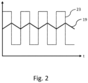
- the signal processing device 21 generates the second signal 23 depending on a time derivative of the first signal 19, as shown by way of example in Fig. 2
- the signals 19, 23 are in Fig. 2 shown in idealized form. In reality, the signals 19, 23 may have a slightly different form, for example, they may be more or less noisy.
- the second signal 23 may be generated using a mathematical model of the gas sensor 15.
- ConcSensor stands for the gas concentration measured at the first position 17 or the first 17 positions
- Flow for a known volume flow of the breathing gas in the secondary line 9
- VolumeSensor for a known measuring volume of the gas sensor 15
- ConcAirway for the estimated gas concentration
- the ventilation system 1, in particular the main line 7 and/or the secondary line 9, can be designed such that the volume flow in the secondary line 9 is approximately constant, i.e. has the same amount and the same direction, even if the pressure in the main line 7 changes, for example during the transition between inhalation and exhalation.
- the volume flow in the secondary line 9 is 2 ml/s or less or even 1 ml/s or less.
- the second signal 23 can be smoothed by the signal processing device 21, for example using a low-pass filter, to suppress unwanted noise.
- a third signal 29 provided by a pressure sensor 27 is taken into account, wherein the third signal 29 indicates a pressure difference between different locations of the main line 7.
- the third signal 29 indicates a pressure difference between different locations of the main line 7.
- at least one of the following variables can be determined based on the (measured) pressure difference: a current volume flow between the connection 5a and the branch point 13, a current volume flow between the branch point 13 and the patient interface 11, a current volume flow in the secondary line 7, a current ventilation pressure in the main line 7, in particular at the branch point 13.
- the gas concentration in this case the carbon dioxide concentration
- the main line 7 is made lighter by arranging the gas sensor 15 in the secondary line 9, which makes handling easier and improves comfort for the patient.
- the secondary line 9 comprises a first line section 9a and a second line section 9b, wherein the gas sensor 15 in the first line section 9a and the second line section 9b bridges the gas sensor 15 arranged in the first line section 9a.
- a first breathing gas filter 31a for example in the form of a first particle filter, can be arranged in the first line section 9a, so that the breathing gas is filtered before it enters the gas sensor 15.
- a second breathing gas filter 31b for example in the form of a second particle filter, can be arranged in the second line section 9b, so that the breathing gas is filtered before it leaves the second line section 9b.
- At least a third breathing gas filter 31c is arranged between the breathing gas filters 31a, 31b, for example in the form of a water trap in the second line section 9b. This has the effect that the breathing gas exiting the first breathing gas filter 31a is additionally filtered before it enters the second breathing gas filter 31b.
- the secondary line 9 can have one or more orifices.
- a first aperture 35a is arranged between an outlet opening of the gas sensor 15, through which the breathing gas exits the gas sensor 15, and a mouth point 33, at which the second line section 9b opens into the first line section 9a, which adjusts the volume flow in the first line section 9a.
- a second aperture 35b can be arranged in the second line section 9b, for example between the mouth 33 and an outlet of the second breathing gas filter 31b, which adjusts the volume flow in the second line section 9b.
- the first orifice 35a only adjusts a part of the volume flow in the first line section 9a.
- the other part is adjusted by the second orifice 35b.
- the (total) volume flow through the first line section 9a thus corresponds to a sum of the volume flow through the first orifice 35a and the volume flow through the second orifice 35b.
- the orifices 35a, 35b can be designed such that the total volume flow in the secondary line 9, in particular the volume flow between the branch point 13 and the inlet opening of the gas sensor is 15.2 ml/s or less or even 1 ml/s or less.
- a suitable pump 37 can be arranged in the secondary line 9, for example in the first line section 9a between the outlet point 33 and one end of the secondary line 9.
- the pump 37 can alternatively be arranged in the main line 7 or in the ventilator 3.
- the end of the secondary line 9 can be open so that the breathing gas can flow into the environment, as in Fig. 1 indicated by a dashed line.
- the end of the secondary line 9 can be connected to another connection 5b of the ventilator 3, so that the breathing gas can flow from the secondary line 9 back into the ventilator 3 in order to be fed from there back into the main line 7, for example after suitable processing in the ventilator 3.
- the ventilation system 1 can comprise a suitable suction device 39 for sucking out and collecting such liquids.
- the suction device 39 is arranged in the main line 7 between the branch point 13 and the patient interface 11. In this way, blockages of the pressure sensor 27 can be avoided, among other things.
- first pressure connection 41a of the pressure sensor 27 is connected to the main line 7 between the suction device 39 and the branch point 13 and a second pressure connection 41b of the pressure sensor 27 is connected to the main line 7 between the branch point 13 and the patient interface 11.
- a configuration is also possible in which both pressure connections 41a, 41b are connected to the main line 7 between the connection 5a and the branch point 13.
Landscapes
- Health & Medical Sciences (AREA)
- Emergency Medicine (AREA)
- Pulmonology (AREA)
- Engineering & Computer Science (AREA)
- Anesthesiology (AREA)
- Biomedical Technology (AREA)
- Heart & Thoracic Surgery (AREA)
- Hematology (AREA)
- Life Sciences & Earth Sciences (AREA)
- Animal Behavior & Ethology (AREA)
- General Health & Medical Sciences (AREA)
- Public Health (AREA)
- Veterinary Medicine (AREA)
- Measurement Of The Respiration, Hearing Ability, Form, And Blood Characteristics Of Living Organisms (AREA)
Applications Claiming Priority (1)
| Application Number | Priority Date | Filing Date | Title |
|---|---|---|---|
| DE102023109772 | 2023-04-18 |
Publications (2)
| Publication Number | Publication Date |
|---|---|
| EP4450104A1 true EP4450104A1 (fr) | 2024-10-23 |
| EP4450104B1 EP4450104B1 (fr) | 2025-11-12 |
Family
ID=90544656
Family Applications (1)
| Application Number | Title | Priority Date | Filing Date |
|---|---|---|---|
| EP24167362.3A Active EP4450104B1 (fr) | 2023-04-18 | 2024-03-28 | Détermination d'une concentration de gaz dans un système respiratoire |
Country Status (3)
| Country | Link |
|---|---|
| US (1) | US20240350756A1 (fr) |
| EP (1) | EP4450104B1 (fr) |
| DE (1) | DE102024108862A1 (fr) |
Citations (4)
| Publication number | Priority date | Publication date | Assignee | Title |
|---|---|---|---|---|
| US5081871A (en) * | 1989-02-02 | 1992-01-21 | The United States Of America As Represented By The Secretary Of The Department Of Health And Human Services | Breath sampler |
| US6000397A (en) * | 1996-07-29 | 1999-12-14 | Siemens Elema Ab | Method and device for detecting a variation in a flowing medium |
| US20110004108A1 (en) * | 2007-11-16 | 2011-01-06 | Philip John Peyton | System and method for monitoring cardiac output |
| US20210109084A1 (en) * | 2019-10-15 | 2021-04-15 | GE Precision Healthcare LLC | Respiratory Gas Sensor System with Color Detection |
-
2024
- 2024-03-27 DE DE102024108862.1A patent/DE102024108862A1/de active Pending
- 2024-03-28 EP EP24167362.3A patent/EP4450104B1/fr active Active
- 2024-04-02 US US18/624,291 patent/US20240350756A1/en active Pending
Patent Citations (4)
| Publication number | Priority date | Publication date | Assignee | Title |
|---|---|---|---|---|
| US5081871A (en) * | 1989-02-02 | 1992-01-21 | The United States Of America As Represented By The Secretary Of The Department Of Health And Human Services | Breath sampler |
| US6000397A (en) * | 1996-07-29 | 1999-12-14 | Siemens Elema Ab | Method and device for detecting a variation in a flowing medium |
| US20110004108A1 (en) * | 2007-11-16 | 2011-01-06 | Philip John Peyton | System and method for monitoring cardiac output |
| US20210109084A1 (en) * | 2019-10-15 | 2021-04-15 | GE Precision Healthcare LLC | Respiratory Gas Sensor System with Color Detection |
Also Published As
| Publication number | Publication date |
|---|---|
| US20240350756A1 (en) | 2024-10-24 |
| DE102024108862A1 (de) | 2024-10-24 |
| EP4450104B1 (fr) | 2025-11-12 |
Similar Documents
| Publication | Publication Date | Title |
|---|---|---|
| EP0891199B1 (fr) | Dispositif et procede pour surveiller des parametres de respiration d'un systeme de respiration artificielle | |
| EP1148907B1 (fr) | Procede non invasif pour l'optimisation de la respiration de poumons atelectasiques | |
| DE60016284T2 (de) | Nichtinvasive bestimmung von herzzeitvolumen, pulmonalem blutfluss und blutgasgehalt | |
| DE60204336T2 (de) | Atemfunktionsanalyse mittels kapnographie | |
| DE69020615T2 (de) | Verfahren und Gerät zur Überwachung des Stoffwechsels. | |
| DE102007038856A1 (de) | Nicht-Invasive Bestimmung des vom Herzen geförderten Blutvolumens, des Gasaustausches und der Gaskonzentration des arteriellen Blutes | |
| DE102008027630A1 (de) | Transportabler Pneumotachograph zur Messung von Bestandteilen des Exspirationsvolumens | |
| EP3862040B1 (fr) | Appareil respiratoire destiné à la respiration artificielle d'un patient | |
| EP3344317A1 (fr) | Dispositif respiratoire à détection d'erreur pour capteurs de débit | |
| DE102016012824A1 (de) | Verfahren und Vorrichtung zum adaptiven Regeln eines positiv endexspiratorischen Drucks (PEEP) | |
| EP3027252A1 (fr) | Dispositif de mesure médical, appareil respiratoire et procédé pour faire fonctionner un dispositif de mesure médical ou un appareil respiratoire | |
| WO2017050899A1 (fr) | Détermination de gaz dissous dans le sang dans la circulation extracorporelle | |
| DE102016007336A1 (de) | Medizintechnische Vorrichtung und Verfahren zur Alarmorganisation | |
| EP3998941A1 (fr) | Procédé permettant de déterminer une capacité résiduelle fonctionnelle d'un poumon d'un patient et dispositif respiratoire permettant de mettre en ?uvre le procédé | |
| EP4450104B1 (fr) | Détermination d'une concentration de gaz dans un système respiratoire | |
| EP4482548A1 (fr) | Dispositif de détermination quantitative de l'alimentation en oxygène dans le sang dans un oxygénateur | |
| DE102007054390A1 (de) | Verfahren zur Erfassung eines rückgeatmeten Ausatemgasvolumens in einem Beatmungssystem | |
| EP4240516A1 (fr) | Procédé et dispositif de séparation de dioxyde de carbone d?un mélange de gaz respiratoire | |
| WO2022002824A2 (fr) | Système de détection, appareil médical, soupape d'expiration et procédé pour déterminer une concentration en dioxyde de carbone d'un gaz de mesure | |
| DE19618520C1 (de) | Atemstrommesser | |
| DE102020002656A1 (de) | Beatmungssteuereinheit und Beatmungssteuersystem | |
| DE102016015059B4 (de) | Vorrichtung zum extrakorporalen Blutgasaustausch | |
| DE102009044072A1 (de) | Ausatmungsstromsensorsystem und Verfahren | |
| DE3437595C2 (de) | Atemstrommesser mit Richtungsbestimmung | |
| EP4233710B1 (fr) | Dispositif de mesure |
Legal Events
| Date | Code | Title | Description |
|---|---|---|---|
| PUAI | Public reference made under article 153(3) epc to a published international application that has entered the european phase |
Free format text: ORIGINAL CODE: 0009012 |
|
| STAA | Information on the status of an ep patent application or granted ep patent |
Free format text: STATUS: THE APPLICATION HAS BEEN PUBLISHED |
|
| STAA | Information on the status of an ep patent application or granted ep patent |
Free format text: STATUS: REQUEST FOR EXAMINATION WAS MADE |
|
| AK | Designated contracting states |
Kind code of ref document: A1 Designated state(s): AL AT BE BG CH CY CZ DE DK EE ES FI FR GB GR HR HU IE IS IT LI LT LU LV MC ME MK MT NL NO PL PT RO RS SE SI SK SM TR |
|
| 17P | Request for examination filed |
Effective date: 20241010 |
|
| RBV | Designated contracting states (corrected) |
Designated state(s): AL AT BE BG CH CY CZ DE DK EE ES FI FR GB GR HR HU IE IS IT LI LT LU LV MC ME MK MT NL NO PL PT RO RS SE SI SK SM TR |
|
| P01 | Opt-out of the competence of the unified patent court (upc) registered |
Free format text: CASE NUMBER: APP_58681/2024 Effective date: 20241028 |
|
| GRAP | Despatch of communication of intention to grant a patent |
Free format text: ORIGINAL CODE: EPIDOSNIGR1 |
|
| STAA | Information on the status of an ep patent application or granted ep patent |
Free format text: STATUS: GRANT OF PATENT IS INTENDED |
|
| RIC1 | Information provided on ipc code assigned before grant |
Ipc: A61M 16/08 20060101ALI20250605BHEP Ipc: A61M 16/10 20060101ALI20250605BHEP Ipc: A61M 16/00 20060101AFI20250605BHEP |
|
| INTG | Intention to grant announced |
Effective date: 20250616 |
|
| GRAS | Grant fee paid |
Free format text: ORIGINAL CODE: EPIDOSNIGR3 |
|
| GRAA | (expected) grant |
Free format text: ORIGINAL CODE: 0009210 |
|
| STAA | Information on the status of an ep patent application or granted ep patent |
Free format text: STATUS: THE PATENT HAS BEEN GRANTED |
|
| AK | Designated contracting states |
Kind code of ref document: B1 Designated state(s): AL AT BE BG CH CY CZ DE DK EE ES FI FR GB GR HR HU IE IS IT LI LT LU LV MC ME MK MT NL NO PL PT RO RS SE SI SK SM TR |
|
| REG | Reference to a national code |
Ref country code: CH Ref legal event code: F10 Free format text: ST27 STATUS EVENT CODE: U-0-0-F10-F00 (AS PROVIDED BY THE NATIONAL OFFICE) Effective date: 20251112 Ref country code: GB Ref legal event code: FG4D Free format text: NOT ENGLISH |
|
| REG | Reference to a national code |
Ref country code: DE Ref legal event code: R096 Ref document number: 502024000386 Country of ref document: DE |
|
| REG | Reference to a national code |
Ref country code: IE Ref legal event code: FG4D Free format text: LANGUAGE OF EP DOCUMENT: GERMAN |
|
| REG | Reference to a national code |
Ref country code: NL Ref legal event code: MP Effective date: 20251112 |
|
| PG25 | Lapsed in a contracting state [announced via postgrant information from national office to epo] |
Ref country code: ES Free format text: LAPSE BECAUSE OF FAILURE TO SUBMIT A TRANSLATION OF THE DESCRIPTION OR TO PAY THE FEE WITHIN THE PRESCRIBED TIME-LIMIT Effective date: 20251112 |
|
| REG | Reference to a national code |
Ref country code: LT Ref legal event code: MG9D |
|
| PG25 | Lapsed in a contracting state [announced via postgrant information from national office to epo] |
Ref country code: NO Free format text: LAPSE BECAUSE OF FAILURE TO SUBMIT A TRANSLATION OF THE DESCRIPTION OR TO PAY THE FEE WITHIN THE PRESCRIBED TIME-LIMIT Effective date: 20260212 |
|
| PGFP | Annual fee paid to national office [announced via postgrant information from national office to epo] |
Ref country code: DE Payment date: 20260320 Year of fee payment: 3 |
|
| PG25 | Lapsed in a contracting state [announced via postgrant information from national office to epo] |
Ref country code: FI Free format text: LAPSE BECAUSE OF FAILURE TO SUBMIT A TRANSLATION OF THE DESCRIPTION OR TO PAY THE FEE WITHIN THE PRESCRIBED TIME-LIMIT Effective date: 20251112 Ref country code: HR Free format text: LAPSE BECAUSE OF FAILURE TO SUBMIT A TRANSLATION OF THE DESCRIPTION OR TO PAY THE FEE WITHIN THE PRESCRIBED TIME-LIMIT Effective date: 20251112 |
|
| PGFP | Annual fee paid to national office [announced via postgrant information from national office to epo] |
Ref country code: AT Payment date: 20260301 Year of fee payment: 3 |
|
| PG25 | Lapsed in a contracting state [announced via postgrant information from national office to epo] |
Ref country code: NL Free format text: LAPSE BECAUSE OF FAILURE TO SUBMIT A TRANSLATION OF THE DESCRIPTION OR TO PAY THE FEE WITHIN THE PRESCRIBED TIME-LIMIT Effective date: 20251112 |
|
| PG25 | Lapsed in a contracting state [announced via postgrant information from national office to epo] |
Ref country code: RS Free format text: LAPSE BECAUSE OF FAILURE TO SUBMIT A TRANSLATION OF THE DESCRIPTION OR TO PAY THE FEE WITHIN THE PRESCRIBED TIME-LIMIT Effective date: 20260212 |
|
| PG25 | Lapsed in a contracting state [announced via postgrant information from national office to epo] |
Ref country code: IS Free format text: LAPSE BECAUSE OF FAILURE TO SUBMIT A TRANSLATION OF THE DESCRIPTION OR TO PAY THE FEE WITHIN THE PRESCRIBED TIME-LIMIT Effective date: 20260312 |
|
| PGFP | Annual fee paid to national office [announced via postgrant information from national office to epo] |
Ref country code: FR Payment date: 20260324 Year of fee payment: 3 |
|
| PG25 | Lapsed in a contracting state [announced via postgrant information from national office to epo] |
Ref country code: PT Free format text: LAPSE BECAUSE OF FAILURE TO SUBMIT A TRANSLATION OF THE DESCRIPTION OR TO PAY THE FEE WITHIN THE PRESCRIBED TIME-LIMIT Effective date: 20260312 |
|
| PG25 | Lapsed in a contracting state [announced via postgrant information from national office to epo] |
Ref country code: PL Free format text: LAPSE BECAUSE OF FAILURE TO SUBMIT A TRANSLATION OF THE DESCRIPTION OR TO PAY THE FEE WITHIN THE PRESCRIBED TIME-LIMIT Effective date: 20251112 |
|
| PG25 | Lapsed in a contracting state [announced via postgrant information from national office to epo] |
Ref country code: LV Free format text: LAPSE BECAUSE OF FAILURE TO SUBMIT A TRANSLATION OF THE DESCRIPTION OR TO PAY THE FEE WITHIN THE PRESCRIBED TIME-LIMIT Effective date: 20251112 |