EP4450164A1 - Einteilige verbundschleifrolle - Google Patents
Einteilige verbundschleifrolle Download PDFInfo
- Publication number
- EP4450164A1 EP4450164A1 EP23168749.2A EP23168749A EP4450164A1 EP 4450164 A1 EP4450164 A1 EP 4450164A1 EP 23168749 A EP23168749 A EP 23168749A EP 4450164 A1 EP4450164 A1 EP 4450164A1
- Authority
- EP
- European Patent Office
- Prior art keywords
- roller
- ceramic
- inserts
- wear
- zone
- Prior art date
- Legal status (The legal status is an assumption and is not a legal conclusion. Google has not performed a legal analysis and makes no representation as to the accuracy of the status listed.)
- Withdrawn
Links
Images



Classifications
-
- B—PERFORMING OPERATIONS; TRANSPORTING
- B02—CRUSHING, PULVERISING, OR DISINTEGRATING; PREPARATORY TREATMENT OF GRAIN FOR MILLING
- B02C—CRUSHING, PULVERISING, OR DISINTEGRATING IN GENERAL; MILLING GRAIN
- B02C15/00—Disintegrating by milling members in the form of rollers or balls co-operating with rings or discs
- B02C15/004—Shape or construction of rollers or balls
- B02C15/005—Rollers or balls of composite construction
-
- B—PERFORMING OPERATIONS; TRANSPORTING
- B02—CRUSHING, PULVERISING, OR DISINTEGRATING; PREPARATORY TREATMENT OF GRAIN FOR MILLING
- B02C—CRUSHING, PULVERISING, OR DISINTEGRATING IN GENERAL; MILLING GRAIN
- B02C2210/00—Codes relating to different types of disintegrating devices
- B02C2210/02—Features for generally used wear parts on beaters, knives, rollers, anvils, linings and the like
Definitions
- the present invention relates to a composite wear part made in a foundry by casting a ferrous alloy. It relates more particularly to a single-piece grinding roller reinforced by an openwork ceramic structure integrated into the roller with a specific assembly of the reinforcement elements possibly adapted to the wear stress by practicing differentiated openwork. It also discloses a method of manufacturing said roller.
- Composite wear parts made in foundries are well known to those in the art. They are mainly cast iron parts reinforced locally and in a targeted manner by alumina-zirconia ceramics or carbides, nitrides, borides or other intermetallic elements, on the faces most exposed to wear. These ceramics have studied geometries and are adequately located within the metal matrix.
- the particular arrangement of the reinforcement structures makes it possible to create hierarchical composites with differentiated reinforcement depending on the arrangement or geometric shape of the ceramic reinforcements, which are generally composed of aggregates of grains that can be infiltrated by the casting metal. This is how aggregates of granules measuring on average 3 to 8 mm can be produced with gaps of around 1 to 3 mm allowing infiltration by the liquid cast iron during casting. It is thus possible to form "cakes” or “wafers” in the form of openwork structures such as honeycombs, for example. These “inserts” are generally arranged in a studied manner inside a sand mold on the most stressed face of the wear part. These "inserts” are called “padding” in English. When these cakes are infiltrated individually, before being arranged once cooled in the casting mold, they are called bars.
- the present invention aims to improve the wear resistance of grinding rollers for mills in general and in particular for so-called vertical axis mills.
- Vertical axis mills are used for example for grinding coal, raw material or cement clinker. They consist of a rotating track supporting rollers which are driven by the rotary movement of the track along the axis vertical (see figure 1 ). The material to be ground is fed through a central feed path and falls onto the track, where it is crushed and ground by the rollers. This principle is illustrated in detail in figure 2 . The crushed material is then centrifuged out to the periphery of the track and collected in a wind tunnel with a cyclone to recycle the material that has not yet been sufficiently crushed.
- Various types of roller shapes are possible, with truncated rollers and toric rollers being the most common.
- the documents WO98/15373 discloses a composite wear part made in a foundry with a honeycomb-shaped ceramic reinforcement and an alumina-zirconia-based ceramic.
- the document WO2005/084809 discloses a grinding roller comprising several peripheral bars made of a material with high wear resistance mechanically sealed in a die cast in ductile material, said roller comprising areas subject to high wear stress as well as areas subject to low wear stress, the roller having on its peripheral face bars comprising a contiguous part in the area subjected to the most stress and a non-contiguous part in the area subjected to the least wear stress, the gap in the non-contiguous part being filled by the ductile material of the casting die allowing mechanical sealing of the bars.
- the document WO2018/069006 discloses a grinding roller for vertical axis crushers produced in a foundry by casting a metal matrix, the roller comprising at its periphery a plurality of reinforcing inserts, certain portions of the peripheral surface of the same insert being located at different distances from the periphery of the roller depending on the wear stresses.
- the document WO 2021/1160381 discloses a grinding roller where the areas subject to wear are reinforced in a differentiated manner with ceramic inserts comprising blind holes and through holes, the blind side of the blind holes being oriented towards the side most subjected to wear.
- the present invention aims to provide a single-piece composite grinding roller with a ceramic reinforcement composed of a plurality of inserts of an improved geometry, both the structure and the positioning of which are adapted to the wear stress. It aims in particular to eliminate the straight lines between the adjoining ceramic inserts which constitute propagation initiations and preferred paths for wear.
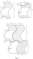
- the present invention discloses a single-piece grinding roller for vertical axis grinders produced by casting a metal matrix in a foundry, said roller comprising at its periphery an openwork reinforcement structure consisting of a plurality of ceramic inserts assembled in a jointed manner, the jointed assembly of the ceramic reinforcements being produced along wavy lines.
- these ceramic inserts are represented schematically.
- these ceramic inserts are infiltrable three-dimensional structures formed by permeable aggregates such as agglomerates of millimetric grains (with an average size of 2 to 8 mm, preferably 3 to 6 mm) aggregated by a glue with millimetric interstices and infiltrable by the casting metal.
- Cast wear parts are widely used in the mining and cement industries for crushing rocks and ores. These include vertical compression mill tables and their grinding rollers in general and truncated and toric grinding rollers in particular, which illustrate the present invention.
- ferrous alloys such as cast iron or steel are combined with the hardness of a ceramic material (such as carbides, nitrides, oxides of various types, etc.), which are highly resistant to wear.
- a ceramic material such as carbides, nitrides, oxides of various types, etc.
- Ceramic reinforcements are generally introduced in the form of bars, i.e. in the form of an insert in which the interstices have already been infiltrated by liquid cast iron and cooled before being reintroduced into a mold to cast the wear part in a single block that is desired.
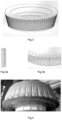
- This technology is illustrated in Figures 3 to 5 of this document and is the subject of the publication WO2005/084809 .
- Maintaining the insert in the mold during casting also requires a certain amount of know-how acquired by manufacturers over the years.
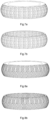
- This reinforcement structure is adapted to the final shape of the roller and is for example of a generally truncated cone or toroidal shape and comprises on its periphery an assembly of ceramic inserts which can take different forms such as for example a side-by-side assembly, therefore adjoining, of inserts having approximately the same dimension as the grinding roller or even a superposition of two or more "rings" of ceramic inserts according to wavy lines.
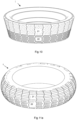
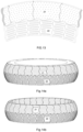
- the assembly on one or more rings depends largely on the final size of the roller since there is always a feasibility limit of an insert for reasons of handling by an operator (mass, volume, friability). This is how a one-ton roller may only require one ring with a limited number of inserts to assemble while a roller of >15 tons will require at least 2 or 3 rings with many superimposed inserts. (See figure 15b For example).
- differentiated opening can be considered depending on the position of the insert in the roller. For example, a different proportion of opening can be considered depending on whether it is the side subjected to the greatest stress, zone 21, or the side subjected to the least stress, zone 22, by wear.
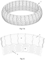
- An example of an assembly of a ring of inserts of this type, for a toric grinding roller is shown in Figure 11a and an example of two superimposed rings is shown in Figures 14a . Three rings of superimposed inserts are shown 15b. To avoid the propagation of wear along a predetermined line, the assembly of the superimposed inserts is preferably done in a staggered pattern.
- the ceramic openwork structures have openings of generally any shape.
- the openings made in the insert structure have a diameter generally between 1 and 10 cm, preferably between 1 and 8 cm and particularly preferably between 2 and 4 cm.
- the peripheral zone most exposed to wear 21 the holes preferably have a truncated cone shape 3 or are associated with blind holes.
- the most exposed zone can also comprise a judicious association of blind holes and through holes.
- blind holes are used, the blind side is placed on the side most stressed by wear.
- truncated cone openings 3 are used, the opening will taper towards the outer surface most exposed to wear.
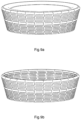
- the holes In the least exposed and most openwork zone 22 the holes have any shape but the cylindrical shape will be preferred. (see figure 12 ).
- Tests were carried out on different rollers according to the invention on a vertical rotary mill of two different types adapted to the rollers to be tested. To neutralize the variable due to the influence of the composition of the ceramic on wear, the same ceramic was used for all the tests. These are millimetric grains of a ceramic metal composite of the titanium carbide type cemented in a metal binder of the manganese steel type. These grains with an average size of approximately 5 mm were compacted to form perforated inserts with a thickness of approximately 50 mm used for all tests.
- Each of the 2 truncated rollers was tested in parallel with a reference roller for 500 hours and the wear was extrapolated to 1000 hours.
- For each of the 3 toric roller tests two rollers were arranged alternately with two reference rollers and rotated for 1000 hours. The tests were carried out continuously. The test conditions are summarized in the table below.
- Crushed material Lignite type coal Silico-calcareous ore Crusher type Polysius RM25/12(Type1) Loesche LM15.2 (Type 2) Type of pebbles Toric Truncated Number of rollers on the crusher 4 2 Mass of the roller (T) 1.4 1 External size 130x33 cm 120/104 x33cm Flow rate (T/h) 27-30 25 Duration of the trial 1000 hours 500 hours Positioning the rollers 2 reference rollers and 2 rollers according to the invention alternately on the same crusher 1 reference roller and a roller according to the invention on the same crusher The determination of the wear of the roller can be carried out from profile measurements, along generatrices, by means of a template resting on surfaces not subject to wear.
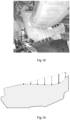
- the distance between the surface of the roller and the template is recorded at several points along the template on a representative number of points on the contour of the roller. (see figure 18 ). These measurements are then compared to the distances recorded. on a new roller. An average wear profile is determined, providing information on the geometry of the wear that can be used by the manufacturer.
- the wear measurement used to compare roller performance is, however, the maximum wear depth on the roller, which determines its replacement. It is this maximum wear that will be used in the table below for performance measurements.
- Grinding rollers made with bars according to WO2005/084809 and represented in the Figures 3, 4 and 5 are used as comparative reference toroidal and truncated cone rollers. These reference rollers are each associated with rollers according to the invention on the same crusher during the test. In the latter, the wear is measured above the bars and not between the bars on the heavily worn ductile matrix.
- all grinding rollers according to the invention exhibit an improvement in wear performance. It is between 10 and 27%, which is significant.
- rollers with differentiated opening depending on the wear stress with zones 21 and 22 have the best performance when the reinforcement insert consists of a single assembly ring with a minimum of joint lines.
- Rollers with several rings superimposed in a staggered manner and differentiated openings have lower performance due to the increase in the number of inserts and therefore of joining lines which will be necessary for large grinding rollers.
- the undifferentiated opening, without specific zones 21 and 22 also allows an improvement in performance of 11% on the toric grinding roller.
Landscapes
- Engineering & Computer Science (AREA)
- Food Science & Technology (AREA)
- Crushing And Grinding (AREA)
- Rolls And Other Rotary Bodies (AREA)
Priority Applications (11)
| Application Number | Priority Date | Filing Date | Title |
|---|---|---|---|
| EP23168749.2A EP4450164A1 (de) | 2023-04-19 | 2023-04-19 | Einteilige verbundschleifrolle |
| PE2025002176A PE20260164A1 (es) | 2023-04-19 | 2024-04-09 | Rodillo de molienda compuesto de una pieza |
| JP2025559686A JP2026512467A (ja) | 2023-04-19 | 2024-04-09 | 一体型複合材粉砕ローラ |
| CN202480021060.3A CN120916847A (zh) | 2023-04-19 | 2024-04-09 | 一体式复合磨辊 |
| PCT/EP2024/059597 WO2024217935A1 (fr) | 2023-04-19 | 2024-04-09 | Galet de broyage composite monobloc |
| EP24718181.1A EP4698323A1 (de) | 2023-04-19 | 2024-04-09 | Einteilige zusammengesetzte mahlwalze |
| KR1020257034844A KR20250174621A (ko) | 2023-04-19 | 2024-04-09 | 일피스 복합 분쇄 롤러 |
| AU2024257974A AU2024257974A1 (en) | 2023-04-19 | 2024-04-09 | One-piece composite grinding roller |
| CONC2025/0012219A CO2025012219A2 (es) | 2023-04-19 | 2025-09-09 | Rodillo de molienda compuesto de una pieza |
| CL2025002876A CL2025002876A1 (es) | 2023-04-19 | 2025-09-24 | Rodillo de molienda compuesto de una pieza |
| MX2025012455A MX2025012455A (es) | 2023-04-19 | 2025-10-17 | Rodillo de molienda compuesto de una pieza |
Applications Claiming Priority (1)
| Application Number | Priority Date | Filing Date | Title |
|---|---|---|---|
| EP23168749.2A EP4450164A1 (de) | 2023-04-19 | 2023-04-19 | Einteilige verbundschleifrolle |
Publications (1)
| Publication Number | Publication Date |
|---|---|
| EP4450164A1 true EP4450164A1 (de) | 2024-10-23 |
Family
ID=86096044
Family Applications (2)
| Application Number | Title | Priority Date | Filing Date |
|---|---|---|---|
| EP23168749.2A Withdrawn EP4450164A1 (de) | 2023-04-19 | 2023-04-19 | Einteilige verbundschleifrolle |
| EP24718181.1A Pending EP4698323A1 (de) | 2023-04-19 | 2024-04-09 | Einteilige zusammengesetzte mahlwalze |
Family Applications After (1)
| Application Number | Title | Priority Date | Filing Date |
|---|---|---|---|
| EP24718181.1A Pending EP4698323A1 (de) | 2023-04-19 | 2024-04-09 | Einteilige zusammengesetzte mahlwalze |
Country Status (10)
| Country | Link |
|---|---|
| EP (2) | EP4450164A1 (de) |
| JP (1) | JP2026512467A (de) |
| KR (1) | KR20250174621A (de) |
| CN (1) | CN120916847A (de) |
| AU (1) | AU2024257974A1 (de) |
| CL (1) | CL2025002876A1 (de) |
| CO (1) | CO2025012219A2 (de) |
| MX (1) | MX2025012455A (de) |
| PE (1) | PE20260164A1 (de) |
| WO (1) | WO2024217935A1 (de) |
Citations (8)
| Publication number | Priority date | Publication date | Assignee | Title |
|---|---|---|---|---|
| WO1998015373A1 (fr) | 1996-10-01 | 1998-04-16 | Hubert Francois | Piece d'usure composite |
| WO2005084809A1 (fr) | 2004-03-03 | 2005-09-15 | Magotteaux International Sa | Galets de broyage pour broyeur vertical |
| WO2014093280A1 (en) * | 2012-12-12 | 2014-06-19 | Flsmidth A/S | Device for comminution of material |
| US20140291428A1 (en) * | 2011-12-21 | 2014-10-02 | Flsmidth A/S | Insert arrangement for a roller wear surface |
| US20180071743A1 (en) * | 2015-03-25 | 2018-03-15 | Flsmidth A/S | A wear-resistant body and a method for producing the same |
| WO2018069006A1 (fr) | 2016-10-12 | 2018-04-19 | Magotteaux International S.A. | Galet de broyage |
| CN111604122A (zh) * | 2020-05-26 | 2020-09-01 | 佛山兴技源科技有限公司 | 磨机、辊压机中带有结构陶瓷瓦板的消耗部件及其制作方法 |
| WO2021160381A1 (fr) | 2020-02-11 | 2021-08-19 | Magotteaux International S.A. | Piece d'usure composite |
-
2023
- 2023-04-19 EP EP23168749.2A patent/EP4450164A1/de not_active Withdrawn
-
2024
- 2024-04-09 JP JP2025559686A patent/JP2026512467A/ja active Pending
- 2024-04-09 KR KR1020257034844A patent/KR20250174621A/ko active Pending
- 2024-04-09 AU AU2024257974A patent/AU2024257974A1/en active Pending
- 2024-04-09 WO PCT/EP2024/059597 patent/WO2024217935A1/fr not_active Ceased
- 2024-04-09 EP EP24718181.1A patent/EP4698323A1/de active Pending
- 2024-04-09 PE PE2025002176A patent/PE20260164A1/es unknown
- 2024-04-09 CN CN202480021060.3A patent/CN120916847A/zh active Pending
-
2025
- 2025-09-09 CO CONC2025/0012219A patent/CO2025012219A2/es unknown
- 2025-09-24 CL CL2025002876A patent/CL2025002876A1/es unknown
- 2025-10-17 MX MX2025012455A patent/MX2025012455A/es unknown
Patent Citations (8)
| Publication number | Priority date | Publication date | Assignee | Title |
|---|---|---|---|---|
| WO1998015373A1 (fr) | 1996-10-01 | 1998-04-16 | Hubert Francois | Piece d'usure composite |
| WO2005084809A1 (fr) | 2004-03-03 | 2005-09-15 | Magotteaux International Sa | Galets de broyage pour broyeur vertical |
| US20140291428A1 (en) * | 2011-12-21 | 2014-10-02 | Flsmidth A/S | Insert arrangement for a roller wear surface |
| WO2014093280A1 (en) * | 2012-12-12 | 2014-06-19 | Flsmidth A/S | Device for comminution of material |
| US20180071743A1 (en) * | 2015-03-25 | 2018-03-15 | Flsmidth A/S | A wear-resistant body and a method for producing the same |
| WO2018069006A1 (fr) | 2016-10-12 | 2018-04-19 | Magotteaux International S.A. | Galet de broyage |
| WO2021160381A1 (fr) | 2020-02-11 | 2021-08-19 | Magotteaux International S.A. | Piece d'usure composite |
| CN111604122A (zh) * | 2020-05-26 | 2020-09-01 | 佛山兴技源科技有限公司 | 磨机、辊压机中带有结构陶瓷瓦板的消耗部件及其制作方法 |
Also Published As
| Publication number | Publication date |
|---|---|
| MX2025012455A (es) | 2025-11-03 |
| CN120916847A (zh) | 2025-11-07 |
| CL2025002876A1 (es) | 2025-11-28 |
| CO2025012219A2 (es) | 2025-09-18 |
| JP2026512467A (ja) | 2026-04-16 |
| WO2024217935A1 (fr) | 2024-10-24 |
| PE20260164A1 (es) | 2026-01-23 |
| AU2024257974A1 (en) | 2025-08-21 |
| EP4698323A1 (de) | 2026-02-25 |
| KR20250174621A (ko) | 2025-12-12 |
Similar Documents
| Publication | Publication Date | Title |
|---|---|---|
| EP2323770B1 (de) | Schlagelement aus verbundmaterial für prallmühle | |
| EP2326738B1 (de) | Mahlkegel für einen kompressionsbrecher | |
| JP5331003B2 (ja) | 多結晶質ダイヤモンド研磨材成形体 | |
| US8517125B2 (en) | Impregnated material with variable erosion properties for rock drilling | |
| EP2329052B1 (de) | Verbundwerkstoffzahn zum bearbeiten von boden oder gestein | |
| EP2334836B9 (de) | Hierarchischer verbundwerkstoff | |
| EP3969206B1 (de) | Verbundverschleissteil | |
| EP3134212B1 (de) | Mahlwalze mit einsätzen von erhöhter grösse | |
| US9103170B2 (en) | Impregnated drill bit | |
| EP3563951A1 (de) | Zahn aus verbundwerkstoff mit kegelstumpfförmigem einsatz | |
| KR20160040241A (ko) | 절단 소자, 절단 소자를 형성하는 관련 방법, 및 관련 지반 천공 공구 | |
| WO2024126484A1 (en) | Composite material | |
| EP4157569A1 (de) | Verschleissteil aus keramik-metall-verbundwerkstoff | |
| EP4385644A1 (de) | Verbundmaterial | |
| EP4698323A1 (de) | Einteilige zusammengesetzte mahlwalze | |
| WO2021239295A1 (fr) | Piece d'usure composite | |
| CN104884197A (zh) | 多晶超硬构造及其制造方法 | |
| GB2450177A (en) | Drill bit with an impregnated cutting structure |
Legal Events
| Date | Code | Title | Description |
|---|---|---|---|
| PUAI | Public reference made under article 153(3) epc to a published international application that has entered the european phase |
Free format text: ORIGINAL CODE: 0009012 |
|
| STAA | Information on the status of an ep patent application or granted ep patent |
Free format text: STATUS: THE APPLICATION HAS BEEN PUBLISHED |
|
| AK | Designated contracting states |
Kind code of ref document: A1 Designated state(s): AL AT BE BG CH CY CZ DE DK EE ES FI FR GB GR HR HU IE IS IT LI LT LU LV MC ME MK MT NL NO PL PT RO RS SE SI SK SM TR |
|
| STAA | Information on the status of an ep patent application or granted ep patent |
Free format text: STATUS: THE APPLICATION IS DEEMED TO BE WITHDRAWN |
|
| 18D | Application deemed to be withdrawn |
Effective date: 20250424 |