EP4450185A1 - Procédé de coulée continue d'acier - Google Patents
Procédé de coulée continue d'acier Download PDFInfo
- Publication number
- EP4450185A1 EP4450185A1 EP23780029.7A EP23780029A EP4450185A1 EP 4450185 A1 EP4450185 A1 EP 4450185A1 EP 23780029 A EP23780029 A EP 23780029A EP 4450185 A1 EP4450185 A1 EP 4450185A1
- Authority
- EP
- European Patent Office
- Prior art keywords
- cast piece
- section
- continuous casting
- solid phase
- phase ratio
- Prior art date
- Legal status (The legal status is an assumption and is not a legal conclusion. Google has not performed a legal analysis and makes no representation as to the accuracy of the status listed.)
- Pending
Links
Images

Classifications
-
- B—PERFORMING OPERATIONS; TRANSPORTING
- B22—CASTING; POWDER METALLURGY
- B22D—CASTING OF METALS; CASTING OF OTHER SUBSTANCES BY THE SAME PROCESSES OR DEVICES
- B22D11/00—Continuous casting of metals, i.e. casting in indefinite lengths
- B22D11/12—Accessories for subsequent treating or working cast stock in situ
- B22D11/124—Accessories for subsequent treating or working cast stock in situ for cooling
-
- B—PERFORMING OPERATIONS; TRANSPORTING
- B22—CASTING; POWDER METALLURGY
- B22D—CASTING OF METALS; CASTING OF OTHER SUBSTANCES BY THE SAME PROCESSES OR DEVICES
- B22D11/00—Continuous casting of metals, i.e. casting in indefinite lengths
- B22D11/12—Accessories for subsequent treating or working cast stock in situ
- B22D11/124—Accessories for subsequent treating or working cast stock in situ for cooling
- B22D11/1246—Nozzles; Spray heads
-
- B—PERFORMING OPERATIONS; TRANSPORTING
- B22—CASTING; POWDER METALLURGY
- B22D—CASTING OF METALS; CASTING OF OTHER SUBSTANCES BY THE SAME PROCESSES OR DEVICES
- B22D11/00—Continuous casting of metals, i.e. casting in indefinite lengths
- B22D11/12—Accessories for subsequent treating or working cast stock in situ
- B22D11/128—Accessories for subsequent treating or working cast stock in situ for removing
-
- B—PERFORMING OPERATIONS; TRANSPORTING
- B22—CASTING; POWDER METALLURGY
- B22D—CASTING OF METALS; CASTING OF OTHER SUBSTANCES BY THE SAME PROCESSES OR DEVICES
- B22D11/00—Continuous casting of metals, i.e. casting in indefinite lengths
- B22D11/16—Controlling or regulating processes or operations
-
- B—PERFORMING OPERATIONS; TRANSPORTING
- B22—CASTING; POWDER METALLURGY
- B22D—CASTING OF METALS; CASTING OF OTHER SUBSTANCES BY THE SAME PROCESSES OR DEVICES
- B22D11/00—Continuous casting of metals, i.e. casting in indefinite lengths
- B22D11/16—Controlling or regulating processes or operations
- B22D11/20—Controlling or regulating processes or operations for removing cast stock
-
- B—PERFORMING OPERATIONS; TRANSPORTING
- B22—CASTING; POWDER METALLURGY
- B22D—CASTING OF METALS; CASTING OF OTHER SUBSTANCES BY THE SAME PROCESSES OR DEVICES
- B22D11/00—Continuous casting of metals, i.e. casting in indefinite lengths
- B22D11/16—Controlling or regulating processes or operations
- B22D11/22—Controlling or regulating processes or operations for cooling cast stock or mould
-
- B—PERFORMING OPERATIONS; TRANSPORTING
- B22—CASTING; POWDER METALLURGY
- B22D—CASTING OF METALS; CASTING OF OTHER SUBSTANCES BY THE SAME PROCESSES OR DEVICES
- B22D11/00—Continuous casting of metals, i.e. casting in indefinite lengths
- B22D11/16—Controlling or regulating processes or operations
- B22D11/22—Controlling or regulating processes or operations for cooling cast stock or mould
- B22D11/225—Controlling or regulating processes or operations for cooling cast stock or mould for secondary cooling
Definitions
- the present invention relates to a steel continuous casting method, and particularly proposes a steel continuous casting method that is effective in reducing center segregation occurring inside a cast piece.
- solute elements such as carbon, phosphorous, sulfur, and manganese
- solute elements are concentrated toward an unsolidified liquid phase side due to redistribution during solidification, resulting in the formation of micro segregation between dendrites.
- a continuous casting piece (hereinafter also referred to simply as a "cast piece") that is solidifying sometimes forms a void or develops a negative pressure at a center part in the thickness of the cast piece due to solidification contraction or thermal contraction or to bulging of a solidification shell that occurs between rolls of the continuous casting machine.
- molten steel is suctioned to the center part in the thickness of the cast piece.
- molten steel between dendrites in which the aforementioned solute elements have concentrated is suctioned and moves to the center part in the thickness and solidifies there.
- a segregation spot thus formed at the center part in the thickness of the cast piece has a far higher value of the concentration of the solute elements compared with the initial concentration in the molten steel. This phenomenon is generally called “macro segregation,” and is also called “center segregation” because of the region where it is present.
- the above-described center segregation of cast piece significantly degrades the quality of steel materials, for example, the quality of line pipe materials for transportation of crude oil, natural gas, etc.
- quality degradation of steel materials is caused, for example, as hydrogen having entered inside steel by a corrosion reaction diffuses and aggregates around manganese sulfide (MnS) or niobium carbide (NbC) having formed at a center segregation part, etc. and causes cracking due to the internal pressure. Since such a center segregation part has hardened due to highly concentrated solute elements, this cracking further propagates and expands to the surrounding area. This cracking is what is called hydrogen-induced cracking (HIC).
- HIC hydrogen-induced cracking
- Patent Literature 1 and Patent Literature 2 propose a technology in which, in a continuous casting machine, a cast piece at a last solidification stage that has an unsolidified layer is cast while being gradually reduced by cast piece support rolls by an amount of reduction approximately corresponding to a sum of a solidification contraction amount and a thermal contraction amount. This technology is called a soft reduction method.
- a soft reduction method when withdrawing a cast piece using a plurality of pairs of cast piece support rolls arranged in a casting direction, the cast piece is gradually reduced by a reduction amount corresponding to the sum of the solidification contraction amount and the thermal contraction amount so as to reduce the volume of the unsolidified layer and thereby prevent the formation of a void and a negative pressure portion at the center part of the cast piece.
- Adopting such a mechanism can prevent the concentrated molten steel between dendrites from being suctioned from between the dendrites to the center part in the thickness of the cast piece, thus mitigating the center segregation occurring inside the cast piece.
- Patent Literature 3 proposes a technology in which a specific water volume at a specific position in a casting direction of a secondary cooling zone of a continuous casting machine is set to 0.5 L/kg-steel or higher to promote refinement and equiaxed crystallization of a solidified structure and thereby reduce the center segregation.
- Patent Literature 4 proposes a technology in which reduction conditions and cooling conditions are appropriately adjusted such that the interval between primary arms of dendrites at a center part in the thickness of a cast piece becomes 1.6 mm or shorter to thereby reduce the center segregation.
- Patent Literature 5 proposes a technology that raises the temperature of the surface of a cast piece by heating as means for temperature control of the cast piece in a continuous casting machine.
- the temperature of a surface layer of the cast piece is raised at an average rate of 30°C/min or more in a straightening zone of the continuous casting machine to thereby prevent surface cracking during straightening of the cast piece.
- adjusting the secondary cooling conditions can refine the solidified structure and reduce the center segregation.
- level of reduction of segregation required for steel pipes, such as line pipe materials has been rising year by year, it is still not adequate for reducing the degree of segregation to such a level as will be required in future.
- To further reduce the segregation for example, continuously casting steel under optimal soft reduction conditions is conceivable, but it is difficult for the methods of Patent Literature 3 and Patent Literature 4 to reduce the center segregation to lower than the current level.
- Patent Literature 5 The cast piece heating device of Patent Literature 5 is limited in terms of installation space in the continuous casting machine. Thus, while this device can be used as local heating means, it does not go so far as to control the entire cast piece to a uniform temperature.
- the present invention is a method developed in view of the above-described problems with the conventional technologies, and an object thereof is to propose a new steel continuous casting method that can effectively reduce the center segregation occurring inside a cast piece.
- a steel continuous casting method characterized in that cooling of a cast piece is performed at a water volume density per surface area of the cast piece in a first section set within a range of 50 L/(m 2 ⁇ min) to 2000 L/(m 2 ⁇ min), inclusive, the first section being a range along a cast piece withdrawing direction in a continuous casting machine, from a start point at which an average value of a solid phase ratio along a thickness direction at a final solidified part in a cast piece width direction is 0.8 or lower to an end point at which the average value of the solid phase ratio along the thickness direction at the final solidified part in the cast piece width direction is higher than the solid phase ratio at the start point but not higher than 1.0.
- Adopting the steel continuous casting method according to the present invention having the above-described essential configuration makes it possible to effectively cool a continuously cast piece and to reduce center segregation and internal cracking that are expected to occur inside the continuously cast piece.
- Fig. 1 is a schematic view showing one example of a continuous casting machine that is effective for implementing a steel continuous casting method according to the present invention.
- a continuous casting machine 11 shown in Fig. 1 is an example of a vertically bent-type continuous casting machine.
- a curved-type or completely vertical-type continuous casting machine can also be used.
- the continuous casting machine 11 shown in Fig. 1 includes a casting mold 13, a tundish 14, a plurality of pairs of cast piece support rolls 16, a plurality of spray nozzles 17, etc. As shown in Fig. 1 , a cast piece 18 is withdrawn in a cast piece withdrawing direction D1. In Fig. 1 , the side of the tundish 14 along the cast piece withdrawing direction D1 and the side toward which the cast piece 18 is withdrawn will be referred to as an upstream side and a downstream side, respectively, for the following description.
- the tundish 14 is provided above the casting mold 13 and serves to supply molten steel 12 to the casting mold 13. Inside the tundish 14, the molten steel 12 supplied from a ladle (not shown) is stored. For this purpose, at the bottom of the tundish 14, a sliding nozzle (not shown) for adjusting the flow rate of the molten steel 12 is installed, and an immersion nozzle 15 is installed on a lower surface of the sliding nozzle.
- the casting mold 13 for continuous casting is installed under the tundish 14, and the molten steel 12 is poured into the casting mold 13 from the tundish 14 through the immersion nozzle 15.
- the poured molten steel 12 is cooled in the casting mold 13 (primary cooling) and thereby the shape of an outer shell of the cast piece 18 is formed.
- the plurality of pairs of cast piece support rolls 16 is provided along the cast piece withdrawing direction D1 so as to support the cast piece 18 from both sides.
- These cast piece support rolls 16 in plurality of pairs are composed of pluralities of pairs of support rolls, for example, support roll pairs, guide roll pairs, and pinch roll pairs.
- a plurality of pairs of cast piece support rolls 16 aggregates to form one segment 20.
- the plurality of spray nozzles 17 is each provided between adjacent cast piece support rolls 16 along the cast piece withdrawing direction D1. These spray nozzles 17 are nozzles for performing secondary cooling of the cast piece 18 by spraying cooling water toward the cast piece 18.
- nozzles such as water spray nozzles (one-fluid spray nozzles) or air mist spray nozzles (two-fluid spray nozzles) can be used.
- the cast piece 18 is withdrawn along the cast piece withdrawing direction D1 while being cooled with the cooling water (secondary cooling water) sprayed from the plurality of spray nozzles 17.
- an unsolidified part 18a of the molten steel inside the cast piece 18 is indicated by hatching.
- a solidification completion position at which the unsolidified part 18a disappears and solidification is completed is indicated by reference sign 18b.
- a downstream-side part of the continuous casting machine 11 is a soft reduction zone 19 in which the cast piece 18 is softly reduced.
- this soft reduction zone 19 a plurality of segments 20a, 20b each formed by a plurality of pairs of cast piece support rolls 16 is provided.
- the plurality of cast piece support rolls 16 in the soft reduction zone 19 is disposed such that a roll interval in a thickness direction of the cast piece 18 between each pair of rolls becomes gradually narrower toward the cast piece withdrawing direction D1.
- Reference sign 22 in Fig. 1 indicates a lower straightening position provided inside the region of the soft reduction zone 19.
- the above-described downstream-side part of the continuous casting machine 11 is also a horizontal-zone region A1 in which the cast piece 18 is carried in a horizontal direction.
- Fig. 1 of the segments each composed of the cast piece support rolls 16, segments present in the horizontal-zone region A1 are indicated by reference sign 20a, and a segment located on the upstream side of the horizontal-zone region A1 is indicated by reference sign 20b.
- a plurality of conveyance rolls 21 for conveying the completely solidified cast piece 18 is provided on the downstream side of the above-described horizontal-zone region A1.
- a cast piece cutting machine (not shown) that cuts the cast piece 18 into predetermined lengths is provided.
- a first section is specified as a section, along the cast piece withdrawing direction D1 in the continuous casting machine 11, from a start point at which an average value of a solid phase ratio along the thickness direction at a width-direction final solidified part at which the solid phase ratio is the lowest in the cast piece width direction is 0.8 or lower, particularly within a range of 0.1 to 0.8, inclusive, to an end point at which the average value of the solid phase ratio along the thickness direction at the width-direction final solidified part at which the solid phase ratio is the lowest in the cast piece width direction is higher than the average value of the solid phase ratio at the start point and within a range not higher than 1.0.
- a section following the above-described first section is specified as a second section, and this second section is a section in which a surface temperature state (nucleate boiling state) after cooling in the first section is complemented until a central solid phase ratio becomes 1.0.
- cooling of the cast piece is performed in the above-described first section by spraying water that is sprayed from the water spray nozzles.
- the water volume density per surface area of the cast piece is set within a range of 50 L/(m 2 ⁇ min) to 2000 L/(m 2 ⁇ min), inclusive. Performing such cooling substantially increases the temperature gradient at the center part in the thickness of the cast piece, so that the solidified structure at the center part in the thickness of the cast piece can be refined to efficiently reduce the center segregation.
- intense cooling cooling the cast piece with cooling water with the water volume density per surface area of the cast piece set within a range of 50 L/(m 2 ⁇ min) to 2000 L/(m 2 ⁇ min), inclusive.
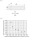
- Fig. 2 is a view in which the position of the width-direction final solidified part at which the solid phase ratio is the lowest in the cast piece width direction is denoted by C1.
- Fig. 2 shows a plan view of the cast piece 18 in the case where an upper surface and a lower surface of the cast piece 18 are supported by the cast piece support rolls 16.
- the direction of "BACK ⁇ -> FRONT” corresponds to the cast piece withdrawing direction D1
- the direction of "RIGHT ⁇ ⁇ LEFT" corresponds to a width direction D2 of the cast piece 18.
- the position C1 of the width-direction final solidified part at which the solid phase ratio is the lowest in the cast piece width direction is located along the cast piece withdrawing direction D1 at a position close to the center part in the width direction of the cast piece 18.
- Fig. 3 is a lateral sectional view of the cast piece 18 cut along a plane perpendicular to the cast piece withdrawing direction D1.
- the direction of "LEFT ⁇ ⁇ RIGHT” corresponds to the width direction D2 of the cast piece 18
- the direction of "UP ⁇ ⁇ DOWN" corresponds to a thickness direction D3 of the cast piece 18.
- a position C2 in the thickness direction of the width-direction final solidified part at which the solid phase ratio is the lowest in the cast piece width direction is, in the lateral cross-section of the cast piece 18, a position parallel to the thickness direction D3 at C1 and indicated by the broken line in Fig. 3 .
- a regression formula is used for a coefficient of heat transfer of cooling from the surface of the cast piece by water spraying, and for other steel-related physical values, physical values corresponding to the respective temperatures from a data book are used, and at each of temperatures for which data is not available, values obtained by performing a proportional calculation using data at temperatures immediately below and immediately above that temperature were used.
- a cross-sectional temperature distribution of the cast piece was obtained by performing a non-steady heat transfer and solidification analysis based on the premise as described above.
- the solid phase ratio at a certain position optionally selected in the thickness direction of the cross-section of the cast piece can be calculated using a temperature at the optionally selected position, a solidus-line temperature of the molten steel, and a liquidus-line temperature of the molten steel, and the temperature at the optionally selected position was determined using the aforementioned cross-sectional temperature distribution of the cast piece.
- the solid phase ratio is 1.0
- the solid phase ratio is 0.
- the solid phase ratio is a value more than 0 but less than 1.0, and is determined by the temperature at the position.
- the water volume density per surface area of the cast piece is set within a range of 50 L/(m 2 ⁇ min) to 2000 L/(m 2 ⁇ min), inclusive, in the first section.
- the water volume density per surface area of the cast piece in this first section is more preferably set to 300 L/(m 2 ⁇ min) or more.
- neither of the temperature gradient at the last solidification stage and the number of segregated grains was found to differ significantly between when the water volume density per surface area of the cast piece in the first section was set to 2000 L/(m 2 ⁇ min) and when it was set to 1000 L/(m 2 ⁇ min). Since setting the water volume density lower can reduce the required water volume and thereby cut the cost, setting the water volume density to 1000 L/(m 2 ⁇ min) or less is desirable.
- the difference in the average value of the solid phase ratio between the start point and the end point is preferably 0.2 or more, and more preferably 0.4 or more.
- the start point of the first section be located either in the horizontal zone in which the cast piece is conveyed in the horizontal direction or in the curved zone that is located on the upstream side of the horizontal zone.
- the first section be within the horizontal-zone region A1 in which the cast piece is conveyed in the horizontal direction. This is because when intense cooling is performed in the horizontal-zone region, the cast piece can be evenly cooled so as to mitigate the influence of thermal stress, which makes internal cracking of the cast piece even less likely to occur.
- the effect of the present invention can be achieved also when the start point of the first section is in the curved zone. While it is possible that straightening may become impossible due to a decrease in temperature or a problem such as cracking due to surface stress may occur, the case where the start point of the first section is located in the curved zone falls within an allowable range of the present invention.
- the water volume density per surface area of the cast piece should be lower than the water volume density per surface area of the cast piece in the first section, and the flow rate should be such that the surface temperature of the cast piece can be held at 200°C or lower.
- cooling at a water volume density equivalent to that in the first section is expensive in terms of equipment.
- doing as specified above can keep the equipment investment cost down and yet achieve an effect equivalent to that when intense cooling is performed only in the first section.
- another effect is achieved in that rapid heat recuperation is restricted to prevent internal cracking of the cast piece due to heat recuperation.
- the cast piece be cooled in the second section by water spraying with the water volume density per surface area of the cast piece set within a range of 50 L/(m 2 ⁇ min) to 300 L/(m 2 ⁇ min), inclusive.
- the surface temperature of the cast piece refers to a temperature at the center position in the width of an outermost surface of the cast piece in the aforementioned cross-sectional temperature distribution of the cast piece obtained by the non-steady heat transfer and solidification analysis. While this calculated value is used as the surface temperature in the present invention, the surface temperature of the cast piece can also be actually measured. When actually measuring the surface temperature, the temperature of the outermost surface of the cast piece is measured as the surface temperature using, for example, a radiation thermometer or a thermocouple.
- the cast piece is softly reduced from long-side surfaces at a reduction rate of 0.3 to 2.0 mm/min in the first section and the second section. This is because doing so can restrict suctioning of the concentrated molten steel due to solidification contraction.
- the roll gap of the plurality of pairs of cast piece support rolls is incrementally increased toward the downstream side within a range not including a straightening point (starting at or after upper straightening and ending before lower straightening, and the degree is set flat at the straightening point so as not to change the constriction as far as possible) so as to bulge the long-side surfaces of the cast piece by a total bulging amount of 2 to 20 mm, and then the roll gap of the plurality of pairs of cast piece support rolls is incrementally reduced toward the downstream side in the casting direction so as to softly reduce the cast piece by such a total amount that it is not reduced beyond thermal contraction of the short sides.
- a further improvement in efficiency can be expected.
- medium-carbon aluminum killed steel was cast.
- the machine length of the continuous casting machine was 49 m; the thickness of a cast piece was 250 mm; the width of the cast piece was 2100 mm; secondary cooling was performed using air mist spraying except for the first section and the second section; and the range of the second cooling was from immediately under the casting mold to the outlet of the continuous casting machine.
- concentrations of ingredient components in the medium-carbon aluminum killed steel used are as follows: carbon (C): 0.20 mass%, silicon (Si): 0.25 mass%, manganese (Mn): 1.1 mass%, phosphorous (P): 0.01 mass%, and sulfur (S): 0.002 mass%.
- the solidification completion position of the cast piece and the temperature gradient near the center in the thickness at the last solidification stage are defined as described below.
- the internal crack length, and the cutting of the cast piece those measured as follows were used, and were used for evaluations of the degree of segregation, the internal cracking, and the cutting, respectively.
- cutting refers to a void in a cast piece that appears as molten steel which remains in a closed space between dendrites during solidification and in which segregation components have concentrated contracts in volume during solidification.
- the solidification completion position of the cast piece was calculated by a non-steady heat transfer and solidification analysis.
- the temperature gradient near the center in the thickness of the cast piece at the last solidification stage was calculated using the aforementioned non-steady heat transfer and solidification analysis.
- the number of segregated grains was measured by the following method and used for the evaluation of segregation.
- a cast piece sample was taken that had a width of 15 mm, included a center segregation part at its center part, and had a length from the center in the width to a triple point (a point at which solidification shells on the short-edge side and the long-edge side that have grown met) on one side.
- a cross-section perpendicular to the cast piece withdrawing direction D1 of the cast piece sample taken was ground, and a segregation zone was revealed by, for example, corroding the surface with a saturated aqueous solution of picric acid etc., and a range of ⁇ 7.5 mm in the thickness of the cast piece from the center of this segregation zone was regarded as a center segregation part.
- the cast piece sample in the segregation zone near the center in the thickness (near the solidification completion part) was divided into small parts in the cast piece width direction, and then the concentration of manganese (Mn) in the cast piece samples was surface analyzed over the entire surface using an electron probe micro analyzer (EPMA), with an electron beam diameter of 100 ⁇ m.
- EPMA electron probe micro analyzer
- a distribution of the degree of segregation of manganese (Mn) was obtained, and regions with a degree of Mn segregation of 1.33 or higher that are connected were regarded as one segregated grain.
- the number of segregated grains was counted, and the number of segregated grains divided by the length of the sample in the cast piece width direction was regarded as the number of segregated grains (piece/mm).
- the degree of Mn segregation is the Mn concentration at the segregation part divided by the Mn concentration at a position 10 mm away from the center part in the thickness.
- the internal crack length of the cast piece was measured by the following method and used for the evaluation of internal cracking.
- the cross-section of the cast piece after completion of solidification perpendicular to the cast piece withdrawing direction D1 was subjected to milling and then hydrochloric acid etching. Then, a macro print was taken and checked for cutting by a visual sensory inspection. A cross-section in which no cutting was recognized were determined as "good” (circle), and a cross-section in which slight cutting that did not affect the product quality were determined as "fair” (triangle).
- the present inventors conducted the following experiments to study the conditions for reducing the center segregation.
- the water volume density per surface area of the cast piece should be set to 2000 L/(m 2 ⁇ min) or less, preferably 1000 L/(m 2 ⁇ min) or less.
- the lower limit should be 50 L/(m 2 ⁇ min) or more, preferably 300 L/(m 2 ⁇ min) or more.
- the effect of cooling the cast piece was studied. According to a finding of the present inventors, the effect of cooling the cast piece was found to be significantly influenced by the surface temperature of the cast piece.
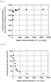
- a possible explanation is that the form of boiling of cooling water varies according to the surface temperature of the cast piece. If the surface temperature of the cast piece has decreased sufficiently, the form of boiling in a surface layer becomes nucleate boiling, which can achieve stable cooling. Therefore, the condition of the water volume density per surface area of the cast piece in water spraying was varied during secondary cooling of the cast piece using a continuous casting machine, and the time taken for the surface temperature of the cast piece to decrease from 800°C to 300°C (temperature decrease time) was calculated to study the influence of the water volume density on the temperature decrease time. A graph on which the result is plotted is shown in Fig. 6 .
- the temperature decrease time for the surface temperature of the cast piece to decrease from 800°C to 300°C was less than 200 seconds when the water volume density per surface area of the cast piece was near 50 L/(m 2 ⁇ min), and that therefore a water volume density per surface area of the cast piece of 50 L/(m 2 ⁇ min) or more was preferable.
- the decrease time did not change significantly.
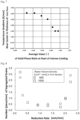
- the present inventors also studied the start position of intense cooling that allowed the temperature gradient at the center part in the thickness of the cast piece to be efficiently increased.
- the cast piece was cooled while the condition of the average value of the solid phase ratio along the thickness direction of the cast piece at the start of intense cooling was varied, and a relationship between the average value of the solid phase ratio at the start of intense cooling and the temperature gradient near the center in the thickness of the cast piece at the last solidification stage was studied.
- the thickness of the cast piece was 250 mm, and the water volume density per surface area of the cast piece during intense cooling was 300 L/(m 2 ⁇ min), and the intense cooling was continued up to the complete solidification position of the cast piece.
- a graph on which the result about the relationship between the average value of the solid phase ratio at the start of intense cooling and the temperature gradient near the center in the thickness of the cast piece at the last solidification stage is plotted is shown in Fig. 7 .
- medium-carbon aluminum killed steel was cast.
- the machine length of the continuous casting machine was 49 m; the thickness of a cast piece was 250 mm; the width of the cast piece was 2100 mm, secondary cooling was performed using air mist spraying except for the first section and the second section; and the range of the second cooling was from immediately under the casting mold to the outlet of the continuous casting machine.
- concentrations of ingredient components in the medium-carbon aluminum killed steel used were as follows: carbon (C): 0.20 mass%, silicon (Si): 0.25 mass%, manganese (Mn): 1.1 mass%, phosphorous (P): 0.01 mass%, and sulfur (S): 0.002 mass%.
- No. 1 to 7 and No. 10 to 14 are all examples in which operation was conducted using the conditions required for operation in the first section that were within the ranges complying with the present invention. As a result, the evaluation of the degree of segregation and the evaluation of the internal cracking were both good.
- No. 8 shown as a comparative example is an example in which the water volume density in the first section is outside the range
- No. 9 is an example in which the solid phase ratio at the start point is outside the range.
- No. 8 with a low water volume density the nucleate boiling state failed to be maintained, and the evaluation of the number of segregated grains and the evaluation of the internal cracking were both poor.
- No. 8 with a low water volume density the nucleate boiling state failed to be maintained, and the evaluation of the number of segregated grains and the evaluation of the internal cracking were both poor.
- No. 8 with a low water volume density the nucleate boiling state failed to be maintained, and the evaluation of the number of segregated grains and the evaluation of the internal cracking
- a possible cause is as follows.
- the temperature gradient increases and refinement of dendrites can be achieved.
- combining soft reduction is preferable.
- soft reduction is too weak, i.e., the reduction rate is too low, a flow accompanying solidification contraction cannot be inhibited and normal segregation occurs.
- cutting due to solidification contraction may occur.
- soft reduction is too strong, i.e., the reduction rate is too fast, reduction becomes excessive, so that concentrated molten steel flows backward and causes inverted-V segregation, thus exacerbating the segregation.
- the unit of volume "L” in this Description is 10 -3 m 3 .
- An expression of a range of numerical values "x to y” means x or more but y or less, including boundary values.
Landscapes
- Engineering & Computer Science (AREA)
- Mechanical Engineering (AREA)
- Continuous Casting (AREA)
Applications Claiming Priority (2)
| Application Number | Priority Date | Filing Date | Title |
|---|---|---|---|
| JP2022051592 | 2022-03-28 | ||
| PCT/JP2023/011463 WO2023190018A1 (fr) | 2022-03-28 | 2023-03-23 | Procédé de coulée continue d'acier |
Publications (2)
| Publication Number | Publication Date |
|---|---|
| EP4450185A1 true EP4450185A1 (fr) | 2024-10-23 |
| EP4450185A4 EP4450185A4 (fr) | 2025-04-09 |
Family
ID=88198264
Family Applications (1)
| Application Number | Title | Priority Date | Filing Date |
|---|---|---|---|
| EP23780029.7A Pending EP4450185A4 (fr) | 2022-03-28 | 2023-03-23 | Procédé de coulée continue d'acier |
Country Status (5)
| Country | Link |
|---|---|
| US (1) | US20250144702A1 (fr) |
| EP (1) | EP4450185A4 (fr) |
| JP (1) | JP7355285B1 (fr) |
| KR (1) | KR20240162540A (fr) |
| CN (1) | CN119053396A (fr) |
Family Cites Families (11)
| Publication number | Priority date | Publication date | Assignee | Title |
|---|---|---|---|---|
| JP2856068B2 (ja) * | 1993-04-20 | 1999-02-10 | 住友金属工業株式会社 | 連続鋳造における鋳片の冷却方法 |
| JP3064832B2 (ja) | 1994-11-10 | 2000-07-12 | 住友金属工業株式会社 | 連続鋳造方法 |
| JPH08192256A (ja) | 1995-01-12 | 1996-07-30 | Nippon Steel Corp | 連続鋳造方法 |
| JPH08224650A (ja) | 1995-02-22 | 1996-09-03 | Nippon Steel Corp | 鋼の連鋳鋳片の偏析、センターポロシティ改善方法 |
| JP3401785B2 (ja) * | 1999-08-27 | 2003-04-28 | 住友金属工業株式会社 | 連続鋳造における鋳片の冷却方法 |
| JP4690995B2 (ja) | 2006-10-18 | 2011-06-01 | 新日本製鐵株式会社 | 鋼の連続鋳造方法及び連続鋳造設備 |
| JP5962206B2 (ja) * | 2012-05-23 | 2016-08-03 | Jfeスチール株式会社 | 高Cr鋼継目無鋼管製管用丸鋳片の製造方法 |
| WO2014020860A1 (fr) * | 2012-07-31 | 2014-02-06 | Jfeスチール株式会社 | Procédé de coulée continue d'acier |
| JP6115735B2 (ja) | 2014-07-25 | 2017-04-19 | Jfeスチール株式会社 | 鋼の連続鋳造方法 |
| JP7047495B2 (ja) * | 2018-03-13 | 2022-04-05 | 日本製鉄株式会社 | 鋳片の連続鋳造方法 |
| EP3932586A4 (fr) * | 2019-04-02 | 2022-05-04 | JFE Steel Corporation | Procédé de coulée continue d'acier |
-
2023
- 2023-03-23 JP JP2023538740A patent/JP7355285B1/ja active Active
- 2023-03-23 CN CN202380030669.2A patent/CN119053396A/zh active Pending
- 2023-03-23 EP EP23780029.7A patent/EP4450185A4/fr active Pending
- 2023-03-23 KR KR1020247034145A patent/KR20240162540A/ko active Pending
- 2023-03-23 US US18/730,104 patent/US20250144702A1/en active Pending
Also Published As
| Publication number | Publication date |
|---|---|
| EP4450185A4 (fr) | 2025-04-09 |
| KR20240162540A (ko) | 2024-11-15 |
| JPWO2023190018A1 (fr) | 2023-10-05 |
| US20250144702A1 (en) | 2025-05-08 |
| JP7355285B1 (ja) | 2023-10-03 |
| CN119053396A (zh) | 2024-11-29 |
Similar Documents
| Publication | Publication Date | Title |
|---|---|---|
| TWI787597B (zh) | 鋼之連續鑄造方法 | |
| JP6115735B2 (ja) | 鋼の連続鋳造方法 | |
| JP5962625B2 (ja) | 鋼の連続鋳造方法 | |
| JP6384679B2 (ja) | 熱延鋼板の製造方法 | |
| EP3488947B1 (fr) | Procédé de coulée continue d'acier | |
| TWI753487B (zh) | 連續鑄造鑄片之二次冷卻方法及裝置 | |
| EP4052815B1 (fr) | Procédé de refroidissement secondaire pour dalle de coulée continue | |
| EP3998126A1 (fr) | Procédé de refroidissement secondaire et appareil de refroidissement secondaire pour brame de coulée continue | |
| EP4450185A1 (fr) | Procédé de coulée continue d'acier | |
| US11471936B2 (en) | Continuous casting method of steel | |
| JP2016179490A (ja) | 連続鋳造方法 | |
| WO2023190018A1 (fr) | Procédé de coulée continue d'acier | |
| US20250353074A1 (en) | Continuous casting method and continuous casting machine for steel | |
| RU2779384C1 (ru) | Способ непрерывной разливки стали | |
| EP4501490A1 (fr) | Équipement de coulée continue de dalle coulée et procédé de coulée continue de dalle coulée | |
| JP7817540B2 (ja) | 鋼の連続鋳造方法 | |
| JP2025171416A (ja) | 鋼の連続鋳造方法 | |
| JP2016036821A (ja) | 連続鋳造方法 |
Legal Events
| Date | Code | Title | Description |
|---|---|---|---|
| STAA | Information on the status of an ep patent application or granted ep patent |
Free format text: STATUS: THE INTERNATIONAL PUBLICATION HAS BEEN MADE |
|
| PUAI | Public reference made under article 153(3) epc to a published international application that has entered the european phase |
Free format text: ORIGINAL CODE: 0009012 |
|
| STAA | Information on the status of an ep patent application or granted ep patent |
Free format text: STATUS: REQUEST FOR EXAMINATION WAS MADE |
|
| 17P | Request for examination filed |
Effective date: 20240716 |
|
| AK | Designated contracting states |
Kind code of ref document: A1 Designated state(s): AL AT BE BG CH CY CZ DE DK EE ES FI FR GB GR HR HU IE IS IT LI LT LU LV MC ME MK MT NL NO PL PT RO RS SE SI SK SM TR |
|
| A4 | Supplementary search report drawn up and despatched |
Effective date: 20250311 |
|
| RIC1 | Information provided on ipc code assigned before grant |
Ipc: B22D 11/12 20060101ALI20250305BHEP Ipc: B22D 11/16 20060101ALI20250305BHEP Ipc: B22D 11/22 20060101ALI20250305BHEP Ipc: B22D 11/20 20060101ALI20250305BHEP Ipc: B22D 11/128 20060101ALI20250305BHEP Ipc: B22D 11/124 20060101AFI20250305BHEP |
|
| DAV | Request for validation of the european patent (deleted) | ||
| DAX | Request for extension of the european patent (deleted) | ||
| STAA | Information on the status of an ep patent application or granted ep patent |
Free format text: STATUS: EXAMINATION IS IN PROGRESS |
|
| 17Q | First examination report despatched |
Effective date: 20250812 |
|
| GRAP | Despatch of communication of intention to grant a patent |
Free format text: ORIGINAL CODE: EPIDOSNIGR1 |
|
| STAA | Information on the status of an ep patent application or granted ep patent |
Free format text: STATUS: GRANT OF PATENT IS INTENDED |
|
| RIC1 | Information provided on ipc code assigned before grant |
Ipc: B22D 11/124 20060101AFI20260106BHEP Ipc: B22D 11/128 20060101ALI20260106BHEP Ipc: B22D 11/20 20060101ALI20260106BHEP Ipc: B22D 11/16 20060101ALI20260106BHEP Ipc: B22D 11/22 20060101ALI20260106BHEP |
|
| INTG | Intention to grant announced |
Effective date: 20260127 |