EP4450231A1 - Outil électrique - Google Patents
Outil électrique Download PDFInfo
- Publication number
- EP4450231A1 EP4450231A1 EP24163324.7A EP24163324A EP4450231A1 EP 4450231 A1 EP4450231 A1 EP 4450231A1 EP 24163324 A EP24163324 A EP 24163324A EP 4450231 A1 EP4450231 A1 EP 4450231A1
- Authority
- EP
- European Patent Office
- Prior art keywords
- magnetic separator
- separator device
- cooling air
- flow
- housing
- Prior art date
- Legal status (The legal status is an assumption and is not a legal conclusion. Google has not performed a legal analysis and makes no representation as to the accuracy of the status listed.)
- Pending
Links
Images




Classifications
-
- B—PERFORMING OPERATIONS; TRANSPORTING
- B25—HAND TOOLS; PORTABLE POWER-DRIVEN TOOLS; MANIPULATORS
- B25F—COMBINATION OR MULTI-PURPOSE TOOLS NOT OTHERWISE PROVIDED FOR; DETAILS OR COMPONENTS OF PORTABLE POWER-DRIVEN TOOLS NOT PARTICULARLY RELATED TO THE OPERATIONS PERFORMED AND NOT OTHERWISE PROVIDED FOR
- B25F5/00—Details or components of portable power-driven tools not particularly related to the operations performed and not otherwise provided for
- B25F5/008—Cooling means
-
- B—PERFORMING OPERATIONS; TRANSPORTING
- B28—WORKING CEMENT, CLAY, OR STONE
- B28D—WORKING STONE OR STONE-LIKE MATERIALS
- B28D7/00—Accessories specially adapted for use with machines or devices of the preceding groups
- B28D7/02—Accessories specially adapted for use with machines or devices of the preceding groups for removing or laying dust, e.g. by spraying liquids; for cooling work
-
- B—PERFORMING OPERATIONS; TRANSPORTING
- B03—SEPARATION OF SOLID MATERIALS USING LIQUIDS OR USING PNEUMATIC TABLES OR JIGS; MAGNETIC OR ELECTROSTATIC SEPARATION OF SOLID MATERIALS FROM SOLID MATERIALS OR FLUIDS; SEPARATION BY HIGH-VOLTAGE ELECTRIC FIELDS
- B03C—MAGNETIC OR ELECTROSTATIC SEPARATION OF SOLID MATERIALS FROM SOLID MATERIALS OR FLUIDS; SEPARATION BY HIGH-VOLTAGE ELECTRIC FIELDS
- B03C1/00—Magnetic separation
- B03C1/02—Magnetic separation acting directly on the substance being separated
-
- H—ELECTRICITY
- H02—GENERATION; CONVERSION OR DISTRIBUTION OF ELECTRIC POWER
- H02K—DYNAMO-ELECTRIC MACHINES
- H02K5/00—Casings; Enclosures; Supports
- H02K5/04—Casings or enclosures characterised by the shape, form or construction thereof
- H02K5/20—Casings or enclosures characterised by the shape, form or construction thereof with channels or ducts for flow of cooling medium
-
- H—ELECTRICITY
- H02—GENERATION; CONVERSION OR DISTRIBUTION OF ELECTRIC POWER
- H02K—DYNAMO-ELECTRIC MACHINES
- H02K5/00—Casings; Enclosures; Supports
- H02K5/04—Casings or enclosures characterised by the shape, form or construction thereof
- H02K5/20—Casings or enclosures characterised by the shape, form or construction thereof with channels or ducts for flow of cooling medium
- H02K5/207—Casings or enclosures characterised by the shape, form or construction thereof with channels or ducts for flow of cooling medium with openings in the casing specially adapted for ambient air
-
- H—ELECTRICITY
- H02—GENERATION; CONVERSION OR DISTRIBUTION OF ELECTRIC POWER
- H02K—DYNAMO-ELECTRIC MACHINES
- H02K9/00—Arrangements for cooling or ventilating
- H02K9/26—Structural association of machines with devices for cleaning or drying cooling medium, e.g. with filters
Definitions
- the invention relates to an electrical working device according to the features of the preamble of claim 1.
- Electrical tools comprise a housing and a drive motor arranged in the housing.
- the drive motor is designed as an electric motor.
- a tool of the tool is driven by the drive motor.
- To cool the drive motor such a tool usually comprises a cooling air duct.
- a cooling air stream flows along the cooling air duct and flows through the drive motor to cool it.
- ferromagnetic particles are transported into the housing with the cooling air flow.
- Known tools include magnetic separators that are designed to attract ferromagnetic particles adhering to the electric motor in order to free the electric motor of these particles.
- the magnetic separator device is arranged upstream of the drive motor in relation to the cooling air flow in the curved channel section of the cooling air channel.
- the ferromagnetic particles are separated from the cooling air flow before they can reach the drive motor.
- the ferromagnetic particles no longer follow the main air flow, but are accelerated out of the main flow into the outer area of the channel section by the centrifugal forces acting on them due to their comparatively high weight.
- the ferromagnetic particles exit the main flow, they are slowed down and then attracted to the magnetic separator and attached to it.
- upstream means "against the direction of flow”.
- downstream means "in the direction of flow”.
- the cooling air flow in the curved channel section has a main flow, and the main flow runs essentially perpendicular to a first flow plane and perpendicular to a second flow plane, wherein the first flow plane and the second flow plane enclose an angle, wherein the angle is at least 10°, preferably at least 30°, particularly preferably at least 60°, in particular at least 80°.
- the angle between the first flow plane and the second flow plane increases, the radius of the curve through which the main flow flows along the curved channel section also becomes smaller, at least indirectly.
- the centrifugal force also increases, whereby the ferromagnetic particles can be separated even more efficiently from the cooling air flow.
- the magnetic separator device extends between the two flow planes over an angle ⁇ that is at least 10°, in particular at least 30°, particularly preferably at least 50°.
- ⁇ that is at least 10°, in particular at least 30°, particularly preferably at least 50°.
- the magnetic separator device is located in the direction of the main flow in the first flow plane in overlap with the main flow.
- the main flow at the beginning of the curved channel section preferably flows in the direction of the magnetic separator device.
- the magnetic separator device is advantageously located opposite to the direction of the main flow in the second flow plane, overlapping the main flow. The main flow therefore flows away from the magnetic separator device after the ferromagnetic particles have been thrown onto the magnetic separator device by centrifugal force.
- the curved channel section has an inner side and an outer side in its channel interior in the region of the curve, wherein the distance between the magnetic separator device and the outer side is smaller than the distance between the magnetic separator device and the inner side.
- the magnetic separator device By arranging the magnetic separator device close to the outside of the curved channel section, the air flow can flow between the channel inner side of the curved channel section and the magnetic separator device, wherein the ferromagnetic parts are thrown directly onto the magnetic separator device.
- the magnetic separator device extends along a longitudinal axis and is arranged approximately tangentially to the main flow with respect to its longitudinal axis. The main flow is thus not blocked by the magnetic separator device, and accordingly the magnetic separator device does not form any significant resistance to the main flow.
- the magnetic separator device is detachably held on the housing.
- the magnetic separator device can thus be removed from the housing of the working device, easily cleaned and then reattached to the housing.
- the curved channel section in the area of the magnetic separator device can also be cleaned. This also makes it possible to easily replace defective parts of the magnetic separator device.
- the magnetic separator device particularly preferably comprises a carrier and at least one permanent magnet held in/on the carrier.
- the magnetic separator device advantageously comprises several permanent magnets, in particular at least three permanent magnets.
- the permanent magnets are preferably arranged one behind the other in the direction of the longitudinal axis of the magnetic separator device. Other arrangements of the permanent magnets can also be expedient.
- the size and number of permanent magnets are to be designed primarily depending on the size of the cooling air channel and the size of the volume flow of the cooling air.
- the curved channel section has a first longitudinal side and a second longitudinal side opposite the first longitudinal side, wherein the magnetic separator device is arranged in the curved channel section in such a way that the magnetic separator device can be flowed around in the region of the at least one permanent magnet both on a first side of the magnetic separator device facing the first longitudinal side of the channel section and on a second side of the magnetic separator device facing the second longitudinal side of the channel section.
- the side surfaces of the magnetic separator device are arranged at a distance from the first longitudinal side and the second longitudinal side of the curved channel section. This leads to an even lower flow resistance of the cooling air flow.
- the ferromagnetic particles can be collected on the magnetic separator device in this region.
- the housing comprises a ventilation grille with at least one inlet opening for the cooling air flow, wherein the inlet opening is part of the cooling air duct and opens into the curved duct section.
- the inlet opening forms a drainage opening of the cooling air duct.
- the drainage opening is designed in such a way that all liquid in the area of the inlet opening can flow out into the environment via the ventilation grille.
- a reservoir for collecting dirt particles, in particular mineral dirt particles, is provided in the cooling air duct in the region of the inlet opening.
- Fig. 1 shows a cutting grinder as an embodiment of an electrical working device 1 according to the invention.
- An alternative embodiment of the A working device 1 for example as a motor chainsaw, is possible.
- the working device 1 is a hand-guided, hand-carried working device 1.
- the working device 1 is carried and guided by the operator during operation.
- the working device 1 has a housing 2 on which a handle 53 and a handle tube 54 are arranged for guiding the working device 1 during operation. Other handles can also be provided.
- a drive motor 3 is arranged in the housing 2.
- the drive motor 3 is only shown schematically by a dashed rectangle.
- An operating element 6 for controlling the drive motor 3 is provided on the rear handle 3.
- the drive motor 3 is an electric motor.
- the electric motor is supplied with energy by a battery 7 held in the housing 2.
- the working device 1 comprises a boom 8 which is attached to the housing 2 at one end.
- the boom 8 has a free end 51 which projects away from the housing 2.
- a tool 5 is rotatably mounted on the free end 51 of the boom 8.
- the tool 5 is only indicated schematically. In the embodiment, the tool 5 is a cutting disc.
- a protective hood 10 is attached to the boom 8. The protective hood 10 covers the tool 5 over part of its circumference.
- the housing 2 extends along a longitudinal center axis 36 from a rear end 34 to a front end 35.
- the rear end 34 of the housing 2 is formed on the handle 53.
- the boom 8 with the tool 5 arranged on the boom 8 extends beyond the front end 35 of the housing 2.
- the housing 2 also comprises an upper side 44 and a lower side 45, wherein the working device 1 can be placed on the floor 40 on the lower side 45.
- the upper side 44 and the lower side 45 are connected to one another by a first longitudinal side 46 and a second longitudinal side 47.
- the working device 1 comprises a control unit 55 arranged in the housing 2.
- the control unit 55 is in Fig. 1 schematically represented by a dashed rectangle.
- the control unit 55 processes signals which are Control elements 6 and essentially serves to control the drive motor 3.
- the working device 1 comprises at least one cooling air duct 10 for guiding a cooling air flow 11 ( Fig. 4 ).
- the drive motor 3, which is designed as an electric motor, is cooled by means of the cooling air flow 11 during operation of the working device 1.
- other components, in particular electronic components, of the working device 1 are to be cooled.
- Such electronic components are, for example, the control unit 55.
- a channel inlet 26 and a channel outlet 27 are provided in the housing 2.
- the cooling air flow 11 flows into the cooling air channel 10 via the channel inlet 26.
- the cooling air flow 11 then flows through the cooling air channel 10 and cools the control unit 55 and the drive motor 3.
- the cooling air flow 11 flows out of the cooling air channel 10 into the environment via the channel outlet 27.
- the channel inlet 26 is arranged in the embodiment on the first longitudinal side 46 of the housing 2.
- the channel inlet 26 is formed by a first ventilation grille 30 of the housing 2.
- the channel outlet 27 is formed on the underside 45 of the housing 2.
- the channel outlet 27 is formed by a second ventilation grille 28 of the housing 2.
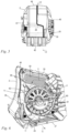
- FIG. 3 shows a detail of the working device 1 according to the invention in a side view.
- Fig. 4 shows a perspective sectional view according to the line between the arrows IV in Fig. 3 .
- the first longitudinal side 46 of the housing 2 is shown.
- the channel inlet 26 is formed by the first ventilation grille 30.
- the cooling air flow 11 flows from the outside environment into the cooling air channel 10 via the channel inlet 26. From there, the cooling air flow 11 flows in the direction of the rear end 34 of the housing 2 into a curved channel section 12.
- the curved channel section 12 guides the Cooling air flow 11 in the direction of the top side 44 of the housing 2.
- the cooling air channel 10 then runs in the direction of the second longitudinal side 47 along a transverse section 56.
- the transverse section 56 is part of the housing 2.
- An opening 57 for a screw dome is provided in the transverse section 56.
- FIG. 5 the front view of the housing 2 of the working device 1 is shown.
- FIG. 6 is a partial, perspective sectional view of the working device 1 along the line between the arrows VI in Fig. 5 shown.
- the control unit 55 is attached to the housing 2.
- a heat sink 58 is arranged on the control unit 55, in particular on an underside 59 of the control unit 55.
- the heat sink 58 is formed from a large number of individual rods which are arranged at a distance from one another.
- the cooling air flow 11 flows around the control unit 55.
- the cooling air flow also flows through the heat sink 58, whereby the heat is dissipated from the control unit 55.
- cooling air flow 11 flows around other electronics of the work device (not shown in detail), for example the phase connections of the electric motor, etc.
- the cooling air channel 10 continues into a spiral housing 62. Accordingly, the cooling air flow 11 flows from the control unit 55 into the spiral housing 62.
- the drive motor 3 in particular an electric motor, is arranged in the spiral housing 62.
- the drive motor 3 has a drive shaft 60.
- a fan wheel 61 is attached to the drive shaft 60 and is driven in rotation by the drive motor 3.
- the fan wheel 61 When the work device 1 is in operation, the fan wheel 61 generates a negative pressure in the spiral housing 62, whereby the cooling air flow 11 is generated.
- the cooling air flow 11 flows around the drive motor 3 in the spiral housing 62 up to the fan wheel 61.
- the cooling air flow 11 is guided by the fan wheel 61 via a diffuser 63 through the duct outlet 27 into the outside environment.
- a perspective view of the spiral housing 62 is shown.
- the spiral housing 62 comprises a support device 64 for receiving the control unit 55.
- Other electronic components of the working device 1 can also be attached to the support device 64. or supported.
- the support device 64 is formed from a rectangular frame.
- the control device 55 and the heat sink 58 are accommodated in the frame ( Fig. 6 ).
- To ensure sufficient rigidity of the support device 64 several stiffening ribs 66 are formed on it, which preferably extend into the center of the spiral 67.
- the spiral housing 62 is formed in one piece.
- the spiral housing 62 is preferably an injection-molded part.
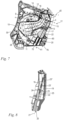
- Fig. 7 A section of the cooling air duct 10 is shown.
- the first ventilation grille 30 is shown in dashed lines. Accordingly, the cooling air flow 11 flows in the direction of the Fig. 7 through the channel inlet 26. Immediately after flowing through the first ventilation grille 30, the cooling air flow 11 changes its direction towards the rear end 34 of the housing 2. Due to the change in the flow direction of the cooling air flow 11, dirt particles, in particular mineral dirt particles, are thrown against a first longitudinal side 18 of the cooling air channel 10.
- a reservoir 33 for receiving dirt particles is formed on the longitudinal side 18 of the cooling air channel 10 in the area of the channel inlet 26.
- the reservoir 33 extends in the direction from the first longitudinal side 46 to the second longitudinal side 47. In other words, the reservoir 33 represents an indentation in the longitudinal side 18.
- a magnetic separator device 20 is arranged in the curved channel section 12 of the cooling air channel 10.
- the magnetic separator device 20 is thus arranged upstream of the drive motor 3.
- the magnetic separator device 20 serves to separate ferromagnetic particles from the cooling air flow 11.
- the magnetic separator device 20 comprises at least one permanent magnet 23, 23', 23".
- the Magnetic separator device 20 has several, in particular three permanent magnets 23, 23', 23". It can be expedient to provide a different number and a different size of the permanent magnets 23, 23', 23", in particular in an embodiment of the tool 1 according to the invention, which has a cooling air flow 11 with a significantly different volume flow.
- the magnetic separator device 20 comprises a carrier 22.
- the at least one permanent magnet 23, 23', 23", in particular the several, preferably the three permanent magnets 23, 23', 23", is held on the carrier 22.
- the carrier 22 has a base 70.
- a base 71 is formed on the base 70 of the carrier 22.
- the base 71 serves to rest on the housing 2 of the tool 1.
- a sword-shaped extension 72 is arranged on the end of the base 71 facing away from the base 70.
- the permanent magnets 23, 23', 23" are held on the extension 72.
- the magnetic separator device 20 has a longitudinal central axis 21.
- the base 70, the base 71 and the extension 72 are arranged one behind the other along the longitudinal central axis 21.
- the cross section of the extension 72 is smaller than the cross section of the base 71.
- the permanent magnets 23, 23', 23" are arranged one behind the other in the direction of the longitudinal central axis 21 of the magnetic separator device 20.
- the extension 72 has openings 74, 74', 74".
- a permanent magnet 23, 23', 23" is held in each opening 74, 74', 74".
- the openings 74, 74', 74" are not designed as through-openings in the present embodiment. Accordingly, the openings 74, 74', 74" are formed on the first side 24 of the extension 72.
- the second side 25 of the extension 72 is closed.
- the permanent magnets 23, 23', 23" are glued to the carrier 22, in particular held in the openings 74, 74', 74" of the extension 72.
- the permanent magnets 23, 23', 23" are glued to one pole side.
- the permanent magnets 23, 23', 23" are pressed in.
- the permanent magnets 23, 23', 23" can advantageously be glued and pressed in.
- Other types of fastening of the permanent magnets 23, 23', 23" to the carrier 22 are also possible.
- An accumulation of ferromagnetic particles is possible in the area of both pole sides of the permanent magnets 23, 23', 23".
- the openings 74, 74', 74" can be designed as through-openings, so that both pole sides of the permanent magnets 23, 23', 23" have direct contact with the cooling air flow 11.
- the magnetic separator device 20 is detachably held on the housing 2.
- the magnetic separator device 20 has a fastening means 73, by means of which the magnetic separator device 20 is fastened to the housing 2.
- the fastening means 73 is designed as a screw in the preferred embodiment.
- the magnetic separator device 20 is inserted into the housing 2 with its extension 72 leading.
- the magnetic separator device 20 is supported on the housing 2 via the base 71.
- the base 71 also has two guide rails 75 which are formed on opposite sides of the base 71.
- the guide rails 75 engage in counter contours formed on the housing 2. This simplifies the assembly of the magnetic separator device 20.
- the extension 72 of the carrier 22 projects into the curved channel section 12 with the permanent magnets 23, 23', 23" attached to the extension 72.
- the base 70 of the magnetic separator device 20 is flush with the outside of the housing 2.
- the curved channel section 12 has an inner side 16 and an outer side 17 in its channel interior 14 in the region of its curvature 15.
- the radius of the outer side 17 is larger than the radius of the inner side 16.
- the first longitudinal side 18 of the curved channel section 12 and a second longitudinal side 19 of the curved channel section 12 opposite the first longitudinal side 18 are connected to one another by the inner side 16 and the outer side 17.
- the magnetic separator device 20 is arranged adjacent to the outer side 17 of the curved channel section 12. Accordingly, a distance b between the magnetic separator device 20 and the outer wall 17 of the curved channel section 12 is less than a distance a between the magnetic separator device 20 and the inner wall 16 of the curved channel section 12.
- the distance b between the magnetic separator device 20 and the outer wall 17 is at most 50%, preferably at most 30%, preferably at most 15% of the distance a between the magnetic separator device 20 and the inner wall 16.
- An average length of the curved channel section 12 is preferably 100 to 140 mm.
- the cooling air flow 11 in the curved channel section 12 of the cooling air channel 10 has a main flow 13.
- the main flow 13 runs along the curved channel section 12.
- Centrifugal forces act on particles, in particular ferromagnetic particles, which are located in the main flow 13.
- the centrifugal forces acting on the particles carry them outwards, i.e. to the outside 17 of the curved section 12.
- the centrifugal forces acting on the particles also increase.
- the main flow 13 has a first flow plane 41 and a second flow plane 42.
- the main flow 13 is formed substantially perpendicular to the flow planes 41, 42.
- the flow planes 41, 42 intersect the main flow 13 at different flow sections of the main flow 13.
- the first flow plane 41 and the second flow plane 42 enclose an angle ⁇ .
- the angle ⁇ is open towards the magnetic separator device 20, in particular towards at least one permanent magnet 23, 23', 23".
- the angle ⁇ is preferably at least 10°, in particular at least 30°, particularly preferably at least 60°, in particular at least 80°.
- the magnetic separator device 20 is arranged in the curved channel section 12 in such a way that the ferromagnetic particles which are carried by the centrifugal force from the main flow 13 towards the outside 17 of the curved channel section 12 are captured by the permanent magnets 23, 23', 23".
- the ferromagnetic particles are separated by the Fig. 7
- the point cloud shown is shown schematically. In order to capture as many ferromagnetic particles as possible, it is advantageous if the Magnetic separator device 20 extends over as large a section as possible along the curved channel section 12, in particular along the section with the greatest curvature.
- the magnetic separator device 20 extends between the two flow planes 41, 42 over an angle ⁇ that is at least 10°, preferably at least 30°, particularly preferably at least 50°.
- the angle ⁇ results from a first tangential plane 76 and a second tangential plane 77, which intersect in the same straight line as the flow planes 41, 42.
- the first tangential plane 76 is tangent to the extension 72 of the magnetic separator device 20 at the end facing the base 71.
- the second tangential plane 77 is tangent to the extension 72 of the magnetic separator device 20 at the free end.
- the main flow 13 of the cooling air flow 11 first runs towards the magnetic separator device 20. Shortly before reaching the magnetic separator device 20, the main flow 13 runs along a curve and flows away from the magnetic separator device 20. In order for the ferromagnetic particles to also be thrown in the direction of the magnetic separator device 20, it is advantageous if the initial flow direction of the main flow, i.e. the flow direction of the main flow in the first flow plane 41, is directed towards the magnetic separator device 20.
- the magnetic separator device 20 thus overlaps with the direction of the main flow 13 at the first flow plane 41. Accordingly, an imaginary extension axis of the main flow 13 intersects the magnetic separator device 20 at the first flow plane 41.
- the magnetic separator device 20 is preferably located opposite to the direction of the main flow 13 in the second flow plane 42, overlapping with the main flow 13.
- An imaginary extension axis on the main flow 13 in the second flow plane 42 also intersects the magnetic separator device 20.
- the first flow plane 41 is located upstream of the second flow plane 42.
- the magnetic separator device 20 is arranged in the curved channel section 12 such that the longitudinal center axis 21 of the magnetic separator device 20 is aligned approximately tangentially to the main flow 13.
- the magnetic separator device 20 is arranged in the curved channel section 12 in such a way that the magnetic separator device 20 can be flowed around on its longitudinal sides 24, 25 in the area of the permanent magnets 23, 23', 23". Accordingly, the permanent magnets 23, 23', 23" are arranged at a distance from the longitudinal sides 18, 19 of the curved channel section 12.
- the magnetic separator device 20 is arranged in the curved channel section in such a way that the first longitudinal side 24 of the magnetic separator device 20 faces the first longitudinal side 18 of the curved channel section 12. Furthermore, the second longitudinal side 25 of the magnetic separator device 20 faces the second longitudinal side 19 of the curved channel section 12.
- a collection area 80 for collecting particles, in particular ferromagnetic particles, is provided in the curved channel section 12 in the area of the magnetic separator device 20.
- the collection area 80 is arranged below the main flow 13.
- the collection area 80 adjoins the base 71 of the magnetic separator device 20. If the magnetic separator device 20 is dismantled for cleaning, for example, all particles in the collection area 80 fall out of the cooling air channel 10 into the environment.
- the ventilation grille 30 has at least one inlet opening 31.
- the inlet openings 31 together form the duct inlet 26, via which the cooling air flow 11 flows into the channel interior 14.
- the inlet openings 31 are the openings provided between the individual ribs of the ventilation grille 30. If tools are used in humid environments, splash water can enter the cooling air channel 10 via the ventilation grille 30. This can also be the case, for example, if the tool 1 is sprayed with water for cleaning.
- a drainage opening 32 is provided on the ventilation grille 30.
- the drainage opening 32 is designed in such a way that water that has entered the cooling air channel 10 can drain out of the drainage opening 32 into the environment.
- the drainage opening 32 is formed by the lowest inlet opening 31 of the ventilation grille 30.
- the drainage opening 32 is designed in such a way that when the working device 1 ( Fig. 1 ), liquid contained in the cooling air channel 10 can completely drain off in the region of the channel inlet 26.
- the drainage opening 32 is arranged at least as deep as the floor of the channel interior 14 in the region of the channel inlet 26.
- the drainage opening 32 has a drainage slope directed towards the environment so that liquids can drain even better from the channel interior 14 into the environment.
- the angle ⁇ between the two flow planes 41, 42 is significantly larger, in particular over 90°.
- the magnetic separator device 20 is also located upstream of the electric motor. However, the cooling air flow 11 leads directly after the curved channel section 12 to the cooling body 58 at the Control unit 55.
- the openings 74, 74', 74" of the magnetic separator device 20 are designed as through-openings. Snap connections 78 are provided as fastening for the permanent magnets 23, 23', 23". The permanent magnets 23, 23', 23" are simply pressed into the openings 74, 74', 74" until they snap into place.
- the magnetic separator device 20 comprises a fixing element 81 for fixing the permanent magnets 23, 23', 23" in the carrier 22.
- an opening 74, 74', 74" for receiving the permanent magnets 23, 23', 23" is also formed in the carrier 22 for each permanent magnet 23, 23', 23".
- the opening 74, 74', 74" is designed as a through opening in the present case.
- the opening 74, 74', 74" can also be designed to be closed on one side.
- the carrier 22 has a support surface 82 in each opening 74, 74', 74", against which the permanent magnet 23, 23', 23" inserted into the opening 74, 74', 74" comes to rest.
- the support surface 82 is formed on the second longitudinal side 25 of the magnetic separator device 20.
- the permanent magnet 23, 23', 23" thus rests with its underside 84 on the support surface 82 of the second longitudinal side 25 of the magnetic separator device 20.
- the fixing element 81 is provided so that the permanent magnet 23, 23', 23" is held in the carrier 22.
- the permanent magnet 23, 23', 23" on the first longitudinal side 24 of the magnetic separator device 20 should thus be prevented from falling out.
- the fixing element 81 contacts the permanent magnet 23, 23', 23" on its upper side 85 opposite the underside 84 and thereby fixes it in the opening 74, 74', 74" of the magnetic separator device 20.
- the permanent magnet 23, 23', 23" from the opening 74, 74', 74" on the first longitudinal side 24 of the magnetic separator device 20 is therefore not possible.
- the permanent magnet 23, 23', 23" is held at its two end faces 86, 87 by positioning webs 83 in the direction of the longitudinal axis 21 of the magnetic separator device 20.
- at least two positioning webs 83 spaced apart from one another are provided on the carrier 22 for the first end face 86 of the permanent magnet 23, 23', 23".
- the positioning webs 83 each have an effective surface 89 with which they contact the first end face 86 of the permanent magnet 23, 23', 23".
- At least two positioning webs 83 are also provided for the second end face 87 of the permanent magnet 23, 23', 23", which contact the second end face 87 of the permanent magnet 23, 23', 23" with their effective surfaces 89.
- a two-point support is provided on both end faces 86, 87 of the permanent magnet 23, 23', 23", which enables the permanent magnet 23, 23', 23" to be firmly fixed in the carrier 22 in the direction of the longitudinal axis 21.
- Free spaces are provided between the individual positioning webs 83. These enable dirt particles to be collected and/or removed so that they do not become trapped when the permanent magnets 23, 23', 23" between the carrier 22 and the permanent magnet 23, 23', 23". This makes it possible to install the permanent magnets 23, 23', 23" easily and safely, even in dirty environments.
- the formation of the positioning webs 83 prevents material accumulations.
- the carrier 22 is preferably cast, in particular injection-molded.
- positioning webs 83 By avoiding such material accumulations by forming positioning webs 83, distortion during component manufacture can be avoided.
- the positioning webs 83 also serve to compensate for tolerances. If the permanent magnet 23, 23', 23" has to be pressed between the positioning webs 83 under pressure, the positioning webs 83 can be deformed better than with material accumulations.
- the permanent magnet 23, 23', 23 ⁇ ⁇ is fixed on its respective long side 88 via two spaced-apart side supports 90. Between the A free space is also formed between the side supports 90 so that the permanent magnet 23, 23', 23" is not contacted by the carrier 22 between the side supports 90. For the same reasons described above, a simple and safe installation of the permanent magnets 23, 23', 23" can thus be achieved even in dirty environments.
- the fixing element 81 is tongue-shaped.
- the fixing element 81 can be plugged onto the carrier 22 of the magnetic separator device 20. If the fixing element 81 is plugged onto the carrier 22, it covers the permanent magnets 23, 23', 23" at least partially, in particular completely on the first long side 24 of the magnetic separator device 20.
- the fixing element 81 is detachably fastened to the carrier 22.
- the fixing element 81 is held on the carrier 22 by a locking connection.
- the locking connection can be released by the operator so that the fixing element 81 can be released from the carrier again.
- other connections for fastening the fixing element 81 to the carrier 22 of the magnetic separator device 20 can also be expedient.
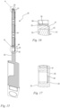
- the fixing element 81 extends from a first end 91 to a second end 92. At the first end 91, the fixing element 81 is cranked, the cranking being formed by a type of tab 93. At the second end 92, the fixing element 81 has an opening 94 which is provided for receiving a locking hook 95. The locking hook 95 is formed on the carrier 22.
- the permanent magnets 23, 23', 23" are to be inserted or pushed into the openings 74, 74', 74" provided for this purpose until their underside 84 abuts the support surface 82 of the carrier 22.
- the fixing element 81 is then pushed with its second end 92 forward into the carrier 22 in the direction of the longitudinal axis 21.
- a guide is formed on the first longitudinal side 24 of the carrier 22 or the magnetic separator device 20, in which the fixing element 81 slides into the carrier 22.
- the guide is formed by a plurality of tabs 96 arranged laterally on the carrier 22 and overlapping the fixing element 81.
- the fixing element 81 is held between the lateral tabs 96 and the positioning webs 83 when inserted into the carrier 22. As shown in the Figures 15 to 17 shown, the fixing element 81 is to be pushed into the carrier 22 until the tab 93 at the first end 91 of the fixing element 81 comes to rest on a stop 68 of the carrier 22.
- the locking hook 95 of the carrier 22 engages in the opening 94 of the fixing element 81 and fixes it in the carrier 22. The locking can be released again by lifting the locking hook 95 in order to pull the fixing element 81 out of the carrier 22 again.
- two further locking hooks 97 are formed on the carrier 22, which engage around the tab 93 and additionally hold the fixing element 81 in the guide ( Figures 13 and 14 ).
- the fixing device 81 is made of a non-ferromagnetic material in order not to weaken or cancel out the magnetic effect of the permanent magnets 23, 23', 23" by shielding or magnetic flux linkage.
- the fixing device 81 can be designed as a sheet metal.
- the fixing device 81 can also consist of a plastic.
Landscapes
- Engineering & Computer Science (AREA)
- Power Engineering (AREA)
- Mechanical Engineering (AREA)
- Motor Or Generator Cooling System (AREA)
Applications Claiming Priority (1)
| Application Number | Priority Date | Filing Date | Title |
|---|---|---|---|
| DE102023106399.5A DE102023106399A1 (de) | 2023-03-14 | 2023-03-14 | Elektrisches Arbeitsgerät |
Publications (1)
| Publication Number | Publication Date |
|---|---|
| EP4450231A1 true EP4450231A1 (fr) | 2024-10-23 |
Family
ID=90365373
Family Applications (1)
| Application Number | Title | Priority Date | Filing Date |
|---|---|---|---|
| EP24163324.7A Pending EP4450231A1 (fr) | 2023-03-14 | 2024-03-13 | Outil électrique |
Country Status (4)
| Country | Link |
|---|---|
| US (1) | US20240308108A1 (fr) |
| EP (1) | EP4450231A1 (fr) |
| CN (1) | CN118659589A (fr) |
| DE (1) | DE102023106399A1 (fr) |
Families Citing this family (1)
| Publication number | Priority date | Publication date | Assignee | Title |
|---|---|---|---|---|
| JP7704704B2 (ja) * | 2022-03-24 | 2025-07-08 | 株式会社やまびこ | 携帯型切断機 |
Citations (5)
| Publication number | Priority date | Publication date | Assignee | Title |
|---|---|---|---|---|
| DE3824234C2 (fr) * | 1988-07-16 | 1990-07-12 | Robert Bosch Gmbh, 7000 Stuttgart, De | |
| WO2008018611A1 (fr) * | 2006-08-11 | 2008-02-14 | Hitachi Koki Co., Ltd. | Machine-outil électrique |
| EP2095910A1 (fr) * | 2008-02-28 | 2009-09-02 | Metabowerke GmbH | Outil électro-manuel doté d'aimants destinés à absorber la poussière |
| KR101370035B1 (ko) * | 2013-09-05 | 2014-03-06 | 주식회사 아임삭 | 쇳가루 집진 구조를 갖는 휴대용 전동공구 |
| DE102015225748A1 (de) * | 2015-12-17 | 2017-06-22 | Robert Bosch Gmbh | Handwerkzeugmaschine mit einem Filterträger |
Family Cites Families (7)
| Publication number | Priority date | Publication date | Assignee | Title |
|---|---|---|---|---|
| DE963637C (de) * | 1953-05-14 | 1957-05-09 | Spodig Heinrich | Magnetfilterstab |
| DE1954476U (de) * | 1963-03-09 | 1967-02-02 | Heinrich Dipl Ing Spodig | Magnetfilterstab. |
| DE20304324U1 (de) * | 2003-03-17 | 2003-07-10 | Comfort Sinusverteiler GmbH, 48493 Wettringen | Hydraulische Weiche |
| AT510358B1 (de) * | 2010-09-10 | 2015-07-15 | Traktionssysteme Austria Gmbh | Permanentmagneterregte elektrische maschine |
| DE102015224791A1 (de) * | 2015-12-10 | 2017-02-02 | Robert Bosch Gmbh | Handwerkzeugmaschine mit einer Staubschutzvorrichtung |
| WO2021107827A1 (fr) * | 2019-11-25 | 2021-06-03 | Husqvarna Ab | Outil de travail portatif alimenté électriquement |
| EP4147824A4 (fr) * | 2020-06-15 | 2023-12-06 | Globe (Jiangsu) Co., Ltd. | Dispositif de coupe électrique |
-
2023
- 2023-03-14 DE DE102023106399.5A patent/DE102023106399A1/de active Pending
-
2024
- 2024-03-13 CN CN202410286132.9A patent/CN118659589A/zh active Pending
- 2024-03-13 EP EP24163324.7A patent/EP4450231A1/fr active Pending
- 2024-03-13 US US18/604,117 patent/US20240308108A1/en active Pending
Patent Citations (5)
| Publication number | Priority date | Publication date | Assignee | Title |
|---|---|---|---|---|
| DE3824234C2 (fr) * | 1988-07-16 | 1990-07-12 | Robert Bosch Gmbh, 7000 Stuttgart, De | |
| WO2008018611A1 (fr) * | 2006-08-11 | 2008-02-14 | Hitachi Koki Co., Ltd. | Machine-outil électrique |
| EP2095910A1 (fr) * | 2008-02-28 | 2009-09-02 | Metabowerke GmbH | Outil électro-manuel doté d'aimants destinés à absorber la poussière |
| KR101370035B1 (ko) * | 2013-09-05 | 2014-03-06 | 주식회사 아임삭 | 쇳가루 집진 구조를 갖는 휴대용 전동공구 |
| DE102015225748A1 (de) * | 2015-12-17 | 2017-06-22 | Robert Bosch Gmbh | Handwerkzeugmaschine mit einem Filterträger |
Also Published As
| Publication number | Publication date |
|---|---|
| US20240308108A1 (en) | 2024-09-19 |
| DE102023106399A1 (de) | 2024-09-19 |
| CN118659589A (zh) | 2024-09-17 |
Similar Documents
| Publication | Publication Date | Title |
|---|---|---|
| DE10036458B4 (de) | Staubfangvorrichtung für eine Kreissäge | |
| EP1939456B1 (fr) | Dispositif de passage d'air | |
| DE102004029220B4 (de) | Handwerkzeuggerät mit Staubabsaugmodul | |
| EP2431132B1 (fr) | Appareil de travail manuel | |
| DE102017001002A1 (de) | Elektrohandwerkzeug mit staubschutz-abdeckung | |
| EP4491339B1 (fr) | Scie à chaîne motorisée ou tronçonneuse | |
| DE202018105372U1 (de) | Vorrichtung zur Muldenabsaugung von auf einem Kochfeld erzeugter Abluft | |
| EP1661662B1 (fr) | Dispositif de séparation grossier pour des particules aspirées | |
| DE102010023829A1 (de) | Motorbetriebenes Werkzeug | |
| DE112015002274T5 (de) | Lüftungseinheit für Fahrzeug-Klimaanlage | |
| DE19734146A1 (de) | Luftzuführeinrichtung | |
| DE2750967B1 (de) | Vorrichtung zum Verbinden eines Antriebsmotors und einer Pumpe | |
| EP0189113A2 (fr) | Echangeur de chaleur | |
| EP3751145B1 (fr) | Dispositif de ventilateur | |
| DE102023106399A1 (de) | Elektrisches Arbeitsgerät | |
| DE102008003931A1 (de) | Abdeckung für einen Luftfilter, insbesondere für ein Kraftfahrzeug | |
| DE20000863U1 (de) | Kühlgerät | |
| EP3620721A1 (fr) | Dispositif d'aspiration de cuves de l'air extrait sur une plaque de cuisson | |
| EP3825065B1 (fr) | Appareil de travail fonctionnant sur accumulateur doté d'un conduit d'air de refroidissement | |
| EP1559359B1 (fr) | Aspirateur | |
| EP3222919B1 (fr) | Hotte aspirante comprenant un couvercle transparent et élément interne | |
| DE10245419B4 (de) | Gebläseanordnung | |
| DE102011006542A1 (de) | Staubfangvorrichtung | |
| DE9200134U1 (de) | Kühlgerät für Schaltschränke | |
| EP4230352B1 (fr) | Appareil de travail portatif |
Legal Events
| Date | Code | Title | Description |
|---|---|---|---|
| PUAI | Public reference made under article 153(3) epc to a published international application that has entered the european phase |
Free format text: ORIGINAL CODE: 0009012 |
|
| STAA | Information on the status of an ep patent application or granted ep patent |
Free format text: STATUS: THE APPLICATION HAS BEEN PUBLISHED |
|
| AK | Designated contracting states |
Kind code of ref document: A1 Designated state(s): AL AT BE BG CH CY CZ DE DK EE ES FI FR GB GR HR HU IE IS IT LI LT LU LV MC ME MK MT NL NO PL PT RO RS SE SI SK SM TR |
|
| STAA | Information on the status of an ep patent application or granted ep patent |
Free format text: STATUS: REQUEST FOR EXAMINATION WAS MADE |
|
| 17P | Request for examination filed |
Effective date: 20250423 |