EP4450331A1 - Véhicule avec dispositif de marchepied avant, notamment pour véhicule, actionné de manière transversale - Google Patents
Véhicule avec dispositif de marchepied avant, notamment pour véhicule, actionné de manière transversale Download PDFInfo
- Publication number
- EP4450331A1 EP4450331A1 EP24155174.6A EP24155174A EP4450331A1 EP 4450331 A1 EP4450331 A1 EP 4450331A1 EP 24155174 A EP24155174 A EP 24155174A EP 4450331 A1 EP4450331 A1 EP 4450331A1
- Authority
- EP
- European Patent Office
- Prior art keywords
- support structure
- vehicle
- front support
- rear support
- step arrangement
- Prior art date
- Legal status (The legal status is an assumption and is not a legal conclusion. Google has not performed a legal analysis and makes no representation as to the accuracy of the status listed.)
- Granted
Links
Images


Classifications
-
- B—PERFORMING OPERATIONS; TRANSPORTING
- B60—VEHICLES IN GENERAL
- B60R—VEHICLES, VEHICLE FITTINGS, OR VEHICLE PARTS, NOT OTHERWISE PROVIDED FOR
- B60R3/00—Arrangements of steps or ladders facilitating access to or on the vehicle, e.g. running-boards
- B60R3/02—Retractable steps or ladders, e.g. movable under shock
-
- B—PERFORMING OPERATIONS; TRANSPORTING
- B60—VEHICLES IN GENERAL
- B60R—VEHICLES, VEHICLE FITTINGS, OR VEHICLE PARTS, NOT OTHERWISE PROVIDED FOR
- B60R21/00—Arrangements or fittings on vehicles for protecting or preventing injuries to occupants or pedestrians in case of accidents or other traffic risks
- B60R21/34—Protecting non-occupants of a vehicle, e.g. pedestrians
Definitions
- the invention relates to a vehicle with a front-side step arrangement, in particular arranged off-center on the vehicle and/or in the region of an opening arranged in a bumper cover.
- the invention relates primarily to motor vehicles, in particular to taller motor vehicles with a height of more than 1.80 m, in particular more than 2.00 m, more than 2.20 m or more than 2.50 m.
- taller vehicles with a windshield that is arranged close to the front of the vehicle, in particular in the area of a maximum of 1.0 m away from the front of the vehicle. This is the case with many light commercial vehicles and recreational vehicles, such as camper vans.
- FMV Full Front Vehicles
- the easy access to the upper area of the windshield of a taller vehicle without additional tools is an advantage and desirable from the customer's point of view.
- step It is known from practice to provide a step or several steps on higher motor vehicles as described above, which enable a person to stand on this step with their body weight in order to reach the upper area of the windshield of the motor vehicle.
- the step is designed to be sufficiently rigid for this purpose.
- a cross member composed of several individual elements is known, which is designed as a deformation element for the purpose of pedestrian protection.
- the publication refers exclusively to the cross member itself and does not refer to a step arrangement on a motor vehicle.
- a vehicle front-end module which has a cross member and a lower pedestrian protection cross member extending in the vertical direction of the vehicle below the cross member.
- the lower pedestrian protection cross member is connected to the cross member via several connecting profiles extending in the vertical direction of the vehicle and in the longitudinal direction of the vehicle. No reference is made to a step arrangement.
- a step arrangement in a motor vehicle which is arranged at the front in a central vehicle area between an upper pedestrian protection cross member and a lower bumper cross member.
- the step plate is designed as a deformation element and is essentially made up of step segments arranged one behind the other, which are spaced apart from one another in the longitudinal direction of the vehicle by a deformation path.
- This step arrangement requires an installation space of the required height between the cross members. For this reason, the arrangement is not suitable for implementation in the outer vehicle areas viewed in the transverse direction of the vehicle in most motor vehicles.
- the invention is based on the object of providing a vehicle with a front-side step arrangement which can be implemented in the transverse direction of the vehicle in an outer vehicle area and/or within an opening formed in a bumper cover, in particular with only a small installation space requirement in the vertical direction of the vehicle.
- the step arrangement should also be advantageously designed with regard to pedestrian protection requirements, in particular in such a way that the step arrangement takes into account the provisions of "UN Regulation No. 127-02".
- a vehicle according to the invention with a front-side step arrangement has a front support structure viewed in the vehicle's longitudinal direction and a rear support structure arranged behind the front support structure in the vehicle's longitudinal direction, as well as at least one longitudinal extension element extending from the front support structure to the rear support structure.
- At least one of the elements is designed as a deformation structure in such a way that an impact force acting on the front support structure from the front in the vehicle's longitudinal direction causes a rotational or pivoting movement of the entire step arrangement and/or a relative movement between the front support structure and the rear support structure.
- the step arrangement is designed in such a way that, in the event of an impact force acting from the front, as occurs in particular in the case of a pedestrian impact, the entire step arrangement can move backwards out of the impact area by pivoting or twisting and/or the step arrangement is designed in such a way that a relative movement between the front support structure and the rear support structure is made possible and the support structure can thus move backwards by acting as a deformation element itself.
- the step arrangement is designed in such a way that, in the event of an impact force acting from the front, as occurs in particular in the case of a pedestrian impact, the entire step arrangement can move backwards out of the impact area by pivoting or twisting and/or the step arrangement is designed in such a way that a relative movement between the front support structure and the rear support structure is made possible and the support structure can thus move backwards by acting as a deformation element itself.
- the step arrangement of a vehicle according to the invention is designed such that an impact force acting from the front in the longitudinal direction of the vehicle through a test body on the front support structure causes a penetration depth of at least 60 mm at a force level of maximum 5 kN.
- At least two longitudinal struts extend from the front support structure to the rear support structure as longitudinal extension elements.
- more than two longitudinal struts are provided, in particular at least three, at least four, at least five, at least six or more longitudinal struts.
- the longitudinal extension element can also be designed to be flat if, by means of longitudinally arranged slots as previously described for individual longitudinal struts, only small cross-sectional areas of the longitudinal struts remaining in the element are realized, which are thus flexible for attachment to the front and/or rear support structure.
- a flat element can also be provided as the longitudinal extension element, which is designed in such a way that it has only a low shear stiffness.
- a lattice or honeycomb-like structure is designed in such a way that it has only a low shear stiffness.
- the at least one longitudinal extension element is arranged so as to be relatively movable relative to the front support structure and/or relatively movable relative to the rear support structure. This preferably applies to each longitudinal extension element if two or more longitudinal extension elements are provided.
- the front support structure can also be fixed in a relatively movable manner relative to another body element.
- a design is particularly suitable for forming a predetermined bending point or a pivoting arrangement of the front support structure or the rear support structure relative to another body element.
- a vertical support extending in the vertical direction of the vehicle and/or a bumper cross member extending in the transverse direction of the vehicle can serve as a further body element.
- the front support structure is preferably attached directly to such a vertical support or such a bumper cross member.
- the relative mobility can be achieved in particular by attaching the front support structure only on one side relative to the vertical support and/or relative to the bumper cross member.
- the relative mobility can be defined in particular by reducing the bending stiffness at a predetermined bending point, in particular by reducing the cross-sectional profile and/or by other design measures to reduce the bending stiffness.
- the front support structure and the rear support structure are brought together in a connecting area and are jointly fastened to another body element.
- the front support structure and the rear support structure are brought together in an area that is offset to the rear in the vehicle's longitudinal direction compared to the front support structure.
- a bulkhead plate is particularly suitable as a body element for fastening, which is arranged further back in the vehicle's longitudinal direction compared to a vehicle cross member. The distance between the bumper cross member and the bulkhead plate usually corresponds to the effective length of a deformation element arranged between them.
- the front support structure is attached directly or indirectly to a bumper cross member and/or the rear support structure is attached directly or indirectly to a bulkhead plate.
- a vehicle according to the invention can be implemented on a motor vehicle with relatively little design effort and little additional weight, since the bumper cross member and the bulkhead plate are already present in most vehicles as elements of a crash management system.
- the positioning of the step arrangement is off-center, particularly when viewed in the transverse direction of the vehicle, preferably on the outside of the deformation element of a crash management system.
- the bulkhead plate is usually a flat component with a thickness that is significantly less than the length and width.
- the bulkhead plate is usually arranged on the front side of a longitudinal member and protrudes radially outwards from the longitudinal member, usually in all directions.
- front support structure and the rear support structure are only fixed on one side, in particular on the inside of the vehicle when viewed in the transverse direction of the vehicle, a connection is created in which, in the event of an impact force acting on the front support structure from the front in the longitudinal direction of the vehicle, a rotational or pivoting movement is caused around the respective area in which the front support structure and the rear support structure are fixed on one side.
- the invention was made in particular for vehicles in which a step arrangement is to be provided within an opening formed in a bumper cover.
- the step arrangement is to be accessible by using the opening, for example by arranging the step arrangement in the area of the lower end of the opening in such a way that it can be used by inserting a foot into the opening and then placing it downwards on the step arrangement.
- the opening preferably extends off-center, viewed in the transverse direction of the vehicle, in an outer front area of the vehicle, in particular in the area of a right or left headlight and in the vertical direction of the vehicle below the respective headlight and/or on the outside of a centrally arranged radiator grille.
- the step arrangement can also be arranged inside the opening below the lower edge visible from the outside in such a way that a foot can enter the opening and dip slightly downwards in order to be placed on the step arrangement. Such an arrangement is also considered to be an arrangement inside the opening within the meaning of the invention.
- a predetermined breaking point is formed on the front support structure and/or a predetermined bending point or a swivel joint is formed on the rear support structure.
- a design as described above can also be implemented in reverse.
- a predetermined bending point or a swivel joint is formed on the front support structure and/or a predetermined breaking point is formed on the rear support structure.
- the predetermined bending point or the swivel joint serves as the central axis of rotation for the entire step arrangement.
- a low shear stiffness can cause the longitudinal extension element to collapse in order to absorb further deformation energy via the step arrangement.
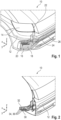
- FIGS. 1 and 2 show an isometric representation of a vehicle front end 10 with a front bumper cover 12, which extends essentially over the entire vehicle width extending in the vehicle transverse direction (y-direction).
- a headlight 14 is arranged above the bumper cover 12.
- an opening 16 is formed below the headlight 14 in the bumper cover 12, in which an insert element 18 is arranged.
- Figure 1 In Figure 1 is shown in dashed lines a step arrangement 20 which, viewed in the transverse direction of the vehicle, is attached to an arrangement of a bulkhead plate 22, a deformation element 24 and a bumper cross member 26.
- a step arrangement 20 which, viewed in the transverse direction of the vehicle, is attached to an arrangement of a bulkhead plate 22, a deformation element 24 and a bumper cross member 26.
- step arrangement 20 is located within the opening 16 in the vehicle longitudinal direction behind the bumper cover 12.
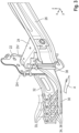
- the step arrangement 20 comprises a front support structure 30, a rear support structure 32 and a plurality of longitudinal extension elements 34 in the form of longitudinal struts 36 extending in the vehicle's longitudinal direction from the front support structure 30 to the rear support structure 32.
- the vertical support 38 leads upwards in the vertical direction of the vehicle (z-direction) to an upper cross member (not shown) which extends parallel to the bumper cross member 26.
- This upper cross member (not shown) above the bumper cross member 26 is also referred to as an upper pedestrian protection cross member.
- the upper cross member (not shown) is not required to implement the invention. This is also apparent in particular from the wording of claim 1, which does not refer to an upper cross member.
- the rear support structure 32 is connected to the bulkhead plate 22.
- the bulkhead plate 22 is in turn connected to the bumper cross member 26 via the deformation element 24.
- the bumper cross member 26, the deformation element 24, the bulkhead plate 22 and a longitudinal member (not shown) adjoining behind the bulkhead plate 22 form a crash management system of the motor vehicle.
- the step arrangement 20 is thus formed on the outside of the crash management system as an extension of the bulkhead plate 22 and the bumper cross member 26.
- the front support structure 30 forms an external extension of the bumper cross member 26, wherein the front support structure 30 is offset relative to the bumper cross member 26 by the Depth of the vertical support 38 is offset.
- the rear support structure 32 forms an external extension of the bulkhead plate 22.
- the longitudinal struts 36 are arranged in an articulated manner relative to the rear support structure 32, which is visualized by the axes of rotation marked with arrows and a line DL. Furthermore, the connection areas of the front support structure 30 and the rear support structure 32 are functionally designed like a swivel joint, which is visualized by the line DV for the front support structure 30 and the line DH for the rear support structure 32.
- front support structure 30 has come closer to the rear support structure 32 by changing the angle of the longitudinal struts 36 by twisting them relative to the front support structure 30 and the rear support structure 32.
- step arrangement 20 In the Figures 6 to 9 Further embodiments of step arrangement 20 are shown, wherein identical or at least functionally equivalent elements are given the same reference numerals as in the Figures 1 to 5 be used.
- the front support structure 30 and the rear support structure 32 are brought together so that only one axis of rotation around the line DH is produced. Furthermore, only one longitudinal extension element 34 is provided between the front support structure 30 and the rear support structure 32, which has several elongated holes 42 extending in the vehicle's longitudinal direction (longitudinal direction). As a result, the longitudinal extension element 34 has a reduced shear stiffness and makes it possible to If the rear support structure 32 strikes another body element and a sufficiently large force acts on the front support structure 30 in the longitudinal direction of the vehicle from front to rear, the longitudinal extension element 34 collapses analogously to the Figures 1 to 5 described embodiment.
- the in Figure 7 The embodiment shown essentially corresponds to that in Figure 6 shown embodiment with the difference that the front support structure 30 is connected to the bumper cross member 26 via an element designed as a stretching element 50.
- the stretching element 50 can also be part of a Figure 7 vertical beam not shown, as shown in the Figures 1 to 5 shown and described in outline.
- the stretching element 50 has a large number of folds and is designed so that the front support structure 30 can be displaced in the longitudinal direction according to the arrow 44 even with a relatively low force, in that the unfolded stretching element 50 lengthens and unfolds. In this way, the front support structure 30 can be pushed forward on the inside in the direction of the rear support structure 32 and thus brought closer to the rear support structure 32 without the connection to the bumper cross member 26 being broken.
- a torsion spring, an angle plate or another elastically or plastically prestressed element can also be arranged, which enables a relative displacement of the front support structure 30 in the direction of the rear support structure 32.
- a torsion spring, an angle plate or another elastically or plastically prestressed element can also be arranged, which enables a relative displacement of the front support structure 30 in the direction of the rear support structure 32.
- FIG. 1 The arrangement shown in FIG. 1 is supplemented by an angle plate which is arranged and designed between the vertical support 38 and the bumper cross member 26 in such a way that it stretches plastically from front to rear when a force is applied in the longitudinal direction of the vehicle and in this respect behaves similarly to the Figure 7 shown stretching element 50.
- Such an angle plate (not shown) is significantly less expensive to manufacture, since it is structurally simpler.
- the angle plate can in particular have a design with a contact surface oriented in the transverse direction and in the vertical direction of the vehicle to the vertical support 38 and a connecting surface extending forwards in the vertical direction and in the longitudinal direction of the vehicle, by means of which a distance in the longitudinal direction of the vehicle is created between the vertical support 38 and the bumper cross member 26.
- a predetermined breaking point 46 is provided on the inside of the front support structure 30, ie in the area of the end of the front support structure 30 directed towards the bumper cross member 26, and on the inside of the rear support structure 32, ie in the area of the end of the rear support structure 32 directed towards the bulkhead plate 22, a predetermined bending point 48 is provided.
- the predetermined breaking point 46 is achieved by tapering the material and can additionally be supplemented by weakening the material, in particular by perforating it in the vertical direction (z-direction).
- the predetermined bending point 48 can in particular be achieved by suitable deformation, which causes bending or buckling at the corresponding point when loaded.
- a predetermined bending point 48 is provided on the inside of the front support structure and a predetermined breaking point 46 is provided on the inside of the rear support structure 32.
- the predetermined breaking point 46 and the predetermined bending point 48 can be created as described above.
- a recess 52 is provided on the top.
Landscapes
- Engineering & Computer Science (AREA)
- Mechanical Engineering (AREA)
- Body Structure For Vehicles (AREA)
Applications Claiming Priority (1)
| Application Number | Priority Date | Filing Date | Title |
|---|---|---|---|
| DE102023203597.9A DE102023203597A1 (de) | 2023-04-19 | 2023-04-19 | Fahrzeug mit frontseitiger Trittstufen-Anordnung, insbesondere in Fahrzeugquerrichtung betrachtet außermittig |
Publications (2)
| Publication Number | Publication Date |
|---|---|
| EP4450331A1 true EP4450331A1 (fr) | 2024-10-23 |
| EP4450331B1 EP4450331B1 (fr) | 2026-04-08 |
Family
ID=89834437
Family Applications (1)
| Application Number | Title | Priority Date | Filing Date |
|---|---|---|---|
| EP24155174.6A Active EP4450331B1 (fr) | 2023-04-19 | 2024-02-01 | Véhicule avec dispositif de marchepied avant, notamment pour véhicule, actionné de manière transversale |
Country Status (2)
| Country | Link |
|---|---|
| EP (1) | EP4450331B1 (fr) |
| DE (1) | DE102023203597A1 (fr) |
Citations (4)
| Publication number | Priority date | Publication date | Assignee | Title |
|---|---|---|---|---|
| US6634702B1 (en) | 1999-06-23 | 2003-10-21 | Dynamit Nobel Kunstsoff Gmbh | Front-end module for a motor vehicle |
| EP1884416B1 (fr) | 2006-08-01 | 2011-08-10 | Peugeot Citroën Automobiles S.A. | Cadre de bloc avant de véhicule automobile |
| DE102015221767A1 (de) | 2015-11-05 | 2017-05-11 | Volkswagen Aktiengesellschaft | Trittstufen-Anordnung in einem Kraftfahrzeug |
| CN211139245U (zh) | 2019-11-06 | 2020-07-31 | 爱达克车辆设计(上海)有限公司 | 一种汽车柔性小腿碰撞支撑结构及汽车 |
-
2023
- 2023-04-19 DE DE102023203597.9A patent/DE102023203597A1/de active Pending
-
2024
- 2024-02-01 EP EP24155174.6A patent/EP4450331B1/fr active Active
Patent Citations (4)
| Publication number | Priority date | Publication date | Assignee | Title |
|---|---|---|---|---|
| US6634702B1 (en) | 1999-06-23 | 2003-10-21 | Dynamit Nobel Kunstsoff Gmbh | Front-end module for a motor vehicle |
| EP1884416B1 (fr) | 2006-08-01 | 2011-08-10 | Peugeot Citroën Automobiles S.A. | Cadre de bloc avant de véhicule automobile |
| DE102015221767A1 (de) | 2015-11-05 | 2017-05-11 | Volkswagen Aktiengesellschaft | Trittstufen-Anordnung in einem Kraftfahrzeug |
| CN211139245U (zh) | 2019-11-06 | 2020-07-31 | 爱达克车辆设计(上海)有限公司 | 一种汽车柔性小腿碰撞支撑结构及汽车 |
Also Published As
| Publication number | Publication date |
|---|---|
| EP4450331B1 (fr) | 2026-04-08 |
| DE102023203597A1 (de) | 2024-10-24 |
Similar Documents
| Publication | Publication Date | Title |
|---|---|---|
| EP3668777B1 (fr) | Arrangement de longeron pour véhicule | |
| DE602005004913T2 (de) | Anordnung für eine fahrzeugseitenverkleidung und fahrzeug mit einer solchen seitenverkleidung | |
| DE2845548C2 (fr) | ||
| DE2426050A1 (de) | Selbsttragende fahrzeugkarosserie | |
| DE102007042292A1 (de) | Plastisch verformbare Doppelzellenverbindung für die Front von Automobilen | |
| DE2313588A1 (de) | Bodenrahmen fuer kraftfahrzeuge | |
| EP1503932B1 (fr) | Systeme d'attache pour cabine de conduite | |
| DE102011107995A1 (de) | Anstoßkraft absorbierendes Bauteil an einem Fahrzeug | |
| WO2007017198A1 (fr) | Vehicule a moteur dote d'une carrosserie presentant une structure de plancher, et d'au moins un element de renforcement pour le renfort de ladite structure de plancher | |
| DE602004009770T2 (de) | Stoßfängersystem | |
| EP1306290B1 (fr) | Structure avant de véhicule | |
| DE2353632C3 (de) | Halterung für die Armaturentafel und die Lenksäule in Kraftfahrzeugen | |
| EP3517328B1 (fr) | Attelage de remorque | |
| DE10222988B4 (de) | Einrichtung zum Schutz der Frontinsassen eines Cabrioletfahrzeuges | |
| DE102017011968B4 (de) | Vorrichtung zum Schutz von Batteriemodulen in einem Kraftfahrzeug | |
| DE10028704A1 (de) | Kraftfahrzeug mit Aggregateabsenkung | |
| DE4304920B4 (de) | Vorderwagen für ein Kraftfahrzeug | |
| DE60132988T2 (de) | Motorhaubenvorrichtung | |
| DE19835527B4 (de) | Schutzvorrichtung für Kraftfahrzeuge | |
| EP4450331B1 (fr) | Véhicule avec dispositif de marchepied avant, notamment pour véhicule, actionné de manière transversale | |
| DE102009035775A1 (de) | Kraftfahrzeug mit einem Deformationsbauteil | |
| DE102011113474B4 (de) | Stoßfänger | |
| DE102009007267A1 (de) | Anordnung eines Fangelements | |
| DE102014220703B4 (de) | Anordnung im Bereich eines Montageträgers im Vorderwagen eines Kraftfahrzeuges | |
| EP1457393A1 (fr) | Véhicule automobile avec protection pour des piétons |
Legal Events
| Date | Code | Title | Description |
|---|---|---|---|
| PUAI | Public reference made under article 153(3) epc to a published international application that has entered the european phase |
Free format text: ORIGINAL CODE: 0009012 |
|
| STAA | Information on the status of an ep patent application or granted ep patent |
Free format text: STATUS: THE APPLICATION HAS BEEN PUBLISHED |
|
| AK | Designated contracting states |
Kind code of ref document: A1 Designated state(s): AL AT BE BG CH CY CZ DE DK EE ES FI FR GB GR HR HU IE IS IT LI LT LU LV MC ME MK MT NL NO PL PT RO RS SE SI SK SM TR |
|
| STAA | Information on the status of an ep patent application or granted ep patent |
Free format text: STATUS: REQUEST FOR EXAMINATION WAS MADE |
|
| 17P | Request for examination filed |
Effective date: 20250423 |
|
| RIC1 | Information provided on ipc code assigned before grant |
Ipc: B60R 3/02 20060101AFI20250722BHEP Ipc: B60R 21/34 20110101ALI20250722BHEP |
|
| GRAP | Despatch of communication of intention to grant a patent |
Free format text: ORIGINAL CODE: EPIDOSNIGR1 |
|
| STAA | Information on the status of an ep patent application or granted ep patent |
Free format text: STATUS: GRANT OF PATENT IS INTENDED |
|
| INTG | Intention to grant announced |
Effective date: 20250925 |
|
| GRAS | Grant fee paid |
Free format text: ORIGINAL CODE: EPIDOSNIGR3 |
|
| P01 | Opt-out of the competence of the unified patent court (upc) registered |
Free format text: CASE NUMBER: UPC_APP_0018080_4450331/2025 Effective date: 20251217 |
|
| GRAA | (expected) grant |
Free format text: ORIGINAL CODE: 0009210 |
|
| STAA | Information on the status of an ep patent application or granted ep patent |
Free format text: STATUS: THE PATENT HAS BEEN GRANTED |
|
| AK | Designated contracting states |
Kind code of ref document: B1 Designated state(s): AL AT BE BG CH CY CZ DE DK EE ES FI FR GB GR HR HU IE IS IT LI LT LU LV MC ME MK MT NL NO PL PT RO RS SE SI SK SM TR |
|
| REG | Reference to a national code |
Ref country code: CH Ref legal event code: F10 Free format text: ST27 STATUS EVENT CODE: U-0-0-F10-F00 (AS PROVIDED BY THE NATIONAL OFFICE) Effective date: 20260408 Ref country code: GB Ref legal event code: FG4D Free format text: NOT ENGLISH |
|
| REG | Reference to a national code |
Ref country code: DE Ref legal event code: R096 Ref document number: 502024000983 Country of ref document: DE |