EP4450681A2 - Elektrolytische beschichtung für aluminiumbauteile mit schweissverbindungen - Google Patents
Elektrolytische beschichtung für aluminiumbauteile mit schweissverbindungen Download PDFInfo
- Publication number
- EP4450681A2 EP4450681A2 EP24159072.8A EP24159072A EP4450681A2 EP 4450681 A2 EP4450681 A2 EP 4450681A2 EP 24159072 A EP24159072 A EP 24159072A EP 4450681 A2 EP4450681 A2 EP 4450681A2
- Authority
- EP
- European Patent Office
- Prior art keywords
- component
- weld joint
- metallic body
- segments
- coating
- Prior art date
- Legal status (The legal status is an assumption and is not a legal conclusion. Google has not performed a legal analysis and makes no representation as to the accuracy of the status listed.)
- Pending
Links
Images


Classifications
-
- C—CHEMISTRY; METALLURGY
- C25—ELECTROLYTIC OR ELECTROPHORETIC PROCESSES; APPARATUS THEREFOR
- C25D—PROCESSES FOR THE ELECTROLYTIC OR ELECTROPHORETIC PRODUCTION OF COATINGS; ELECTROFORMING; APPARATUS THEREFOR
- C25D13/00—Electrophoretic coating characterised by the process
- C25D13/04—Electrophoretic coating characterised by the process with organic material
-
- F—MECHANICAL ENGINEERING; LIGHTING; HEATING; WEAPONS; BLASTING
- F16—ENGINEERING ELEMENTS AND UNITS; GENERAL MEASURES FOR PRODUCING AND MAINTAINING EFFECTIVE FUNCTIONING OF MACHINES OR INSTALLATIONS; THERMAL INSULATION IN GENERAL
- F16L—PIPES; JOINTS OR FITTINGS FOR PIPES; SUPPORTS FOR PIPES, CABLES OR PROTECTIVE TUBING; MEANS FOR THERMAL INSULATION IN GENERAL
- F16L58/00—Protection of pipes or pipe fittings against corrosion or incrustation
- F16L58/02—Protection of pipes or pipe fittings against corrosion or incrustation by means of internal or external coatings
- F16L58/04—Coatings characterised by the materials used
- F16L58/08—Coatings characterised by the materials used by metal
-
- C—CHEMISTRY; METALLURGY
- C25—ELECTROLYTIC OR ELECTROPHORETIC PROCESSES; APPARATUS THEREFOR
- C25D—PROCESSES FOR THE ELECTROLYTIC OR ELECTROPHORETIC PRODUCTION OF COATINGS; ELECTROFORMING; APPARATUS THEREFOR
- C25D13/00—Electrophoretic coating characterised by the process
- C25D13/12—Electrophoretic coating characterised by the process characterised by the article coated
- C25D13/14—Tubes; Rings; Hollow bodies
-
- C—CHEMISTRY; METALLURGY
- C25—ELECTROLYTIC OR ELECTROPHORETIC PROCESSES; APPARATUS THEREFOR
- C25D—PROCESSES FOR THE ELECTROLYTIC OR ELECTROPHORETIC PRODUCTION OF COATINGS; ELECTROFORMING; APPARATUS THEREFOR
- C25D5/00—Electroplating characterised by the process; Pretreatment or after-treatment of workpieces
- C25D5/34—Pretreatment of metallic surfaces to be electroplated
- C25D5/42—Pretreatment of metallic surfaces to be electroplated of light metals
- C25D5/44—Aluminium
-
- C—CHEMISTRY; METALLURGY
- C25—ELECTROLYTIC OR ELECTROPHORETIC PROCESSES; APPARATUS THEREFOR
- C25D—PROCESSES FOR THE ELECTROLYTIC OR ELECTROPHORETIC PRODUCTION OF COATINGS; ELECTROFORMING; APPARATUS THEREFOR
- C25D5/00—Electroplating characterised by the process; Pretreatment or after-treatment of workpieces
- C25D5/48—After-treatment of electroplated surfaces
-
- C—CHEMISTRY; METALLURGY
- C25—ELECTROLYTIC OR ELECTROPHORETIC PROCESSES; APPARATUS THEREFOR
- C25D—PROCESSES FOR THE ELECTROLYTIC OR ELECTROPHORETIC PRODUCTION OF COATINGS; ELECTROFORMING; APPARATUS THEREFOR
- C25D7/00—Electroplating characterised by the article coated
- C25D7/04—Tubes; Rings; Hollow bodies
-
- C—CHEMISTRY; METALLURGY
- C25—ELECTROLYTIC OR ELECTROPHORETIC PROCESSES; APPARATUS THEREFOR
- C25D—PROCESSES FOR THE ELECTROLYTIC OR ELECTROPHORETIC PRODUCTION OF COATINGS; ELECTROFORMING; APPARATUS THEREFOR
- C25D9/00—Electrolytic coating other than with metals
- C25D9/02—Electrolytic coating other than with metals with organic materials
-
- F—MECHANICAL ENGINEERING; LIGHTING; HEATING; WEAPONS; BLASTING
- F16—ENGINEERING ELEMENTS AND UNITS; GENERAL MEASURES FOR PRODUCING AND MAINTAINING EFFECTIVE FUNCTIONING OF MACHINES OR INSTALLATIONS; THERMAL INSULATION IN GENERAL
- F16L—PIPES; JOINTS OR FITTINGS FOR PIPES; SUPPORTS FOR PIPES, CABLES OR PROTECTIVE TUBING; MEANS FOR THERMAL INSULATION IN GENERAL
- F16L13/00—Non-disconnectable pipe joints, e.g. soldered, adhesive, or caulked joints
- F16L13/02—Welded joints
-
- F—MECHANICAL ENGINEERING; LIGHTING; HEATING; WEAPONS; BLASTING
- F16—ENGINEERING ELEMENTS AND UNITS; GENERAL MEASURES FOR PRODUCING AND MAINTAINING EFFECTIVE FUNCTIONING OF MACHINES OR INSTALLATIONS; THERMAL INSULATION IN GENERAL
- F16L—PIPES; JOINTS OR FITTINGS FOR PIPES; SUPPORTS FOR PIPES, CABLES OR PROTECTIVE TUBING; MEANS FOR THERMAL INSULATION IN GENERAL
- F16L58/00—Protection of pipes or pipe fittings against corrosion or incrustation
- F16L58/02—Protection of pipes or pipe fittings against corrosion or incrustation by means of internal or external coatings
- F16L58/04—Coatings characterised by the materials used
- F16L58/10—Coatings characterised by the materials used by rubber or plastics
-
- F—MECHANICAL ENGINEERING; LIGHTING; HEATING; WEAPONS; BLASTING
- F16—ENGINEERING ELEMENTS AND UNITS; GENERAL MEASURES FOR PRODUCING AND MAINTAINING EFFECTIVE FUNCTIONING OF MACHINES OR INSTALLATIONS; THERMAL INSULATION IN GENERAL
- F16L—PIPES; JOINTS OR FITTINGS FOR PIPES; SUPPORTS FOR PIPES, CABLES OR PROTECTIVE TUBING; MEANS FOR THERMAL INSULATION IN GENERAL
- F16L58/00—Protection of pipes or pipe fittings against corrosion or incrustation
- F16L58/18—Protection of pipes or pipe fittings against corrosion or incrustation specially adapted for pipe fittings
- F16L58/181—Protection of pipes or pipe fittings against corrosion or incrustation specially adapted for pipe fittings for non-disconnectable pipe joints
-
- F—MECHANICAL ENGINEERING; LIGHTING; HEATING; WEAPONS; BLASTING
- F16—ENGINEERING ELEMENTS AND UNITS; GENERAL MEASURES FOR PRODUCING AND MAINTAINING EFFECTIVE FUNCTIONING OF MACHINES OR INSTALLATIONS; THERMAL INSULATION IN GENERAL
- F16L—PIPES; JOINTS OR FITTINGS FOR PIPES; SUPPORTS FOR PIPES, CABLES OR PROTECTIVE TUBING; MEANS FOR THERMAL INSULATION IN GENERAL
- F16L9/00—Rigid pipes
- F16L9/02—Rigid pipes of metal
Definitions
- the present disclosure relates generally to protective coatings for metal substrates and, more particularly, an epoxy coating and the application thereof.
- Aluminum and aluminum alloy components used in aeronautics and aerospace applications are subjected to environments that cause corrosion. Such components have traditionally been anodized or conversion coated using chromic acid or anodized using sulfuric acid. Hexavalent chromium is heavily regulated by environmental agencies, and is banned in many countries, while either acid can be difficult to rinse away from certain components after processing, leading to cosmetic defects and/or corrosion. Thus, a need exists for improved coatings.
- a coated component includes a metallic body defining an inner volume configured to retain a fluid therein.
- the metallic body includes a plurality of segments, at least one weld joint attaching the plurality of segments, an outer surface, and an inner surface facing and defining the inner volume.
- the component further includes a chrome-free protective coating disposed on each of the outer surface and the inner surface.
- the coating includes an epoxy layer, and an oxide layer disposed between the epoxy layer and the respective outer surface and inner surface.
- a coated component includes a metallic body defining an inner volume configured to retain a fluid therein.
- the metallic body includes a bracket, a weld joint attaching the bracket to the metallic body, an outer surface, and an inner surface facing and defining the inner volume.
- the component further includes a chrome-free protective coating disposed on each of the outer surface and the inner surface.
- the coating includes an epoxy layer, and an oxide layer disposed between the epoxy layer and the respective outer surface and inner surface.
- a method of electrodepositing a protective coating on an aluminum component comprising at least one weld joint includes immersing the component in an electrodeposition bath, configuring the component as a positively-charged anode, applying voltage across the component to allow for deposition of the protective coating to form a coated component, rinsing the coated component, and curing the coated component.
- This disclosure presents an electrolytic chrome-free protective coating for welded aluminum components (i.e., those having weld joints).
- the coating is an electrodeposited anodic epoxy coating that includes a thin oxide layer for increased corrosion resistance, as well as adhesion of the subsequent organic coating.
- the coating is more environmentally friendly than chrome-based coatings and does not interact negatively with weld joints by way of electrolyte entrapment in crevices.
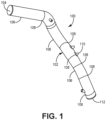
- FIG. 1 is a perspective view of duct 100 suitable for retaining and/or transporting fluids (e.g., gases or liquids) within a larger fluid handling system.
- duct 100 can be a gas-carrying duct as part of a bleed-air or environmental control system (ECS) of an aircraft.
- ECS environmental control system
- Duct 100 includes hollow metallic body 102 defining internal volume 104 within which fluid can be passed.
- body 102 can be formed from aluminum (including aluminum alloys).
- Body 102 can be composed of multiple smaller segments 106 (not all are labeled in FIG. 1 ) attached by weld joints 108 (not all are labeled in FIG. 1 ).
- segments 106 are hollow/tubular structures, so weld joints 108 fully circumscribe body 102 in order to fluidly seal body 102. Welding together smaller segments 106 allows for the formation of an elongate body 102 with precisely positioned straight and curved portions, as can be desirable in tight spaces (e.g., small compartments, bulkheads, etc.).
- Duct 100 further includes external features 110, which in the embodiment shown, are bosses (hereinafter "bosses 110"). Bosses 110 can also be connected to body 102 via weld joints 108. Bosses 110 can interconnect duct 100 to various mounting and/or support structures of the aircraft.
- Duct 100 can further include flanged ends 112, which can also be connected to body 102 by weld joints 108. Flanged ends 112 can help mate duct 100 to other ducts and/or components.
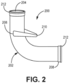
- FIG. 2 is a perspective view of duct 200, also suitable for carrying fluids.
- Duct 200 is similar to duct 100 in that it includes hollow body 202, preferably formed from aluminum, defining internal volume 204. Accordingly, duct 200 may be part of the same fluid handling system as duct 100, or a different system. Hollow body 202 is curved such that fluid passing therethrough turns roughly 90°.
- Duct 200 includes external feature 210, which in the embodiment shown is a bracket (hereinafter "bracket 210"). Bracket 210 can also be formed from aluminum or other metal and attached to body 202 by weld joint 208.
- Duct 200 can further include flanged ends 212, each attached via a weld joint 208, for interfacing duct 200 to another duct (e.g., duct 100) and/or component.
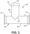
- FIG. 3 is a perspective view of duct 300, also suitable for carrying fluids.
- Duct 300 is similar to ducts 100 and 200 in that it includes hollow body 302, preferably formed from aluminum, defining internal volume 304 (indicated with a dashed lead line).
- Duct 300 is a tee for transitioning fluid flow 90° and includes orthogonally disposed straight segments 306.
- Duct 300 can alternatively be used to introduce a first fluid flow traveling at a first direction into a second fluid flow traveling at a second, orthogonal direction.
- Angled weld joint 308 attaches one segment 306 to the other. Weld joint 308 is referred to as angled because it is disposed at an angle relative to segments 306.
- Duct 300 can also include flanged ends 312, each attached via (circumferential) weld joint 308, for interfacing duct 300 to another duct (e.g., duct 100 and/or duct 200) and/or component.
- Ducts 100, 200, and/or 300 can ideally include a protective (e.g., corrosion resistant) coating.
- a protective coating e.g., corrosion resistant
- FIG. 4 illustrates steps 416 to 424 of method 414 for electrodepositing a protective coating on a welded aluminum component to form a coated component.
- electrodeposition and “electrodepositing” refer to anodic deposition.
- FIG. 5 is a simplified cross-sectional illustration of tubular coated component 500. FIGS. 4 and 5 are discussed together.
- Coated component 500 can be a duct substantially similar to any of ducts 100, 200, or 300.
- Coated component 500 includes body 502 formed from segments 506 attached at weld joint 508.
- Body 502 defines internal volume 504 through which fluid can pass.
- weld joint 508 extends generally orthogonally between respective outer and inner surfaces 524 and 526.
- body 502 can undergo optional preparation of surfaces 524 and 526, such as degreasing, rising, deoxidation, and further rinsing.
- Each sub-step can be carried out by immersing component 500 in a bath of the appropriate solution. Such surface preparation can facilitate the subsequent electrodeposition step.
- protective coating 528 can be electrodeposited on body 502, and more specifically, surfaces 524 and 526.
- Coating 528 can be a chrome-free water-based epoxy coating (or primer) in an exemplary embodiment.
- Body 502 is immersed in an electrocoat bath and positively charged, such that body 502 is the anode.
- coating 528 can be an anodic coating.
- Coating 528 deposits relatively uniformly on each of outer and inner surfaces 524 and 526, respectively. In some cases, coating 528 can be slightly thinner on inner surface 526 relative to its thickness on outer surface 524. Coating 528 is generally coextensive with the areas of respective outer and inner surfaces 524 and 526, as body 502 is fully immersed in the electroplating bath.
- Coating 528 can be controlled by one or a combination of immersion time and applied voltage.
- Coating 528 includes epoxy layer 530 and relatively thin oxide (e.g., Al 2 O 3 ) layer 532 formed initially during electrodeposition.
- Oxide layer 532 can be a dense layer of oxide filaments. Oxide layer 532 can anchor epoxy layer 530 to the underlying aluminum, and thus imparts greater corrosion resistance to surfaces 524 and 526 than epoxy layer 530 alone.
- the now coated component 500 can be rinsed at step 420.
- Rinsing can include the immersion of component 500 in one or more vats of a rinsing solution.
- component 500 can be placed into an oven to cure coating 528 at a temperature ranging from 100°C to about 120°C.
- additional coatings such as a topcoat, can be applied over cured coating 528.
- Coating 528 and method 414 have many benefits.
- coating 528 does not involve corrosive materials that can become trapped within weld joints which may lead to discoloration and/or corrosion of a component.
- Electrodeposition is more controlled than, for example, spray coating techniques, such that coating 528 can be more uniformly applied, and in less time. This includes more uniform deposition on inner surfaces of complexly-shaped components.
- Coating 528 and method 414 are also environmentally friendly. Coating 528 is chrome-free, low VOC (volatile organic compound), and low solvent emission.
- Method 414 can be automated, for example, using a robotic arm or gantry to transfer component 500 between vats and finally, the oven. Automation and the lack of harmful chemicals minimizes workers' exposure to any hazardous materials during the coating process.
- coating 528 can be applied in fewer steps than traditional protective coatings, and automation reduces processing time on a per-component basis.
- Coating 528 can be applied to aluminum components in both commercial and military aviation, and therefore meets all relevant standards (e.g., MIL-STD), as well as international environmental standards.
- a coated component includes a metallic body defining an inner volume configured to retain a fluid therein.
- the metallic body includes a plurality of segments, at least one weld joint attaching the plurality of segments, an outer surface, and an inner surface facing and defining the inner volume.
- the component further includes a chrome-free protective coating disposed on each of the outer surface and the inner surface.
- the coating includes an epoxy layer, and an oxide layer disposed between the epoxy layer and the respective outer surface and inner surface.
- the component of the preceding paragraph can optionally include, additionally and/or alternatively, any one or more of the following features, configurations and/or additional components:
- the component can be a fluid duct.
- the metallic body can include aluminum.
- the plurality of segments can include a first tubular segment and a second tubular segment
- the at least one weld joint can include a first weld joint fully circumscribing the metallic body.
- Any of the above components can further include a third tubular segment attached to the second tubular segment by a second weld joint.
- the second weld joint can fully circumscribe the metallic body.
- one of the first, second, and third tubular segments can be straight, and wherein another of the first, second, and third tubular segments can be curved.
- Any of the above components can further include a boss attached to at least one of the first, second, and third tubular segments.
- the plurality of segments can include a first tubular segment and a second tubular segment disposed orthogonally to the first tubular segment.
- the at least one weld joint can be an angled weld joint.
- Any of the above components can further include at least one flanged end.
- the at least one flanged end can be attached to the metallic body via a weld joint.
- the at least one flanged end can include three flanged ends.
- a coated component includes a metallic body defining an inner volume configured to retain a fluid therein.
- the metallic body includes a bracket, a weld joint attaching the bracket to the metallic body, an outer surface, and an inner surface facing and defining the inner volume.
- the component further includes a chrome-free protective coating disposed on each of the outer surface and the inner surface.
- the coating includes an epoxy layer, and an oxide layer disposed between the epoxy layer and the respective outer surface and inner surface.
- the component of the preceding paragraph can optionally include, additionally and/or alternatively, any one or more of the following features, configurations and/or additional components:
- the component can be a fluid duct.
- the metallic body can include aluminum.
- a method of electrodepositing a protective coating on an aluminum component comprising at least one weld joint includes immersing the component in an electrodeposition bath, configuring the component as a positively-charged anode, applying voltage across the component to allow for deposition of the protective coating to form a coated component, rinsing the coated component, and curing the coated component.
- the method of the preceding paragraph can optionally include, additionally and/or alternatively, any one or more of the following features, configurations and/or additional components:
- the above method can further include prior to immersing the component in the electrodeposition bath, degreasing an inner surface and outer surface of the component.
- the protective coating can include an epoxy layer, and an oxide layer disposed between the epoxy layer and the respective outer surface and inner surface.
- Any of the above methods can further include after the step of curing the component, applying a topcoat to the coated component.
- the component is a fluid duct.
Landscapes
- Chemical & Material Sciences (AREA)
- Engineering & Computer Science (AREA)
- Materials Engineering (AREA)
- Chemical Kinetics & Catalysis (AREA)
- Electrochemistry (AREA)
- Metallurgy (AREA)
- Organic Chemistry (AREA)
- General Engineering & Computer Science (AREA)
- Mechanical Engineering (AREA)
- Arc Welding In General (AREA)
- Application Of Or Painting With Fluid Materials (AREA)
- Laminated Bodies (AREA)
- Protection Of Pipes Against Damage, Friction, And Corrosion (AREA)
Applications Claiming Priority (1)
| Application Number | Priority Date | Filing Date | Title |
|---|---|---|---|
| FR2303878A FR3147968B1 (fr) | 2023-04-18 | 2023-04-18 | Revêtement électrolytique pour composants en aluminium avec joints de soudure |
Publications (2)
| Publication Number | Publication Date |
|---|---|
| EP4450681A2 true EP4450681A2 (de) | 2024-10-23 |
| EP4450681A3 EP4450681A3 (de) | 2024-11-13 |
Family
ID=87280547
Family Applications (1)
| Application Number | Title | Priority Date | Filing Date |
|---|---|---|---|
| EP24159072.8A Pending EP4450681A3 (de) | 2023-04-18 | 2024-02-22 | Elektrolytische beschichtung für aluminiumbauteile mit schweissverbindungen |
Country Status (3)
| Country | Link |
|---|---|
| US (1) | US12595873B2 (de) |
| EP (1) | EP4450681A3 (de) |
| FR (1) | FR3147968B1 (de) |
Family Cites Families (13)
| Publication number | Priority date | Publication date | Assignee | Title |
|---|---|---|---|---|
| US3622473A (en) | 1964-10-15 | 1971-11-23 | Honny Chemicals Co Ltd | Method of providing aluminum surfaces with coatings |
| JPS5319974B2 (de) | 1972-10-04 | 1978-06-23 | ||
| JP2719698B2 (ja) * | 1987-04-06 | 1998-02-25 | 臼井国際産業 株式会社 | 耐食性重層被覆金属管 |
| TWI391530B (zh) * | 2007-04-04 | 2013-04-01 | Nippon Steel Corp | A plated steel sheet for use in a tank and a method for manufacturing the same |
| US8871306B2 (en) * | 2009-04-16 | 2014-10-28 | Chevron U.S.A. Inc. | Structural components for oil, gas, exploration, refining and petrochemical applications |
| DE102010050000B4 (de) * | 2010-11-02 | 2015-02-19 | Airbus Defence and Space GmbH | Kraftstoffleitung in einem Luftfahrzeug |
| KR20150130197A (ko) * | 2014-05-13 | 2015-11-23 | 강석호 | 차량 엔진용 쿨링 파이프 및 그 제조방법 |
| WO2016121275A1 (ja) * | 2015-01-26 | 2016-08-04 | 東洋鋼鈑株式会社 | 表面処理鋼板、金属容器及び表面処理鋼板の製造方法 |
| US9969441B2 (en) | 2015-04-21 | 2018-05-15 | Honda Motor Co., Ltd. | Joint for vehicle components |
| CN105276299A (zh) * | 2015-10-10 | 2016-01-27 | 安徽华铝铝业有限公司 | 一种高弹性耐高温铝管 |
| CN105482580A (zh) * | 2015-12-08 | 2016-04-13 | 何秋 | 一种耐热防腐铁铝管材 |
| ES2950567T3 (es) * | 2017-06-09 | 2023-10-11 | Jfe Steel Corp | Método de producción de lámina de acero para latas |
| US11796090B2 (en) * | 2020-09-04 | 2023-10-24 | Martinrea International US Inc. | Fluid transport tubing incorporating a graphene impregnated outer coating |
-
2023
- 2023-04-18 FR FR2303878A patent/FR3147968B1/fr active Active
- 2023-10-23 US US18/492,334 patent/US12595873B2/en active Active
-
2024
- 2024-02-22 EP EP24159072.8A patent/EP4450681A3/de active Pending
Also Published As
| Publication number | Publication date |
|---|---|
| FR3147968A1 (fr) | 2024-10-25 |
| US20240353050A1 (en) | 2024-10-24 |
| FR3147968B1 (fr) | 2026-02-13 |
| US12595873B2 (en) | 2026-04-07 |
| EP4450681A3 (de) | 2024-11-13 |
Similar Documents
| Publication | Publication Date | Title |
|---|---|---|
| EP2825691B1 (de) | Mehrschichtige schutzschicht für einen aluminiumwärmetauscher | |
| US4624752A (en) | Surface pretreatment of aluminium and aluminium alloys prior to adhesive bonding, electroplating or painting | |
| SE441012B (sv) | Forfarande for framstellning av stalplat med forbettrad korrosionsbestendighet, serskilt for bilkarosser | |
| CN101994117A (zh) | 混合金属汽车白车身的电涂层过程 | |
| JP2019513906A (ja) | アルミニウムまたはその合金の物品を陽極酸化する方法 | |
| EP1853750A2 (de) | Verfahren zum versiegeln von mit phosphorsäure anodisiertem aluminium | |
| US12595873B2 (en) | Electrolytic coating for aluminum components with weld joints | |
| CN102691082A (zh) | 用于覆层的方法、极管和用于实施所述方法的装置 | |
| CN103572351B (zh) | 碳纤维增强塑料构件以及用于形成防腐蚀层的方法和装置 | |
| CN106164343A (zh) | 用于钝化金属表面的方法 | |
| US20100051452A1 (en) | Electrode assembly for use in an electrodeposition process | |
| CN212925171U (zh) | 一种钢铁件电镀锌镍合金及电泳涂漆的防护层结构 | |
| WO2009151924A1 (en) | Methods and systems for improving an organic finish adhesion to aluminum components | |
| GB2488364A (en) | Fastener for use in electrodeposition | |
| US20200378028A1 (en) | Electrolytic Preparation Of A Metal Substrate For Subsequent Electrodeposition | |
| US10577710B2 (en) | Method of coating body-in-white structure having at least one surface comprising an aluminum alloy | |
| CN111942613A (zh) | 一种飞机铝合金构件裂纹冷喷涂补强修理后原位防腐工艺 | |
| US20040050709A1 (en) | Accelerated sulfuric acid and boric sulfuric acid anodize process | |
| JP5104485B2 (ja) | Frp構造体、frp構造体の接着方法、及びfrp構造体の製造方法 | |
| JP2930590B2 (ja) | 亜鉛、亜鉛合金又は亜鉛めっき材の表面に弗素樹脂被膜を形成する方法 | |
| EP4187000A1 (de) | Komponentenverarbeitung | |
| US20170342587A1 (en) | Object processing by conversion coating | |
| JP2006312754A (ja) | 陽極酸化アルミニウムの表面の処理方法 | |
| KR920001038B1 (ko) | 피복금속관 및 그의 제조방법 | |
| EP3080339B1 (de) | Hochreine aluminiumbeschichtung mit zinkopferunterschicht zum schutz von aluminiumlegierungsgebläseschaufel |
Legal Events
| Date | Code | Title | Description |
|---|---|---|---|
| PUAI | Public reference made under article 153(3) epc to a published international application that has entered the european phase |
Free format text: ORIGINAL CODE: 0009012 |
|
| STAA | Information on the status of an ep patent application or granted ep patent |
Free format text: STATUS: THE APPLICATION HAS BEEN PUBLISHED |
|
| PUAL | Search report despatched |
Free format text: ORIGINAL CODE: 0009013 |
|
| AK | Designated contracting states |
Kind code of ref document: A2 Designated state(s): AL AT BE BG CH CY CZ DE DK EE ES FI FR GB GR HR HU IE IS IT LI LT LU LV MC ME MK MT NL NO PL PT RO RS SE SI SK SM TR |
|
| AK | Designated contracting states |
Kind code of ref document: A3 Designated state(s): AL AT BE BG CH CY CZ DE DK EE ES FI FR GB GR HR HU IE IS IT LI LT LU LV MC ME MK MT NL NO PL PT RO RS SE SI SK SM TR |
|
| RIC1 | Information provided on ipc code assigned before grant |
Ipc: C25D 13/02 20060101ALI20241008BHEP Ipc: C09D 5/44 20060101ALI20241008BHEP Ipc: C25D 9/06 20060101AFI20241008BHEP |
|
| STAA | Information on the status of an ep patent application or granted ep patent |
Free format text: STATUS: REQUEST FOR EXAMINATION WAS MADE |
|
| 17P | Request for examination filed |
Effective date: 20250507 |