EP4450738A1 - Battant pour une fenêtre ou une porte - Google Patents
Battant pour une fenêtre ou une porte Download PDFInfo
- Publication number
- EP4450738A1 EP4450738A1 EP24165473.0A EP24165473A EP4450738A1 EP 4450738 A1 EP4450738 A1 EP 4450738A1 EP 24165473 A EP24165473 A EP 24165473A EP 4450738 A1 EP4450738 A1 EP 4450738A1
- Authority
- EP
- European Patent Office
- Prior art keywords
- recess
- holding element
- frame profile
- wing according
- outline
- Prior art date
- Legal status (The legal status is an assumption and is not a legal conclusion. Google has not performed a legal analysis and makes no representation as to the accuracy of the status listed.)
- Granted
Links
Images

Classifications
-
- E—FIXED CONSTRUCTIONS
- E05—LOCKS; KEYS; WINDOW OR DOOR FITTINGS; SAFES
- E05B—LOCKS; ACCESSORIES THEREFOR; HANDCUFFS
- E05B3/00—Fastening knobs or handles to lock or latch parts
- E05B3/06—Fastening knobs or handles to lock or latch parts by means arranged in or on the rose or escutcheon
-
- E—FIXED CONSTRUCTIONS
- E05—LOCKS; KEYS; WINDOW OR DOOR FITTINGS; SAFES
- E05B—LOCKS; ACCESSORIES THEREFOR; HANDCUFFS
- E05B1/00—Knobs or handles for wings; Knobs, handles, or press buttons for locks or latches on wings
-
- E—FIXED CONSTRUCTIONS
- E05—LOCKS; KEYS; WINDOW OR DOOR FITTINGS; SAFES
- E05B—LOCKS; ACCESSORIES THEREFOR; HANDCUFFS
- E05B1/00—Knobs or handles for wings; Knobs, handles, or press buttons for locks or latches on wings
- E05B1/0061—Knobs or handles with protective cover, buffer or shock absorber
-
- E—FIXED CONSTRUCTIONS
- E05—LOCKS; KEYS; WINDOW OR DOOR FITTINGS; SAFES
- E05B—LOCKS; ACCESSORIES THEREFOR; HANDCUFFS
- E05B3/00—Fastening knobs or handles to lock or latch parts
Definitions
- the present invention relates to a sash for a window or a door having the features of the preamble of claim 1.
- EP 3 760 816 A1 discloses a holding device for door or window handles, which has a lower rosette, which is mounted with a contact surface on a side facing the frame on the surface of the frame in an area close to an edge of the frame by means of two screws.
- the disadvantage here is that a torque applied to the handle is transmitted via the lower rosette via the screws to a small area of the frame, so that high forces act on the frame near the edge. This reduces a minimum achievable width of the frame, since it has to withstand the torque.
- EP 3 680 423 A2 shows a turning device for door or window handles, with a lower rosette that has a shape that differs from the circular shape and that can be inserted into a recess in a door or window wing.
- WO 2018/224294 A1 shows a circular and bowl-shaped adapter for mounting a door handle on a window frame.
- the adapter is inserted into a circular recess in the sash.
- a base body is inserted into the adapter, which has pivoting clamping elements that grip a part of the window frame behind the recess and thus secure the handle against axial withdrawal.
- the adapter is screwed into the window frame and has pins protruding from the underside to prevent rotation, which can be inserted into a part arranged behind the recess in the sash with a corresponding star-shaped cutout.
- the pins lead to a very concentrated force transmission, so that this device is only suitable for wide window frames.
- the star shape also makes the device more difficult to manufacture and requires a process that Shapes can be manufactured precisely and the corresponding components can then be fitted together.
- the object of the present invention is to provide a sash for a window or a door which is equipped with a handle element which can be designed in a space-saving manner so that a width of the frame is reduced.
- the present invention solves this problem by means of a sash for a window or a door having the features of claim 1.
- the sash for a window or a door comprises a frame profile with a rotatable handle element, which has a lower rosette with a contact surface on which projections are arranged.
- a bearing flange is rotatably mounted on the lower rosette, to which the handle element is fixed in a rotationally fixed manner.
- the frame profile has a recess with a shape deviating from the circular shape, in which a holding element for fixing the lower rosette is held in a rotationally fixed manner with an outer side.
- a torque applied to the handle element can be evenly distributed over the frame profile, so that the frame profile can be designed to save space and have an attractive appearance.
- the handle element can be arranged at a small distance from an edge region of the frame profile by means of the holding element, which leads to further improved space saving and improved handling of the handle element.
- Form-fitting in the sense of the present invention means that the respective components are adapted to one another in parallel planes of the respective relevant sections in such a way that one of the parts can be arranged in the other part in parallel direction to these planes with as little play as possible.
- the holding element is designed in a bowl-shaped manner, with the lower rosette being inserted into the bowl-shaped holding element.
- This allows the device to be designed to be particularly space-saving.
- the lower rosette and the holding element can also be designed in one piece, which can simplify assembly.
- the outside of the holding element has at least two projections and preferably at least six projections and in particular exactly six projections, so that a grip element on the holding element transmitted torque can be transmitted evenly to the frame profile and so that the holding element can be held in the frame profile with improved torsional strength without the frame profile deforming and/or significantly deforming.
- the recess can have a diameter of in particular 20 mm to 35 mm, preferably 25 mm to 30 mm and particularly preferably 28 mm to 29 mm, wherein the diameter is a diameter of a predominantly circular inner geometry and/or a diameter of an outer circumference of the recess, which is preferably a circle adjacent to the outermost point of the notches, so that the dimensions of the recess can be adapted to the holding element.
- the diameter of the outer circumference of the recess is larger than the diameter of the circular inner geometry.
- the recess can in particular have several notches, so that an outline of the recess corresponds to an outline of the outside of the holding element, which is inserted into the recess in a form-fitting manner.
- the recess preferably has a substantially circular shape, wherein the notches can preferably be designed in the form of partial circles that protrude beyond the predominantly circular inner geometry of the recess, so that the recess has a shape that deviates from the circular shape.
- the shape of the recess can thus in particular resemble the shape of a rosette. In this way, a particularly advantageous distribution of forces on the frame profile can be achieved via the holding element.
- the notches each protrude beyond the inner geometry with a maximum depth of in particular 0.5 mm to 3 mm, preferably 1 mm to 2 mm and particularly preferably 1.1 mm to 1.2 mm, so that the holding element can be designed to be particularly advantageous and/or precisely fitting.
- the notches preferably each have an outline that can correspond to at least one section of a circle, i.e. a circular arc, which preferably has a diameter of 4 mm to 12 mm, in particular 6 mm to 10 mm and preferably 100 millimeters or particularly preferably exactly 8 mm.
- the respective circular arc preferably has a radian measure of ⁇ /2 radians to 3 ⁇ /2 radians and particularly preferably 3 ⁇ /4 radians to ⁇ radians.
- An outline of the projections corresponds in particular to the notches, so that the holding element can be arranged in the recess with a particularly stable form fit.
- An outline of the recess is essentially identical to an outline of the outside of the holding element, so that the holding element can be held in the recess in a rotationally fixed manner without play.
- the entire contact surface can, for example, be inserted into the holding element in a rotationally fixed manner and in a form-fitting manner with an inside of the holding element.
- the frame profile has a web in the area of the recess, which has a width of 1 mm to 5 mm and preferably 2 mm to 4 mm in the insertion direction of the holding element. This allows the frame profile to be manufactured using less material and thus at a lower cost.
- the frame profile can have a web in the area of a notch, which is designed with a width of 1 mm to 10 mm and preferably 2 mm to 7 mm in the insertion direction of the holding element.
- the web can form an additional contact surface for the holding element.
- the recess is arranged in particular at a minimum distance of in particular 1 mm to 2.5 mm and preferably 1.2 mm to 1.4 millimeters from a nearest outer edge of the frame profile. This enables a particularly space-saving design of the sash.
- the recess is preferably milled and/or punched into the frame profile.
- the frame profile and/or the holding element and/or the handle element and/or the lower rosette and/or the bearing flange are preferably made of metal and/or plastic, with the metal comprising aluminum in particular. This enables the components to be designed cost-effectively.
- the holding element is preferably attached to a drive rod fitting arranged on the frame profile, in particular by means of at least one fastening means, which can preferably be at least one screw.
- the holding element can in particular also or alternatively be attached to the frame profile and/or the drive rod fitting by gluing or clamping.
- the lower rosette and/or the holding element can each be attached to one another and/or to the recess by means of at least one fastening means.
- the fastening means can in particular comprise screws and/or a hexagon socket and/or a hexagon socket and preferably have at least one pivotable area, which can each be pivoted into an opening in the holding element and/or the lower rosette. In this way, the lower rosette and/or the holding element can be secured against axial pulling out.
- the holding element is designed in such a way that it can transmit a torque of in particular 80 Newton meters (Nm) to 150 Nm, preferably from 90 Nm to 110 Nm and particularly preferably more than 100 Nm, whereby the holding element can be held in the recess in a dimensionally stable and form-fitting and rotationally fixed manner so that the requirements of the standard DIN EN 13126-3:2012-02 are met, in particular without the handle element twisting.
- Nm Newton meters
- the handle element can be arranged particularly close to an edge area of the frame profile without a corresponding torque leading to a deformation of the frame profile.
- the handle element is preferably arranged in the bearing flange in a rotationally fixed manner, so that the handle element and the bearing flange are mounted on the frame profile so that they can rotate about an axis.
- the wing in particular the handle element, can have a lock by means of which the wing and in particular the handle element can be locked and unlocked.
- the lock preferably has a cylinder arranged in the handle element into which a key can be inserted. By turning the key, the lock can be locked or unlocked and the wing can thus be locked or unlocked, which preferably takes place by preventing or allowing a rotation of the handle element.
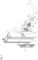
- Figure 1 is an exploded view of a sash according to the invention for a window or for a door with a frame profile 4 with a rotatable handle element 2.
- the sash has a lower rosette 21 with a contact surface 29 on which projections 26 are arranged.
- a bearing flange 22 is rotatably mounted on the lower rosette, to which the handle element 2 is fixed in a rotationally fixed manner, so that the handle element 2 is mounted on the lower rosette 21 so as to be rotatable about an axis H.
- the handle element 2 is fixed here in particular to the bearing flange 22 by means of a fastening means 28 designed as a screw.
- the frame profile 4 in Figure 1 has a recess 1 with a shape deviating from the circular shape.
- the recess 1 is preferably milled or punched into the frame profile 4.
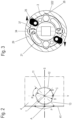
- the recess 1 is in Figure 2 shown enlarged. It has a predominantly circular inner geometry 12, which essentially has a diameter D, in particular from 20 mm to 35 mm, preferably from 25 mm to 30 mm and particularly preferably from 28 mm to 29 mm.
- the recess 1 also has several notches 13, each of which protrudes radially beyond the inner geometry 12 with a maximum depth C of in particular from 0.5 mm to 3 mm, preferably from 1 mm to 2 mm and particularly preferably from 1.1 mm to 1.2 mm.
- the notches 13 each have an outline which corresponds to at least one Section of a circle with a diameter of in particular 4 mm to 12 mm, preferably from 6 mm to 10 mm and particularly preferably from about 8 mm or exactly 8 mm.
- the notches 13 are therefore each designed in the shape of a circular arc.
- the respective circular arc preferably has a radian measure of ⁇ /2 radians to 3 ⁇ /2 radians and particularly preferably from 3 ⁇ /4 radians to ⁇ radians.
- a diameter B of an outermost circumference of the recess 1, which is a circle adjacent to the outermost point of the notches 13, is in particular from 20 mm to 35 mm, preferably from 25 mm to 30 mm and particularly preferably from 28 mm to 29 mm, wherein the diameter B is larger than the diameter D.
- the recess 1 has an axis of symmetry S, so that half of the notches 13 are located on each side of the axis of symmetry S, wherein a length of a circular arc lying on both sides of the recess 1 between the respective halves of the notches 13, through the center of which the axis of symmetry S runs, which extends in particular horizontally, is greater than a length of circular arcs lying between the half of the notches 13 lying on the corresponding side of the axis of symmetry S.
- Circular arcs that start from the respective center of the circles, of which the notches 13 are a part, preferably have a radian measure of ⁇ /5 radians to ⁇ /3 radians and particularly preferably of ⁇ /4 radians.
- a circular arc of the circular inner geometry 12 preferably has a radian measure of ⁇ /4 radians to ⁇ /2 radians and particularly preferably of ⁇ /3 radians.
- the recess 1 in particular also has a vertically extending axis of symmetry V.
- the circular arcs running between all notches 13 are arranged concentrically, so that they form the predominantly circular inner geometry 12 of the recess 1.
- the recess 1 optionally has predominantly the shape of a rosette.
- the recess 1 is as in Figure 1 or 2 with a smallest distance A of in particular 1 mm to 2.5 mm and preferably 1.2 mm to 1.4 mm from a nearest outer edge 41 of the frame profile 4.
- the lower rosette 21 rests against a base 35 of the holding element 3.
- the projections 26 on the contact surface 29 engage in several receptacles 33 in the inner side 31 of the holding element 3.
- the outline of the outer side 32 of the holding element 3 in an area held in the recess 1 essentially corresponds, in particular the projection 321, to an outline of an inner side 11 of the recess 1.
- the holding element 3 is held in the recess 1 in a plane that runs parallel to the plane of the circular inner geometry 12, essentially without play.
- FIG 3 is a cross-section of the lower rosette 21 from Figure 1 shown, which is inserted into the holding element 3, wherein the contact surface 29 has the described projections 26, which engage in the receptacles 33 in the holding element 3.
- the lower rosette 21 is essentially fastened to the holding element 3 by means of two fastening means 25.
- the fastening means 25 have a pivotable area, which can be pivoted into an opening 37 in the shell 322 of the holding element 3 and which secures the lower rosette 21 against axial withdrawal from the holding element 3.
- the outer side 32 of the holding element 3 has according to Figure 1 at least five projections 36 and preferably at least six projections 36 and in particular exactly six projections 36.
- An outline of the projections 36 corresponds to the notches 13.
- the frame profile 4 has a web which has a width T of 1 mm to 5 mm and preferably of 2 mm to 4 mm in the insertion direction of the holding element 3.
- the lower rosette 21 is inserted into the shell-shaped holding element 3.
- the holding element 3 can preferably transmit a torque of in particular 80 Nm to 150 Nm, preferably from 90 Nm to 110 Nm and particularly preferably more than 100 Nm to the frame profile 4, wherein the holding element 3 is held in the recess 1 in a dimensionally stable and form-fitting and/or rotationally fixed manner, so that the requirements of the standard EN 13126-3:2012-02 are met, in particular without the handle element 2 twisting and/or preferably without the frame profile 4 deforming.
- the frame profile 4 and/or the holding element 3 and/or the handle element 2 and/or the lower rosette 21 and/or the bearing flange 22 is preferably made of metal and/or plastic, the metal comprising aluminum in particular.
- a rosette 24 can optionally be attached to the lower rosette.
Landscapes
- Engineering & Computer Science (AREA)
- Mechanical Engineering (AREA)
- Wing Frames And Configurations (AREA)
- Hooks, Suction Cups, And Attachment By Adhesive Means (AREA)
Applications Claiming Priority (1)
| Application Number | Priority Date | Filing Date | Title |
|---|---|---|---|
| DE102023109375.4A DE102023109375A1 (de) | 2023-04-13 | 2023-04-13 | Flügel für ein Fenster oder eine Tür |
Publications (2)
| Publication Number | Publication Date |
|---|---|
| EP4450738A1 true EP4450738A1 (fr) | 2024-10-23 |
| EP4450738B1 EP4450738B1 (fr) | 2025-06-18 |
Family
ID=91248047
Family Applications (1)
| Application Number | Title | Priority Date | Filing Date |
|---|---|---|---|
| EP24165473.0A Active EP4450738B1 (fr) | 2023-04-13 | 2024-03-22 | Battant pour une fenêtre ou une porte |
Country Status (3)
| Country | Link |
|---|---|
| EP (1) | EP4450738B1 (fr) |
| CN (1) | CN118933449A (fr) |
| DE (1) | DE102023109375A1 (fr) |
Citations (7)
| Publication number | Priority date | Publication date | Assignee | Title |
|---|---|---|---|---|
| WO2017103310A1 (fr) * | 2015-12-14 | 2017-06-22 | Sistemas Técnicos Del Accesorio Y Componentes, S.L. | Poignée pour portes et fenêtres et porte ou fenêtre associée |
| WO2018224294A1 (fr) | 2017-06-09 | 2018-12-13 | Franz Schneider Brakel Gmbh + Co Kg | Adaptateur servant au montage d'un élément de retenue d'une poignée de porte ou de fenêtre |
| WO2020074170A1 (fr) * | 2018-10-08 | 2020-04-16 | Hermat-Metallwaren B. Porst GmbH | Système de poignée |
| WO2020126520A1 (fr) * | 2018-12-21 | 2020-06-25 | Franz Schneider Brakel Gmbh + Co Kg | Dispositif de fixation d'une poignée de porte ou de fenêtre |
| EP3680423A2 (fr) | 2019-01-11 | 2020-07-15 | Eugen Notter GmbH Beschlägefabrik | Dispositif rotatif pour poignées de fenêtre et de porte |
| EP3760816A1 (fr) | 2019-07-04 | 2021-01-06 | Franz Schneider Brakel GmbH + Co KG | Dispositif de maintien pour une poignée de porte ou de fenêtre |
| DE102021118158A1 (de) * | 2021-07-14 | 2023-01-19 | Hydro Extruded Solutions As | Schließeinrichtung für eine Drehvorrichtung |
Family Cites Families (1)
| Publication number | Priority date | Publication date | Assignee | Title |
|---|---|---|---|---|
| DE202015101329U1 (de) * | 2015-03-16 | 2016-06-20 | Franz Schneider Brakel Gmbh + Co Kg | Halteelement für einen Tür- oder Fensterdrücker und Anordnung eines Tür- oder Fensterdrückers an einer Aufnahmeöffnung eines Fensterrahmens, eines Türblatts oder dergleichen |
-
2023
- 2023-04-13 DE DE102023109375.4A patent/DE102023109375A1/de active Pending
-
2024
- 2024-03-22 EP EP24165473.0A patent/EP4450738B1/fr active Active
- 2024-04-10 CN CN202410425569.6A patent/CN118933449A/zh active Pending
Patent Citations (7)
| Publication number | Priority date | Publication date | Assignee | Title |
|---|---|---|---|---|
| WO2017103310A1 (fr) * | 2015-12-14 | 2017-06-22 | Sistemas Técnicos Del Accesorio Y Componentes, S.L. | Poignée pour portes et fenêtres et porte ou fenêtre associée |
| WO2018224294A1 (fr) | 2017-06-09 | 2018-12-13 | Franz Schneider Brakel Gmbh + Co Kg | Adaptateur servant au montage d'un élément de retenue d'une poignée de porte ou de fenêtre |
| WO2020074170A1 (fr) * | 2018-10-08 | 2020-04-16 | Hermat-Metallwaren B. Porst GmbH | Système de poignée |
| WO2020126520A1 (fr) * | 2018-12-21 | 2020-06-25 | Franz Schneider Brakel Gmbh + Co Kg | Dispositif de fixation d'une poignée de porte ou de fenêtre |
| EP3680423A2 (fr) | 2019-01-11 | 2020-07-15 | Eugen Notter GmbH Beschlägefabrik | Dispositif rotatif pour poignées de fenêtre et de porte |
| EP3760816A1 (fr) | 2019-07-04 | 2021-01-06 | Franz Schneider Brakel GmbH + Co KG | Dispositif de maintien pour une poignée de porte ou de fenêtre |
| DE102021118158A1 (de) * | 2021-07-14 | 2023-01-19 | Hydro Extruded Solutions As | Schließeinrichtung für eine Drehvorrichtung |
Also Published As
| Publication number | Publication date |
|---|---|
| CN118933449A (zh) | 2024-11-12 |
| DE102023109375A1 (de) | 2024-10-17 |
| EP4450738B1 (fr) | 2025-06-18 |
Similar Documents
| Publication | Publication Date | Title |
|---|---|---|
| EP2163716B1 (fr) | Verrou pour une porte coulissante | |
| DE102005004000A1 (de) | Mitnehmer | |
| EP1916367A2 (fr) | Charnière de porte de véhicule automobile | |
| EP3543434B1 (fr) | Palier de poignée doté d'une poignée de porte ou de fenêtre fixée mobile sur ledit palier de poignée | |
| EP2796645B1 (fr) | Serrure à pêne dormant d'un meuble | |
| DE102011078858A1 (de) | Zur verschieblichen Montage in einer einen Hinterschnitt aufweisenden Beschlagnut vorgesehenes Beschlagteil | |
| WO1993025789A1 (fr) | Fixation reglable de tourillons et de pivots, utile notamment pour portes et portails | |
| EP4450738B1 (fr) | Battant pour une fenêtre ou une porte | |
| DE29713995U1 (de) | Türscharnier mit Feststeller | |
| DE20004943U1 (de) | Verriegelungsvorrichtung mit pilzförmigem Zapfen | |
| EP0318422B1 (fr) | Charnière réglable, en particulier pour portes | |
| EP1780355B1 (fr) | Dispositif d'actionnement d'un capot d'un véhicule automobile | |
| EP1216335A1 (fr) | Engrenage intermediaire destine a des ferrures de portes et fenetres | |
| AT1463U1 (de) | Antriebsanordnung für verdrehbare lamellen eines eine fenster- oder türöffnung abdeckenden ladens | |
| DE102022120478A1 (de) | Betätigungshandhabe | |
| EP3363969A1 (fr) | Poignée d'actionnement | |
| EP1922467B1 (fr) | Charniere pour portes, fenetres ou elements similaires | |
| EP4375456A1 (fr) | Système de fermeture pour portes ou fenêtres | |
| DE102023112864A1 (de) | Beschlag für Türen oder Fenster | |
| DE585035C (de) | Malschloss, dessen aus zwei Teilen bestehendes Gehaeuse nur bei entriegeltem Riegelbolzen geoeffnet werden kann | |
| DE20001006U1 (de) | Blendenkappe für einen Rolladenkasten | |
| DE19736934A1 (de) | Verriegelungsbeschlag | |
| EP1375795B1 (fr) | Ensemble de serrure cylindrique à bouton poussoir | |
| WO2001034926A1 (fr) | Douille de correction angulaire pour l'adaptation de l'angle de montage de poignees quelconques sur des fenetres et des portes | |
| DE20100326U1 (de) | Kantengetriebe für einen Treibstangenbeschlag |
Legal Events
| Date | Code | Title | Description |
|---|---|---|---|
| PUAI | Public reference made under article 153(3) epc to a published international application that has entered the european phase |
Free format text: ORIGINAL CODE: 0009012 |
|
| STAA | Information on the status of an ep patent application or granted ep patent |
Free format text: STATUS: THE APPLICATION HAS BEEN PUBLISHED |
|
| AK | Designated contracting states |
Kind code of ref document: A1 Designated state(s): AL AT BE BG CH CY CZ DE DK EE ES FI FR GB GR HR HU IE IS IT LI LT LU LV MC ME MK MT NL NO PL PT RO RS SE SI SK SM TR |
|
| STAA | Information on the status of an ep patent application or granted ep patent |
Free format text: STATUS: REQUEST FOR EXAMINATION WAS MADE |
|
| 17P | Request for examination filed |
Effective date: 20241115 |
|
| RBV | Designated contracting states (corrected) |
Designated state(s): AL AT BE BG CH CY CZ DE DK EE ES FI FR GB GR HR HU IE IS IT LI LT LU LV MC ME MK MT NL NO PL PT RO RS SE SI SK SM TR |
|
| GRAP | Despatch of communication of intention to grant a patent |
Free format text: ORIGINAL CODE: EPIDOSNIGR1 |
|
| STAA | Information on the status of an ep patent application or granted ep patent |
Free format text: STATUS: GRANT OF PATENT IS INTENDED |
|
| RIC1 | Information provided on ipc code assigned before grant |
Ipc: E05B 3/06 20060101ALI20250120BHEP Ipc: E05B 3/00 20060101AFI20250120BHEP |
|
| INTG | Intention to grant announced |
Effective date: 20250206 |
|
| GRAS | Grant fee paid |
Free format text: ORIGINAL CODE: EPIDOSNIGR3 |
|
| GRAA | (expected) grant |
Free format text: ORIGINAL CODE: 0009210 |
|
| STAA | Information on the status of an ep patent application or granted ep patent |
Free format text: STATUS: THE PATENT HAS BEEN GRANTED |
|
| P01 | Opt-out of the competence of the unified patent court (upc) registered |
Free format text: CASE NUMBER: APP_17837/2025 Effective date: 20250411 |
|
| AK | Designated contracting states |
Kind code of ref document: B1 Designated state(s): AL AT BE BG CH CY CZ DE DK EE ES FI FR GB GR HR HU IE IS IT LI LT LU LV MC ME MK MT NL NO PL PT RO RS SE SI SK SM TR |
|
| REG | Reference to a national code |
Ref country code: GB Ref legal event code: FG4D Free format text: NOT ENGLISH |
|
| REG | Reference to a national code |
Ref country code: CH Ref legal event code: EP |
|
| REG | Reference to a national code |
Ref country code: DE Ref legal event code: R096 Ref document number: 502024000069 Country of ref document: DE |
|
| REG | Reference to a national code |
Ref country code: CH Ref legal event code: EP |
|
| REG | Reference to a national code |
Ref country code: IE Ref legal event code: FG4D Free format text: LANGUAGE OF EP DOCUMENT: GERMAN |
|
| PG25 | Lapsed in a contracting state [announced via postgrant information from national office to epo] |
Ref country code: FI Free format text: LAPSE BECAUSE OF FAILURE TO SUBMIT A TRANSLATION OF THE DESCRIPTION OR TO PAY THE FEE WITHIN THE PRESCRIBED TIME-LIMIT Effective date: 20250618 |
|
| REG | Reference to a national code |
Ref country code: LT Ref legal event code: MG9D |
|
| PG25 | Lapsed in a contracting state [announced via postgrant information from national office to epo] |
Ref country code: GR Free format text: LAPSE BECAUSE OF FAILURE TO SUBMIT A TRANSLATION OF THE DESCRIPTION OR TO PAY THE FEE WITHIN THE PRESCRIBED TIME-LIMIT Effective date: 20250919 Ref country code: NO Free format text: LAPSE BECAUSE OF FAILURE TO SUBMIT A TRANSLATION OF THE DESCRIPTION OR TO PAY THE FEE WITHIN THE PRESCRIBED TIME-LIMIT Effective date: 20250918 |
|
| PG25 | Lapsed in a contracting state [announced via postgrant information from national office to epo] |
Ref country code: BG Free format text: LAPSE BECAUSE OF FAILURE TO SUBMIT A TRANSLATION OF THE DESCRIPTION OR TO PAY THE FEE WITHIN THE PRESCRIBED TIME-LIMIT Effective date: 20250618 |
|
| PG25 | Lapsed in a contracting state [announced via postgrant information from national office to epo] |
Ref country code: HR Free format text: LAPSE BECAUSE OF FAILURE TO SUBMIT A TRANSLATION OF THE DESCRIPTION OR TO PAY THE FEE WITHIN THE PRESCRIBED TIME-LIMIT Effective date: 20250618 |
|
| PG25 | Lapsed in a contracting state [announced via postgrant information from national office to epo] |
Ref country code: RS Free format text: LAPSE BECAUSE OF FAILURE TO SUBMIT A TRANSLATION OF THE DESCRIPTION OR TO PAY THE FEE WITHIN THE PRESCRIBED TIME-LIMIT Effective date: 20250918 |
|
| REG | Reference to a national code |
Ref country code: NL Ref legal event code: MP Effective date: 20250618 |
|
| PG25 | Lapsed in a contracting state [announced via postgrant information from national office to epo] |
Ref country code: LV Free format text: LAPSE BECAUSE OF FAILURE TO SUBMIT A TRANSLATION OF THE DESCRIPTION OR TO PAY THE FEE WITHIN THE PRESCRIBED TIME-LIMIT Effective date: 20250618 |
|
| PG25 | Lapsed in a contracting state [announced via postgrant information from national office to epo] |
Ref country code: NL Free format text: LAPSE BECAUSE OF FAILURE TO SUBMIT A TRANSLATION OF THE DESCRIPTION OR TO PAY THE FEE WITHIN THE PRESCRIBED TIME-LIMIT Effective date: 20250618 |
|
| PG25 | Lapsed in a contracting state [announced via postgrant information from national office to epo] |
Ref country code: PT Free format text: LAPSE BECAUSE OF FAILURE TO SUBMIT A TRANSLATION OF THE DESCRIPTION OR TO PAY THE FEE WITHIN THE PRESCRIBED TIME-LIMIT Effective date: 20251020 |
|
| PG25 | Lapsed in a contracting state [announced via postgrant information from national office to epo] |
Ref country code: IS Free format text: LAPSE BECAUSE OF FAILURE TO SUBMIT A TRANSLATION OF THE DESCRIPTION OR TO PAY THE FEE WITHIN THE PRESCRIBED TIME-LIMIT Effective date: 20251018 |
|
| PG25 | Lapsed in a contracting state [announced via postgrant information from national office to epo] |
Ref country code: SM Free format text: LAPSE BECAUSE OF FAILURE TO SUBMIT A TRANSLATION OF THE DESCRIPTION OR TO PAY THE FEE WITHIN THE PRESCRIBED TIME-LIMIT Effective date: 20250618 |
|
| PG25 | Lapsed in a contracting state [announced via postgrant information from national office to epo] |
Ref country code: CZ Free format text: LAPSE BECAUSE OF FAILURE TO SUBMIT A TRANSLATION OF THE DESCRIPTION OR TO PAY THE FEE WITHIN THE PRESCRIBED TIME-LIMIT Effective date: 20250618 |
|
| PG25 | Lapsed in a contracting state [announced via postgrant information from national office to epo] |
Ref country code: PL Free format text: LAPSE BECAUSE OF FAILURE TO SUBMIT A TRANSLATION OF THE DESCRIPTION OR TO PAY THE FEE WITHIN THE PRESCRIBED TIME-LIMIT Effective date: 20250618 |
|
| PG25 | Lapsed in a contracting state [announced via postgrant information from national office to epo] |
Ref country code: EE Free format text: LAPSE BECAUSE OF FAILURE TO SUBMIT A TRANSLATION OF THE DESCRIPTION OR TO PAY THE FEE WITHIN THE PRESCRIBED TIME-LIMIT Effective date: 20250618 |
|
| PG25 | Lapsed in a contracting state [announced via postgrant information from national office to epo] |
Ref country code: SK Free format text: LAPSE BECAUSE OF FAILURE TO SUBMIT A TRANSLATION OF THE DESCRIPTION OR TO PAY THE FEE WITHIN THE PRESCRIBED TIME-LIMIT Effective date: 20250618 |
|
| PG25 | Lapsed in a contracting state [announced via postgrant information from national office to epo] |
Ref country code: ES Free format text: LAPSE BECAUSE OF FAILURE TO SUBMIT A TRANSLATION OF THE DESCRIPTION OR TO PAY THE FEE WITHIN THE PRESCRIBED TIME-LIMIT Effective date: 20250618 |
|
| PG25 | Lapsed in a contracting state [announced via postgrant information from national office to epo] |
Ref country code: DK Free format text: LAPSE BECAUSE OF FAILURE TO SUBMIT A TRANSLATION OF THE DESCRIPTION OR TO PAY THE FEE WITHIN THE PRESCRIBED TIME-LIMIT Effective date: 20250618 |
|
| PGFP | Annual fee paid to national office [announced via postgrant information from national office to epo] |
Ref country code: DE Payment date: 20260305 Year of fee payment: 3 |
|
| PGFP | Annual fee paid to national office [announced via postgrant information from national office to epo] |
Ref country code: AT Payment date: 20260301 Year of fee payment: 3 |
|
| PGFP | Annual fee paid to national office [announced via postgrant information from national office to epo] |
Ref country code: FR Payment date: 20260305 Year of fee payment: 3 |
|
| PLBE | No opposition filed within time limit |
Free format text: ORIGINAL CODE: 0009261 |
|
| STAA | Information on the status of an ep patent application or granted ep patent |
Free format text: STATUS: NO OPPOSITION FILED WITHIN TIME LIMIT |
|
| REG | Reference to a national code |
Ref country code: CH Ref legal event code: L10 Free format text: ST27 STATUS EVENT CODE: U-0-0-L10-L00 (AS PROVIDED BY THE NATIONAL OFFICE) Effective date: 20260430 |