EP4450746A1 - Système de porte ou de fenêtre coulissante et profilé coulissant destiné à être utilisé dans celui-ci - Google Patents
Système de porte ou de fenêtre coulissante et profilé coulissant destiné à être utilisé dans celui-ci Download PDFInfo
- Publication number
- EP4450746A1 EP4450746A1 EP24170554.0A EP24170554A EP4450746A1 EP 4450746 A1 EP4450746 A1 EP 4450746A1 EP 24170554 A EP24170554 A EP 24170554A EP 4450746 A1 EP4450746 A1 EP 4450746A1
- Authority
- EP
- European Patent Office
- Prior art keywords
- profile
- wall
- free edge
- upper portion
- slidable
- Prior art date
- Legal status (The legal status is an assumption and is not a legal conclusion. Google has not performed a legal analysis and makes no representation as to the accuracy of the status listed.)
- Pending
Links
Images

Classifications
-
- E—FIXED CONSTRUCTIONS
- E06—DOORS, WINDOWS, SHUTTERS, OR ROLLER BLINDS IN GENERAL; LADDERS
- E06B—FIXED OR MOVABLE CLOSURES FOR OPENINGS IN BUILDINGS, VEHICLES, FENCES OR LIKE ENCLOSURES IN GENERAL, e.g. DOORS, WINDOWS, BLINDS, GATES
- E06B3/00—Window sashes, door leaves, or like elements for closing wall or like openings; Layout of fixed or moving closures, e.g. windows in wall or like openings; Features of rigidly-mounted outer frames relating to the mounting of wing frames
- E06B3/32—Arrangements of wings characterised by the manner of movement; Arrangements of movable wings in openings; Features of wings or frames relating solely to the manner of movement of the wing
- E06B3/34—Arrangements of wings characterised by the manner of movement; Arrangements of movable wings in openings; Features of wings or frames relating solely to the manner of movement of the wing with only one kind of movement
- E06B3/42—Sliding wings; Details of frames with respect to guiding
- E06B3/46—Horizontally-sliding wings
- E06B3/4636—Horizontally-sliding wings for doors
Definitions
- the present invention relates to a sliding door or window system with a transparent partition and to a slidable profile for use therein.
- the system can be incorporated into a wall and/or may be used as part of an outdoor framework construction, for example a framework to cover a patio.
- Sliding doors and windows have been used before in both residential and commercial settings. They may have a space-saving design and ability to prolong the usability of a patio roof throughout the year.
- Traditional sliding door and window systems typically consist of a transparent partition, such as a glass pane, mounted on a sliding frame or rail.
- An object of embodiments of the invention is to the increase safety of a sliding door or window system.
- a first aspect of the invention provides a sliding door or window system comprising a transparent partition a slidable profile and a guiding means.
- the transparent partition can be a glass pane.
- the guiding means can be a rail.
- the slidable profile has an upper portion with a free edge and a lower portion with a free edge. The transparent partition is held by the upper portion of the slidable profile and the lower portion of the slidable profile is slidably installed on the guiding means.
- the slidable profile extends from the free edge of the lower portion to the free edge of the upper portion over a distance h which is at least 100 mm, preferably at least 120 mm, more preferably at least 180 mm, even more preferably at least 200 mm, such as 250 mm.
- the safety of the sliding door system is increased. Namely, the awareness of the glass pane or any other transparent partition is promoted since the profile is better visible which thereby takes up attention. As a result, awareness of the transparent partition is increased and possible collision scenarios are thereby reduced.
- the slidable profile has a visible surface area A1 and wherein transparent partition has a visible surface area A2, wherein A1 is at least 18 % of A2, preferably A1 is between 20 % - 120 % of A2, more preferably A1 is between 25 - 90 % of A2.
- A1 is at least 18 % of A2
- A1 is between 20 % - 120 % of A2
- A1 is between 25 - 90 % of A2.
- the system may further have an upper guiding member for guiding an upper portion of the transparent partition during a sliding movement thereof.
- the upper guiding member may be a U shaped rail configured to grab an upper portion of the transparent partition and allow a slidable movement thereof.
- said upper guiding member guiding the upper portion of the transparent partition is understood as a separate member, which is separate from the slidable profile that holds the lower portion transparent partition.
- a further aspect of the invention relates to a slidable profile typically for use in a system as described herein.
- the slidable profile is configured for slidably holding a transparent partition, such as a glass pane, with respect to a guiding means, such as a rail, wherein the slidable profile has an upper portion configured to hold the transparent partition and a lower portion configured to slidably engage with the guiding means.
- the upper portion has a free edge, which can be referred to herein as upper free edge, and the lower portion has a free edge, which can be referred to herein as lower free edge.
- the slidable profile extends from the free edge of the lower portion to the free edge of the upper portion over a distance h which is at least 100 mm, preferably at least 120 mm, more preferably at least 180 mm, even more preferably at least 200 mm, such as 250 mm.
- aspects of the invention are based on the inventive insight that the safety of the sliding door or window system can be increased by having the profile extending from the free edge of the lower portion to the free edge of the upper portion over a relative large distance, i.e. said distance h.
- the profile may define two or more enclosed areas as seen in transversal cross section. In this manner, the profile can be imbued with high strength while maintaining a low overall weight.
- This lightweight design facilitates the smooth and effortless movement of the transparent partition, which is typically a glass pane, such as a glass pane being part of a door or window.
- the two or more enclosed areas are typically arranged between the lower portion and upper portion of the profile such that the profile is provided with a desired strength while maintaining a low overall weight.
- the two or more enclosed areas are adjacently arranged and extend between the free edge of the lower portion and the free edge of the upper portion over a distance d which is at least 35 %, more preferably at least 40 %, even more preferably at least 50 % of distance h. In this manner, a good division of strength is provided to the profile without impairing a low total weight.
- the profile may comprise a first wall extending from the free edge of the lower portion to the free edge of the upper portion.
- the first wall is typically not transparent or less transparent as the transparent partition such that the first wall is easily visible. As a result, a nearby individual will be well aware of the presence of the profile and thus the presence of the glass pane.
- the distance h over which the profile extends from the free edge of the lower portion to the free edge of the upper portion may in some embodiments be at most 1000 mm, preferably at most 950 mm, even more preferably at most 850 mm. In this manner, the glass partition is well protected, and a good awareness is created without impairing visibility. In more preferred embodiments, distance h is at most 600 mm, preferably at most 500 mm, even more preferably at most 450 mm.
- the profile may have a second wall extending substantially parallel to and at a distance of the first wall.
- the first and/or second wall may be painted or provided with a coating to increase durability.
- the second wall is preferably connected to the first wall via one or more webs, preferably at least 2 webs, more preferably at least 3 webs.
- the first wall preferably has side edges, typically two side edges, connecting the free edge of the lower portion to the free edge of the upper portion of the profile.
- the second wall may have side edges, typically two side edges, connecting the free edge of the lower portion to the free edge of the upper portion of the profile.
- the first wall can be a front wall configured to face an outdoor environment.
- the second wall can be a back wall configured to face an indoor environment.
- the term transparent partition can be understood as any transparent member that can function as partitioning a first zone from a second zone. For example partitioning an outside zone from an inside zone or two inside zones.
- the transparent partition typically takes part in functioning as a door or window.
- Transparent is typically understood as near or completely see-through, more in particular meaning that light is allowed to pass through so that objects behind the partition can be distinctly recognized when standing in front of the partition.
- the side edges of the first wall and second wall are substantially parallel to each other.
- the side edges are preferably perpendicular to the lower free edge and upper free edge.
- the first and/or second wall may be substantially rectangular, the side edges of the rectangular shape may extend along a distance which is substantially the same as distance h as described herein, i.e. at least 100 mm, preferably at least 120 mm, more preferably at least 180 mm, even more preferably at least 200 mm, such as 250 mm.
- the distance h may be between 120 - 500 mm.
- At least two webs of the one or more webs extend between and connect opposite side edges of the first wall.
- the webs may continuously extend over the surface of the first wall.
- the same at least two webs of the one or more webs preferably extend between and connect opposite side edges of the second wall.
- the first wall and the second wall have substantially the same length as respectively measured between their side edges. With other words the length as measured between the side edges of the first wall is preferably the same as the length measured between the side edges of the second wall.
- the first wall has a surface area A1 of at least 550 cm 2 , preferably at least 750 cm 2 , more preferably at least 1000 cm 2 , such as 1250 cm 2 .
- the second wall preferably has a similar or the same surface area. In this manner, a good visibility of the profile is ensured which results in an increased safety as chance of accidental collision is reduced. Additionally, it was found that in this manner, the transparent partition could be protected from splashes and/or dirt resulting from rain or pets.
- the upper portion of the profile is a substantially U shaped as seen in transversal cross section. The U shape has legs configured to receive and grab the transparent partition.
- the transparent partition is preferably connected to the profile in a fixed manner, optionally assisted by aid of a glue.
- the upper portion of the profile is provided with one or more grooves, for example three or four grooves, for facilitating holding of the transparent partition.
- the profile typically extends along a vertical axis and the upper portion of the profile is preferably configured to hold the transparent partition such that the transparent partition extends in the same direction as the vertical axis of the profile.
- the lower portion of the profile is substantially U shaped, more preferably this U shape of the lower portion has legs configured to engage with a guiding member of a rail, such as a guiding spine.
- the profile can be manufactured by way of extrusion.
- the profile is an extruded profile and more preferably an extruded aluminum profile.
- the profile may further be subjected to any form of treatment which would increase the properties thereof, for example to make the profile more suitable for an outdoor environment.
- the profile may be provided with a protection coating or paint to increase durability.
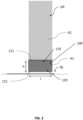
- Figure 1 shows a perspective view of a sliding door system incorporated in a framework construction, for example a patio cover.
- a framework construction for example a patio cover.
- Such construction has the benefit that rain and wind are no longer a game breaker to enjoy a patio and garden views.
- the system S has a glass pane GP as a transparent partition, a slidable profile 100 and a rail RL as a guiding means.
- the transparent partition is held by an upper portion of the slidable profile 100.
- the lower portion of the slidable profile 100 is slidably installed on the rail RL. In this manner, the glass pane GP may be moved in a sliding manner along the rail RL from a first position to a second position, for example from an open position to a closed position, or the other way around.
- Figure 1 shows that the slidable profile 100 has an upper portion with a free edge 111 and a lower portion with a free edge 121.
- the profile 100 extends from the lower free edge 121 of the lower portion to the upper free 111 of the upper portion over a distance h.
- This distance is at least 100 mm, preferably at least 120 mm, such as 250 mm to improve safety and avoid accidental collision.
- the awareness of the glass pane or any other transparent partition is promoted since the profile 100 is better visible which thereby takes up more attention.
- awareness of transparent partition GP is increases and possible collision scenarios are thereby reduced. For example collision by a dog or another type of pet otherwise unaware of the glass partition.
- the slidable profile has a visible surface area A1.
- the glass pane GP has a visible surface area A2.
- the visible surface area A2 is typically understood as the area of the glass pane GP which is not covered, e.g. by the profile 100.
- A1 is at least 18 % of A2, preferably at least 20 %, more preferably at least 30 %.
- the profile 100 and glass pane GP are configured and arranged such that A1 is between 18 % - 120 % of A2, more preferably such that A1 is between 25 - 90 % of A2. This way, safety is further increased and chance of accidental collision is reduced. Additionally, the glass pane is further protected from water splashes and dirt. In particular, the need for cleaning can be reduced as the glass is better protected, e.g. protected against stains or dirt from pets.
- the system may further have an upper guiding member RU for guiding an upper portion of the transparent partition GP during a sliding movement thereof.
- the upper guiding member RU may for example be a U shaped rail as better shown by figure 3 .
- the U shaped rail is preferably configured to grab the upper portion of the partition GP in a manner allowing a sliding movement thereof.
- the upper guiding member RU is separate from the slidable profile 100.
- the transparent partition is frameless or free of a structure arranged surrounding the glass partition. Having a separate upper guiding member allows for easier adjustments and can simplify maintenance.
- Figure 1 shows that the transparent partition GP has an upper edge, a lower edge and side edges. The side edges of the transparent partition GP are free of a frame. By minimizing the frame around the transparent partitions, typically glass panels, a more open feel is offered by allowing a larger see through area.
- a plurality of slidable profiles 100 is used, each individually holding a glass pane GP and each profile is individually installed on a corresponding rail of the guiding means.
- the sliding movement of each glass pane GP may be assisted by a corresponding upper guiding member RU.
- the corresponding upper guiding members as shown are separated from the (lower) slidable profiles 100 by the glass plane.
- the system can also be incorporated into a wall to function as a door or window. Or the system may be used as part of a veranda or any other construction.
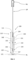
- Figure 2 shows a schematic front view of a slidable profile 100.
- the profile 100 is holding a transparent partition GP.
- the lower portion 120 of the profile is configured to slidably engage with the rail RL such that the profile 100 can slide between a first and a second position thereof.
- the upper portion 110 of the profile 100 is configured to hold the glass pane GP.
- a part of the glass pane GP is held by the profile. Said part is covered and surface area A2 remains visible.
- the distance between the upper free edge 111 and lower free edge 121 is indicated by distance h.
- the upper and lower free edges 111, 121 are connected via parallel side edges.
- the profile 100 as seen from the front view represents a rectangular shape.
- this distance should be at least 100 mm, preferably at least 120 mm, such as 250 mm.
- the profile 100 By configuring the profile 100 to have such a height distance h, typically as measured in an upright position, the profile is more visible, e.g. as seen from an eyesight level.
- the transparent partition e.g. a glass pane GP, being present is increased which reduces risk of accidental collision. It has to be understood that any transparent material can be used to manufacture the partition.
- the profile extends over a distance h which is at least 125 mm, more preferably at least 150 mm such that the glass pane is well protected.
- the distance h over which the profile extends from the free edge of the lower portion to the free edge of the upper portion may be between 130 mm - 450 mm, more preferably between 140 mm - 400 mm, even more preferably between 150 mm - 350 mm, such as 250 mm.
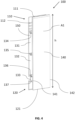
- Figure 3 shows a transversal cross section view of a profile 100 holding a transparent partition GP.
- the profile 100 may have some or all of the features as explained earlier.
- the profile may be the same as the profile illustrated in figures 1 , 2 and 4 .
- Figure 3 shows that the profile has enclosed areas 131,132, 133 as seen in transversal cross section. These areas are arranged between the lower portion 120 and upper portion 110 of the profile 100.
- the enclosed areas 131,132, 133 may have be of similar size or the size thereof may be different.
- Two enclosed areas 131,132 are adjacently arranged and extend between the upper free edge 121 of the lower portion 120 and the lower free edge 111 of the upper portion 110 over a distance d. It is preferred that the distance d is at least 35 %, more preferably at least 40 %, even more preferably at least 50 % of distance h. In this manner, a desired stability and a lightweight total weight can be achieved.
- Figure 3 shows that profile 100 has a first wall 140 extending from the free edge 121 of the lower portion 120 to the free edge 111 of the upper portion 120.
- a second wall 150 extends parallel to and at a distance of the first wall 140.
- the second wall 150 is preferably connected to the first wall 140 via webs 134, 135, 136, 137.
- the upper web 134 in the upper portion of the profile is configured to contact a lower portion of the glass plane GP.
- a middle web 135 is arranged in a middle portion between the upper and lower portion of the profile 100.
- a first web 135 forms a division between enclosed areas 131,132, more in particular first enclosed area 131 and second enclosed area 132, e.g. an upper and lower enclosed area.
- a second web 136 forms a division between enclosed areas 132, 133, for example a or the second enclosed 132 and a third enclosed area 133.
- FIG. 4 shows a perspective cross sectional view of a slidable profile 100.
- the profile 100 extends from a lower edge 121 to an upper edge 111 along distance h.
- the lower portion 120 is configured to slidably engage with guiding means (not shown in figure 4 ).
- the upper portion 110 is configured to receive and hold the transparent partition (not shown in figure 4 ).
- the profile has a first wall 140 and a second wall 150.
- the second wall is substantially parallel to the first wall.
- the walls are connected via webs 134, 135, 136, 137.
- the webs between the first and second wall define enclosed areas 131,132, 133 together with the first wall 140 and second wall 150.
- the enclosed areas 131,132, 133 as shown in figure 4 are arranged between the lower portion 120 and upper portion 110 of the profile 100.
- Figure 4 shows that the first wall 140 has free upper edge 111 in the upper portion 110.
- the second wall 150 has free upper edge (not indicated) in the upper portion 110.
- the first and second wall in the upper portion preferably extends in a tapered manner towards a central longitudinal axis of the profile 100. In this manner, the first wall 140 and second wall 150 have inclined surfaces near the upper free edges.
- the first wall 140 has free lower edge 121 in the lower portion 120.
- the second wall 150 has free lower edge (not indicated) in the lower portion.
- the first wall and second wall in the lower portion 120 preferably extends in a tapered manner away from a central longitudinal axis of the profile 100. In this manner, inclined surfaces are formed on the inside of first wall 140 and second wall 150 which facilitate installation of the profile 100 on a spine or rail of guiding means.
- Figure 4 illustrates that the first wall 140 and second wall 150 have side edges connecting the free edge 121 of the lower portion 120 to the free edge 111 of the upper portion 110 of the profile.
- the side edges of the first wall 140 and second wall 150 are substantially parallel to each other.
- the webs 134, 135, 136, 137 extend between and connect opposite side edges 141, 142 of the first wall 140.
- the webs have a length which equals the distances between side edges 141 and 142.
- the webs extend between and connect opposite side edges of the second wall 150.
- the first wall 140 and the second wall 150 as shown have substantially the same length as measured between their side edges.
- Figure 4 shows first wall 140, e.g. front wall, having a surface area A1. This area typically faces a direction perpendicular to the plane in which the glass plane extends. To increase awareness and avoid accidental collisions, this surface area A1 of the profile is preferably at least 550 cm 2 , preferably at least 750 cm 2 , more preferably at least 1000 cm 2 , such as 1250 cm 2 .
- the second wall 150 e.g. back wall, may have a surface area which is substantially the same as the surface area of front wall 140.
- the upper portion of the profile 100 can have any shape as long as it is capable of holding the glass pane GP.
- Figure 4 illustrates that the upper portion 110 of the profile 100 is a substantially U shaped.
- the U shape in the upper portion 110 of the profile has legs configured to receive and grab a transparent partition.
- the distance between the legs of the U shape typically correspond to the thickness of the glass pane and can be between 8-22 mm, such as 11.2 mm.
- the distance between the legs may be slightly more than thickness of the glass pane.
- the upper portion 110 of the profile 100 may have grooves 112 for facilitating holding of the transparent partition.
- the grooves 112 can be provided on the inside of the legs of the U shaped upper portion 110 of the profile 100 to facilitate holding of the transparent partition.
- profile 100 extends from lower edge to upper edge in a direction similar to the direction along which the transparent partition extends.
- profile 100 extends along a vertical axis (not shown) and upper portion 110 is configured to hold the transparent partition (not shown) such that the transparent partition extends in the same direction as the vertical axis of the profile.
- the lower portion 120 of the profile may be configured in any suitable manner to slidably engage with the guiding means RL.
- Figure 4 illustrates an example wherein the lower portion 120 of the profile 100 is substantially U shaped.
- the legs of the U shape are configured to engage with the guiding means RL, for example a guiding member such as rail or a guiding spine (see for example element RL in figure 3 ).
- the tips of the U shape preferably extend in a tapered manner away from the central longitudinal axis to facility installation of the profile 100 on the guiding means.
Landscapes
- Engineering & Computer Science (AREA)
- Civil Engineering (AREA)
- Structural Engineering (AREA)
- Wing Frames And Configurations (AREA)
Applications Claiming Priority (1)
| Application Number | Priority Date | Filing Date | Title |
|---|---|---|---|
| NL2034597A NL2034597B1 (en) | 2023-04-17 | 2023-04-17 | Sliding door or window system and slidable profile for use therein |
Publications (1)
| Publication Number | Publication Date |
|---|---|
| EP4450746A1 true EP4450746A1 (fr) | 2024-10-23 |
Family
ID=86732405
Family Applications (1)
| Application Number | Title | Priority Date | Filing Date |
|---|---|---|---|
| EP24170554.0A Pending EP4450746A1 (fr) | 2023-04-17 | 2024-04-16 | Système de porte ou de fenêtre coulissante et profilé coulissant destiné à être utilisé dans celui-ci |
Country Status (2)
| Country | Link |
|---|---|
| EP (1) | EP4450746A1 (fr) |
| NL (1) | NL2034597B1 (fr) |
Citations (2)
| Publication number | Priority date | Publication date | Assignee | Title |
|---|---|---|---|---|
| US20150259971A1 (en) * | 2014-03-14 | 2015-09-17 | Mitsubishi Heavy Industries Transportation Equipment Engineering & Service Co., Ltd. | Door of platform door apparatus |
| US20190145155A1 (en) * | 2016-05-03 | 2019-05-16 | Technoform Bautec Holding Gmbh | Sash for a sliding window or a sliding door and method for providing an untreated metal surface in such a sash |
-
2023
- 2023-04-17 NL NL2034597A patent/NL2034597B1/en active
-
2024
- 2024-04-16 EP EP24170554.0A patent/EP4450746A1/fr active Pending
Patent Citations (2)
| Publication number | Priority date | Publication date | Assignee | Title |
|---|---|---|---|---|
| US20150259971A1 (en) * | 2014-03-14 | 2015-09-17 | Mitsubishi Heavy Industries Transportation Equipment Engineering & Service Co., Ltd. | Door of platform door apparatus |
| US20190145155A1 (en) * | 2016-05-03 | 2019-05-16 | Technoform Bautec Holding Gmbh | Sash for a sliding window or a sliding door and method for providing an untreated metal surface in such a sash |
Also Published As
| Publication number | Publication date |
|---|---|
| NL2034597B1 (en) | 2024-10-24 |
Similar Documents
| Publication | Publication Date | Title |
|---|---|---|
| US3693293A (en) | Protective sliding wall panel assembly | |
| US4335547A (en) | Balcony greenhouse | |
| EP0577669B1 (fr) | Systeme a element coulissant | |
| US5848505A (en) | Outdoor window shutter | |
| US7617650B1 (en) | Fascia-mounted aluminum railing system | |
| US9328549B1 (en) | Frame with thermal barrier | |
| US20050092447A1 (en) | Sectional overhead garage door having the simulated appearance of a carriage house door | |
| WO2011088113A1 (fr) | Enceinte mobile | |
| US20230243212A1 (en) | Window shade mounting system for curtain walls | |
| US9447579B2 (en) | Sliding door and pivoting door for demountable wall system | |
| EP4450746A1 (fr) | Système de porte ou de fenêtre coulissante et profilé coulissant destiné à être utilisé dans celui-ci | |
| CA2938335A1 (fr) | Systeme de division | |
| ES2558743T5 (es) | Sistema de puerta | |
| KR20160062513A (ko) | 투명 난간 중간 매입형 이중창호구조 | |
| CN216196135U (zh) | 一种结合门窗幕墙一体化设计的雨棚构造 | |
| EP3124716B1 (fr) | Système de protection solaire avec une pergola mobile | |
| JP6978194B2 (ja) | 大扉装置 | |
| EP3020906B1 (fr) | Dispositif d'entraînement de porte coulissante et kit pour équiper une façade avec un tel dispositif | |
| WO1994019572A1 (fr) | Element de construction de façades | |
| RU157131U1 (ru) | Жалюзийная панель | |
| JP2008303570A (ja) | バルコニ付き建物 | |
| AU2023436475B2 (en) | Single-unit double-track blind system with fly net and blind | |
| CN221032250U (zh) | 一种用于玻璃幕墙消防救援窗位置的可开启式玻璃栏板 | |
| AU2013248234B2 (en) | An airstream diverter for a glazing assembly | |
| KR101468461B1 (ko) | 갤러리용 전동식 창호 |
Legal Events
| Date | Code | Title | Description |
|---|---|---|---|
| PUAI | Public reference made under article 153(3) epc to a published international application that has entered the european phase |
Free format text: ORIGINAL CODE: 0009012 |
|
| STAA | Information on the status of an ep patent application or granted ep patent |
Free format text: STATUS: THE APPLICATION HAS BEEN PUBLISHED |
|
| AK | Designated contracting states |
Kind code of ref document: A1 Designated state(s): AL AT BE BG CH CY CZ DE DK EE ES FI FR GB GR HR HU IE IS IT LI LT LU LV MC ME MK MT NL NO PL PT RO RS SE SI SK SM TR |
|
| STAA | Information on the status of an ep patent application or granted ep patent |
Free format text: STATUS: REQUEST FOR EXAMINATION WAS MADE |
|
| 17P | Request for examination filed |
Effective date: 20250416 |