EP4450812A1 - Verfahren zum betreiben eines luftverdichters - Google Patents
Verfahren zum betreiben eines luftverdichters Download PDFInfo
- Publication number
- EP4450812A1 EP4450812A1 EP23168681.7A EP23168681A EP4450812A1 EP 4450812 A1 EP4450812 A1 EP 4450812A1 EP 23168681 A EP23168681 A EP 23168681A EP 4450812 A1 EP4450812 A1 EP 4450812A1
- Authority
- EP
- European Patent Office
- Prior art keywords
- compressor
- coolant
- cooling system
- cooling
- air
- Prior art date
- Legal status (The legal status is an assumption and is not a legal conclusion. Google has not performed a legal analysis and makes no representation as to the accuracy of the status listed.)
- Withdrawn
Links
Images
Classifications
-
- F—MECHANICAL ENGINEERING; LIGHTING; HEATING; WEAPONS; BLASTING
- F04—POSITIVE - DISPLACEMENT MACHINES FOR LIQUIDS; PUMPS FOR LIQUIDS OR ELASTIC FLUIDS
- F04B—POSITIVE-DISPLACEMENT MACHINES FOR LIQUIDS; PUMPS
- F04B39/00—Component parts, details, or accessories, of pumps or pumping systems specially adapted for elastic fluids, not otherwise provided for in, or of interest apart from, groups F04B25/00 - F04B37/00
- F04B39/06—Cooling; Heating; Prevention of freezing
- F04B39/064—Cooling by a cooling jacket in the pump casing
Definitions
- the present invention relates to a method for operating an air compressor in an air pressure supply system of a vehicle electrically driven by traction batteries, the compressor having a cooling system in which a coolant is conducted by coolant lines and/or by ducts or cavities belonging to a compressor housing into that compressor sections, which are subject to increased temperature load due to the operation of the compressor, said coolant being discharged via further coolant lines after absorption of at least part of the heat generated there and discharging the absorbed heat into regions outside the compressor.
- a specified operating time also known as duty cycle, is specified when a device, without overheating, can only provide the rated power temporarily. This is usually the case if the dissipated heat cannot be dissipated quickly enough, and damage or premature failure would therefore be expected in the long term.
- Duty cycle is defined as the maximum permissible operating interval of a piece of equipment, after which a rest phase must take place in order not to damage or destroy the equipment.
- a given duty cycle may result in limited availability of such a working machine, e.g., a compressor, which is undesirable.
- DE 40 26 684 discloses a device for saving energy in a piston compressor for generating compressed air in motor vehicles.
- the cylinder head can be equipped with cooling channels in which water, or another cooling liquid flows to cool the piston compressor.
- Cooling systems in vehicles or for individual devices present in vehicles are also known.
- DE 10 2018 121 227 A1 discloses a modular commercial vehicle which has, among other things, a cooling system for active cooling of high-voltage energy storage devices. Without detailed presentation, it is also disclosed there that the cooling system should be able to cool further electrical components and for this purpose is to have a cooling interface via which the further components can be connected.
- EP 2 151 344 A1 discloses a hybrid vehicle with a hybrid vehicle drive system comprising an electric motor that can be operated as a generator and a gas engine being operated as an internal combustion engine.
- the electric motor is also intended to be able to drive auxiliary units and is liquid-cooled, whereby the cooling circuits of the electric motor and the cooling circuit of the gas engine can be connected.
- the object to design such an air compressor cooling system is solved by the features of claim 6, while further embodiments are disclosed in the claims dependent on claim 6.
- the first object of the invention is achieved through a method to operate said air compressor in such a way that the cooling system of the compressor is connected to at least one cooling system of the electrically driven vehicle and the coolant present therein is used for cooling the compressor.
- cooling of the compressor is carried out by means of cooling liquids circulating in cooling systems already present and provided with all the necessary devices for heat dissipation. Either no duty cycle needs to be specified at all or a duty circle may be specified, which is much longer and provides sufficient and extended availability of the compressor.
- cooling system of the compressor is connected to a cooling system of the traction batteries and wherein the latter's coolant is used in the cooling system of the compressor.
- the cooling system of the traction batteries is usually designed in such a way that the temperature of the batteries does not exceed a maximum temperature of 40° C, for example, this cooling system is also ideally suited for cooling the compressor of a compressed air system in the vehicle.
- the coolant is provided for cooling a reciprocating piston compressor, and the coolant is guided close to the cylinder head of the reciprocating compressor. This achieves targeted cooling of the areas of a reciprocating compressor most exposed to thermal stress. The operating time of the compressor is thus significantly extended.
- the coolant is used to cool a compressor for supplying compressed air to a vehicle air suspension system.
- the coolant is used to cool a compressor for supplying compressed air to a cleaning system for vehicle, in particular a compressed air cleaning system for sensors, it is important to reduce thermal stress of the compressor and to extend availability.
- the above-mentioned further object of the invention is achieved through an air compressor cooling system of an air pressure supply system of a vehicle electrically driven by traction or drive batteries, in which a coolant is conducted in first coolant lines and/or in ducts or cavities belonging to a compressor housing into that compressor sections, which are subject to increased temperature load due to the operation of the compressor, said coolant being dischargeable via second coolant lines after at least some of the compressor's heat has been absorbed, said heat thereby being dissipated into regions outside the compressor, whereby the cooling system of the compressor is connected via said first and second coolant lines to a cooling system of the traction or drive batteries, and coolant lines, ducts or cavities are provided in which the coolant of the cooling system of the traction or drive batteries is conducted to those sections of the compressor which are subject to increased temperature stress due to the operation of the compressor.
- the air compressor is a reciprocating piston compressor
- said coolant lines and/or ducts or cavities running close to the cylinder head of the piston compressor, thereby being arranged in such a way that the heat of the cylinder head can be dissipated by the coolant.
- a cylinder head with cooling lines/cooling ducts suitable for this purpose can be designed and manufactured without difficulty and is well suited for air compressors designed to supply compressed air to a vehicle air suspension system.
- coolant lines of the compressor cooling system form a cooling circuit with an inlet and a return, the inlet and return each being connected to the cooling system of the traction or drive batteries via branches, preferably 3-way valves, the inlet having at least one solenoid valve, which can be actuated via a control device, for opening and closing the inlet, preferably a switchable 2/2-way valve.
- the air compressor is provided with at least one temperature sensor in areas of increased temperature load and the solenoid valve can be switched by the control device as a function of the signals from the temperature sensors. This provides an easy way to adjust the cooling capacity to the current demand.
- the cooling circuit of the compressor cooling system is arranged in parallel to a cooling circuit of the traction or drive battery cooling system and the inlet of the compressor cooling system's cooling circuit is located at a line section of the drive battery cooling system's cooling circuit before the coolant of the latter enters other elements or devices in which heat is dissipated or released by the coolant.
- Other elements or devices in this context primarily include the vehicle's battery system to be cooled, i.e. where the heat from the batteries is dissipated by the coolant, but also devices for heat release, such as auxiliary or parking heaters, or cabin heaters.
- a further development of the invention is foreseen, wherein a cooler is provided in which the absorbed heat is extracted from the coolant after passing through one or more of the cooling systems.
- the invention also relates to a reciprocating piston compressor to supply compressed air in a vehicle air suspension, where the compressor is equipped with the cooling system according to the invention and to a vehicle air suspension system provided with such a compressor.
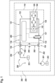
- FIG. 1 shows, only as a rough sketch, partly as a black box sketch and using technical symbols, an air compressor 100 which has an air compressor cooling system 110 and which is a part of an air pressure supply system 120 for an air suspension system in a vehicle 300, neither of which is shown in more detail here.
- the vehicle 300 is electrically driven by traction or drive batteries, the batteries also are not depicted here in details.
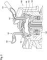
- the air compressor 100 is designed here as a reciprocating piston compressor, the upper part of which is shown in Fig. 2 .
- the air compressor 100 is driven by an electric motor 101.
- a coolant is conducted in first coolant lines 130 and in ducts 141 or cavities 142 belonging to a compressor housing 140, as can be seen better in Fig. 2 .
- Said first coolant lines 130, ducts 141 and cavities 142 conduct the coolant into that compressor sections, which are subject to increased temperature load due to the operation of the air compressor 100.
- the coolant is discharged from said compressor sections via said ducts 141 and/or second coolant lines 131 after at least some of the compressor's heat has been absorbed by the coolant.
- the absorbed heat is then discharged / dissipated within devices outside the air compressor 100, e.g., in the cooler 204.
- Fig. 2 clearly shows, that in the cooling system 110 of the reciprocating piston compressor 100, said ducts 141 or cavities 142 are running close to or inside a cylinder head 143 of the piston compressor 100, thereby being arranged in such a way that the heat of the cylinder head 143 can be dissipated by the coolant.
- the cylinder head 143 is that section of the compressor 100 which is subject to increased temperature stress due to high compression of air through the reciprocating piston 144.
- Figs. 1 and 2 shows that the compressor cooling system 110 is connected to another cooling system 200 in the vehicle 300, in this case and in accordance with the invention to the cooling system 200 of the traction or drive batteries.
- said first and second coolant lines 130, 131, ducts 141 or cavities 142 are provided to conduct the coolant of the cooling system 200 of the traction or drive batteries to those sections of the compressor 100 which are subject to increased temperature stress i.e. to the cylinder head 143.
- Coolant lines 130 and 131 form a cooling circuit 132 with an inlet 133 and a return 134, the inlet 133 and return 134 each being connected to the cooling system 200 of the traction or drive batteries via branches 135, 136, designed as 3-way valves 135, 136, the inlet 133 having a solenoid valve 137 which can be actuated via a control device 400, for opening and closing the inlet 133.
- the solenoid valve 137 is a switchable 2/2-way valve.
- the solenoid valve me be integrated in the compressor housing but can just as well be designed as a separate solenoid valve 137 in the compressor cooling system 110, as it is here.
- the solenoid valve 137 is switched by the control device 400 or by signal from control device as a function of a predefined running time of compressor 100.
- Fig. 1 also shows the basic equipment of the cooling system 200 for the traction or drive batteries.
- a pump 201 which delivers the coolant/cooling liquid, in this case water, via various cooling lines 202 into elements or devices 205 of the traction drive battery cooling system 200
- the cooling system 200 has a reservoir 203, a cooler 204 for heat dissipation and is connected to the branches 135, 136 of the compressor cooling system 110.
- Various system elements or devices 205 in which heat is dissipated or released by the coolant of cooling system 200, also form a part of the traction drive battery cooling system 200. Such elements or devices 205 are shown here merely symbolically.
- These various elements or devices 205 primarily include the vehicle's battery system to be cooled, i.e., where the batteries heat is dissipated by the coolant, but may also include devices for heat release, such as auxiliary heaters or cabin heaters.
- Fig. 1 and 2 it is clear that when the solenoid valve 137 is closed, the coolant cannot circulate through the compressor cooling system 110, but only through the remaining part of the cooling system of the traction batteries 200. If the solenoid valve 137 is opened by a signal of the controller device 400 the coolant enters the compressor cooling system 110 via inlet 133 and through coolant lines 130 and is guided through the ducts 141 and cavities 142 to the compressor housing 140 and the cylinder head 143. The Coolant flowing through the compressor housing 140 and through the cylinder head 143 reduces the temperature of the compressor 100 which leads to improved operation time.
- the cooling circuit 132 belonging to the compressor cooling system 110 thereby is arranged in parallel to a cooling circuit 206 belonging to the traction or drive battery cooling system 200.
- the inlet 133 of the cooling circuit 132 is located at a line section of the cooling circuit 206 before the coolant of the latter enters said other devices 205 in which heat is dissipated or released by the coolant.
- the coolant After passing the compressor cooling system 110 the coolant is directed via cooling lines 131 to return 134, where it is fed via the 3-way valve 136 into the so-called "hot side" of the drive battery cooling system 200.
- the heat absorbed by the coolant from both the compressor cooling system 110 and the from the drive battery cooling system 200 is then dissipated via the cooler 204.
Landscapes
- Engineering & Computer Science (AREA)
- Mechanical Engineering (AREA)
- General Engineering & Computer Science (AREA)
- Compressors, Vaccum Pumps And Other Relevant Systems (AREA)
Priority Applications (1)
| Application Number | Priority Date | Filing Date | Title |
|---|---|---|---|
| EP23168681.7A EP4450812A1 (de) | 2023-04-19 | 2023-04-19 | Verfahren zum betreiben eines luftverdichters |
Applications Claiming Priority (1)
| Application Number | Priority Date | Filing Date | Title |
|---|---|---|---|
| EP23168681.7A EP4450812A1 (de) | 2023-04-19 | 2023-04-19 | Verfahren zum betreiben eines luftverdichters |
Publications (1)
| Publication Number | Publication Date |
|---|---|
| EP4450812A1 true EP4450812A1 (de) | 2024-10-23 |
Family
ID=86095958
Family Applications (1)
| Application Number | Title | Priority Date | Filing Date |
|---|---|---|---|
| EP23168681.7A Withdrawn EP4450812A1 (de) | 2023-04-19 | 2023-04-19 | Verfahren zum betreiben eines luftverdichters |
Country Status (1)
| Country | Link |
|---|---|
| EP (1) | EP4450812A1 (de) |
Citations (6)
| Publication number | Priority date | Publication date | Assignee | Title |
|---|---|---|---|---|
| DE4026684A1 (de) | 1990-08-23 | 1992-02-27 | Knorr Bremse Ag | Einrichtung zur leistungseinsparung bei kolbenverdichtern, insbesondere fuer die drucklufterzeugung in kraftfahrzeugen |
| US20090254246A1 (en) * | 2008-04-02 | 2009-10-08 | International Truck Intellectual Property Company, Llc | Method and apparatus to optimize energy efficiency of air compressor in vehicle air brake application |
| EP2151344A1 (de) | 2008-08-05 | 2010-02-10 | Desider Boda | Vorrichtung, Anordnung und Verfahren eines Fahrzeuges und Fahrzeugantriebs |
| US20170008407A1 (en) * | 2015-07-10 | 2017-01-12 | Ford Global Technologies, Llc | Preconditioning an Electric Vehicle |
| DE102018121227A1 (de) | 2018-08-30 | 2020-03-05 | Man Truck & Bus Se | Modular aufgebautes Nutzfahrzeug |
| US20200240403A1 (en) * | 2017-07-21 | 2020-07-30 | Voith Patent Gmbh | Reciprocating piston machine with cooling device |
-
2023
- 2023-04-19 EP EP23168681.7A patent/EP4450812A1/de not_active Withdrawn
Patent Citations (6)
| Publication number | Priority date | Publication date | Assignee | Title |
|---|---|---|---|---|
| DE4026684A1 (de) | 1990-08-23 | 1992-02-27 | Knorr Bremse Ag | Einrichtung zur leistungseinsparung bei kolbenverdichtern, insbesondere fuer die drucklufterzeugung in kraftfahrzeugen |
| US20090254246A1 (en) * | 2008-04-02 | 2009-10-08 | International Truck Intellectual Property Company, Llc | Method and apparatus to optimize energy efficiency of air compressor in vehicle air brake application |
| EP2151344A1 (de) | 2008-08-05 | 2010-02-10 | Desider Boda | Vorrichtung, Anordnung und Verfahren eines Fahrzeuges und Fahrzeugantriebs |
| US20170008407A1 (en) * | 2015-07-10 | 2017-01-12 | Ford Global Technologies, Llc | Preconditioning an Electric Vehicle |
| US20200240403A1 (en) * | 2017-07-21 | 2020-07-30 | Voith Patent Gmbh | Reciprocating piston machine with cooling device |
| DE102018121227A1 (de) | 2018-08-30 | 2020-03-05 | Man Truck & Bus Se | Modular aufgebautes Nutzfahrzeug |
Similar Documents
| Publication | Publication Date | Title |
|---|---|---|
| US8148859B2 (en) | Cooling structure for inverter and capacitor accommodated integrally with motor in housing of motor, motor unit with cooling structure, and housing | |
| US6678972B2 (en) | Hybrid construction equipment | |
| JP5336467B2 (ja) | 車両用バッテリ冷却装置 | |
| EP3666570B1 (de) | Batteriewärmeverwaltungssystem für ein fahrzeug | |
| CA2593727C (en) | Drive for a vehicle, especially a tracked vehicle or a vehicle with wheel-based steering | |
| KR20210138200A (ko) | 친환경 차량의 회생제동 제어 시스템 | |
| US9546589B2 (en) | Integrated cooling system and method for engine-powered unit | |
| CN110552753B (zh) | 电动油泵系统 | |
| KR101021997B1 (ko) | 하이브리드 자동차 | |
| GB2370107A (en) | A method and system for cooling a hybrid electric vehicle. | |
| EP4253129A1 (de) | Kühlsystem für ein elektrofahrzeug | |
| EP4489985A1 (de) | Elektrisches fahrzeugantriebsmodul mit wärmeverwaltungssystem | |
| JP2014073802A (ja) | 電気自動車用の冷却システム | |
| US12296667B2 (en) | Soil processing machine | |
| US9722473B2 (en) | Construction machine with oil-cooled generator | |
| CN102700400A (zh) | 一种新能源汽车散热系统及热管理控制方法 | |
| US7810457B2 (en) | System and method for controlling oil temperature of an internal combustion engine in a motor vehicle | |
| EP4450812A1 (de) | Verfahren zum betreiben eines luftverdichters | |
| KR20200104645A (ko) | 전기자동차의 냉각 시스템 | |
| JP3728747B2 (ja) | ハイブリッド車の冷却装置 | |
| US10225961B2 (en) | System and method for cooling power electronics | |
| EP4113704B1 (de) | Kühlsystem und verfahren zur steuerung eines kühlsystems | |
| KR102394804B1 (ko) | 자동변속기용 전동식 오일펌프의 모터 냉각 장치 | |
| US6857510B2 (en) | Forced air cooling system for vehicle driveline components | |
| US20240227540A9 (en) | Coolant circuit for a self-propelled working machine comprising multiple electric drive components |
Legal Events
| Date | Code | Title | Description |
|---|---|---|---|
| PUAI | Public reference made under article 153(3) epc to a published international application that has entered the european phase |
Free format text: ORIGINAL CODE: 0009012 |
|
| STAA | Information on the status of an ep patent application or granted ep patent |
Free format text: STATUS: THE APPLICATION HAS BEEN PUBLISHED |
|
| AK | Designated contracting states |
Kind code of ref document: A1 Designated state(s): AL AT BE BG CH CY CZ DE DK EE ES FI FR GB GR HR HU IE IS IT LI LT LU LV MC ME MK MT NL NO PL PT RO RS SE SI SK SM TR |
|
| STAA | Information on the status of an ep patent application or granted ep patent |
Free format text: STATUS: THE APPLICATION IS DEEMED TO BE WITHDRAWN |
|
| 18D | Application deemed to be withdrawn |
Effective date: 20250424 |