EP4450843A1 - Bremsvorrichtung - Google Patents
Bremsvorrichtung Download PDFInfo
- Publication number
- EP4450843A1 EP4450843A1 EP23183660.2A EP23183660A EP4450843A1 EP 4450843 A1 EP4450843 A1 EP 4450843A1 EP 23183660 A EP23183660 A EP 23183660A EP 4450843 A1 EP4450843 A1 EP 4450843A1
- Authority
- EP
- European Patent Office
- Prior art keywords
- pad
- brake
- movable nut
- bolt
- thruster
- Prior art date
- Legal status (The legal status is an assumption and is not a legal conclusion. Google has not performed a legal analysis and makes no representation as to the accuracy of the status listed.)
- Granted
Links
Images



Classifications
-
- F—MECHANICAL ENGINEERING; LIGHTING; HEATING; WEAPONS; BLASTING
- F16—ENGINEERING ELEMENTS AND UNITS; GENERAL MEASURES FOR PRODUCING AND MAINTAINING EFFECTIVE FUNCTIONING OF MACHINES OR INSTALLATIONS; THERMAL INSULATION IN GENERAL
- F16D—COUPLINGS FOR TRANSMITTING ROTATION; CLUTCHES; BRAKES
- F16D55/00—Brakes with substantially-radial braking surfaces pressed together in axial direction, e.g. disc brakes
- F16D55/02—Brakes with substantially-radial braking surfaces pressed together in axial direction, e.g. disc brakes with axially-movable discs or pads pressed against axially-located rotating members
- F16D55/22—Brakes with substantially-radial braking surfaces pressed together in axial direction, e.g. disc brakes with axially-movable discs or pads pressed against axially-located rotating members by clamping an axially-located rotating disc between movable braking members, e.g. movable brake discs or brake pads
- F16D55/224—Brakes with substantially-radial braking surfaces pressed together in axial direction, e.g. disc brakes with axially-movable discs or pads pressed against axially-located rotating members by clamping an axially-located rotating disc between movable braking members, e.g. movable brake discs or brake pads with a common actuating member for the braking members
- F16D55/225—Brakes with substantially-radial braking surfaces pressed together in axial direction, e.g. disc brakes with axially-movable discs or pads pressed against axially-located rotating members by clamping an axially-located rotating disc between movable braking members, e.g. movable brake discs or brake pads with a common actuating member for the braking members the braking members being brake pads
- F16D55/226—Brakes with substantially-radial braking surfaces pressed together in axial direction, e.g. disc brakes with axially-movable discs or pads pressed against axially-located rotating members by clamping an axially-located rotating disc between movable braking members, e.g. movable brake discs or brake pads with a common actuating member for the braking members the braking members being brake pads in which the common actuating member is moved axially, e.g. floating caliper disc brakes
-
- F—MECHANICAL ENGINEERING; LIGHTING; HEATING; WEAPONS; BLASTING
- F16—ENGINEERING ELEMENTS AND UNITS; GENERAL MEASURES FOR PRODUCING AND MAINTAINING EFFECTIVE FUNCTIONING OF MACHINES OR INSTALLATIONS; THERMAL INSULATION IN GENERAL
- F16D—COUPLINGS FOR TRANSMITTING ROTATION; CLUTCHES; BRAKES
- F16D65/00—Parts or details
- F16D65/14—Actuating mechanisms for brakes; Means for initiating operation at a predetermined position
- F16D65/16—Actuating mechanisms for brakes; Means for initiating operation at a predetermined position arranged in or on the brake
- F16D65/18—Actuating mechanisms for brakes; Means for initiating operation at a predetermined position arranged in or on the brake adapted for drawing members together, e.g. for disc brakes
-
- B—PERFORMING OPERATIONS; TRANSPORTING
- B60—VEHICLES IN GENERAL
- B60T—VEHICLE BRAKE CONTROL SYSTEMS OR PARTS THEREOF; BRAKE CONTROL SYSTEMS OR PARTS THEREOF, IN GENERAL; ARRANGEMENT OF BRAKING ELEMENTS ON VEHICLES IN GENERAL; PORTABLE DEVICES FOR PREVENTING UNWANTED MOVEMENT OF VEHICLES; VEHICLE MODIFICATIONS TO FACILITATE COOLING OF BRAKES
- B60T11/00—Transmitting braking action from initiating means to ultimate brake actuator without power assistance or drive or where such assistance or drive is irrelevant
- B60T11/10—Transmitting braking action from initiating means to ultimate brake actuator without power assistance or drive or where such assistance or drive is irrelevant transmitting by fluid means, e.g. hydraulic
- B60T11/101—Transmitting braking action from initiating means to ultimate brake actuator without power assistance or drive or where such assistance or drive is irrelevant transmitting by fluid means, e.g. hydraulic equalising arrangements
-
- F—MECHANICAL ENGINEERING; LIGHTING; HEATING; WEAPONS; BLASTING
- F16—ENGINEERING ELEMENTS AND UNITS; GENERAL MEASURES FOR PRODUCING AND MAINTAINING EFFECTIVE FUNCTIONING OF MACHINES OR INSTALLATIONS; THERMAL INSULATION IN GENERAL
- F16D—COUPLINGS FOR TRANSMITTING ROTATION; CLUTCHES; BRAKES
- F16D65/00—Parts or details
- F16D65/005—Components of axially engaging brakes not otherwise provided for
- F16D65/0068—Brake calipers
-
- F—MECHANICAL ENGINEERING; LIGHTING; HEATING; WEAPONS; BLASTING
- F16—ENGINEERING ELEMENTS AND UNITS; GENERAL MEASURES FOR PRODUCING AND MAINTAINING EFFECTIVE FUNCTIONING OF MACHINES OR INSTALLATIONS; THERMAL INSULATION IN GENERAL
- F16D—COUPLINGS FOR TRANSMITTING ROTATION; CLUTCHES; BRAKES
- F16D65/00—Parts or details
- F16D65/14—Actuating mechanisms for brakes; Means for initiating operation at a predetermined position
- F16D65/16—Actuating mechanisms for brakes; Means for initiating operation at a predetermined position arranged in or on the brake
- F16D65/18—Actuating mechanisms for brakes; Means for initiating operation at a predetermined position arranged in or on the brake adapted for drawing members together, e.g. for disc brakes
- F16D65/183—Actuating mechanisms for brakes; Means for initiating operation at a predetermined position arranged in or on the brake adapted for drawing members together, e.g. for disc brakes with force-transmitting members arranged side by side acting on a spot type force-applying member
-
- F—MECHANICAL ENGINEERING; LIGHTING; HEATING; WEAPONS; BLASTING
- F16—ENGINEERING ELEMENTS AND UNITS; GENERAL MEASURES FOR PRODUCING AND MAINTAINING EFFECTIVE FUNCTIONING OF MACHINES OR INSTALLATIONS; THERMAL INSULATION IN GENERAL
- F16D—COUPLINGS FOR TRANSMITTING ROTATION; CLUTCHES; BRAKES
- F16D65/00—Parts or details
- F16D65/78—Features relating to cooling
- F16D65/84—Features relating to cooling for disc brakes
- F16D65/847—Features relating to cooling for disc brakes with open cooling system, e.g. cooled by air
-
- F—MECHANICAL ENGINEERING; LIGHTING; HEATING; WEAPONS; BLASTING
- F16—ENGINEERING ELEMENTS AND UNITS; GENERAL MEASURES FOR PRODUCING AND MAINTAINING EFFECTIVE FUNCTIONING OF MACHINES OR INSTALLATIONS; THERMAL INSULATION IN GENERAL
- F16D—COUPLINGS FOR TRANSMITTING ROTATION; CLUTCHES; BRAKES
- F16D55/00—Brakes with substantially-radial braking surfaces pressed together in axial direction, e.g. disc brakes
- F16D2055/0075—Constructional features of axially engaged brakes
- F16D2055/0091—Plural actuators arranged side by side on the same side of the rotor
-
- F—MECHANICAL ENGINEERING; LIGHTING; HEATING; WEAPONS; BLASTING
- F16—ENGINEERING ELEMENTS AND UNITS; GENERAL MEASURES FOR PRODUCING AND MAINTAINING EFFECTIVE FUNCTIONING OF MACHINES OR INSTALLATIONS; THERMAL INSULATION IN GENERAL
- F16D—COUPLINGS FOR TRANSMITTING ROTATION; CLUTCHES; BRAKES
- F16D2121/00—Type of actuator operation force
- F16D2121/18—Electric or magnetic
- F16D2121/24—Electric or magnetic using motors
-
- F—MECHANICAL ENGINEERING; LIGHTING; HEATING; WEAPONS; BLASTING
- F16—ENGINEERING ELEMENTS AND UNITS; GENERAL MEASURES FOR PRODUCING AND MAINTAINING EFFECTIVE FUNCTIONING OF MACHINES OR INSTALLATIONS; THERMAL INSULATION IN GENERAL
- F16D—COUPLINGS FOR TRANSMITTING ROTATION; CLUTCHES; BRAKES
- F16D2125/00—Components of actuators
- F16D2125/02—Fluid-pressure mechanisms
- F16D2125/04—Cylinders
-
- F—MECHANICAL ENGINEERING; LIGHTING; HEATING; WEAPONS; BLASTING
- F16—ENGINEERING ELEMENTS AND UNITS; GENERAL MEASURES FOR PRODUCING AND MAINTAINING EFFECTIVE FUNCTIONING OF MACHINES OR INSTALLATIONS; THERMAL INSULATION IN GENERAL
- F16D—COUPLINGS FOR TRANSMITTING ROTATION; CLUTCHES; BRAKES
- F16D2125/00—Components of actuators
- F16D2125/02—Fluid-pressure mechanisms
- F16D2125/06—Pistons
-
- F—MECHANICAL ENGINEERING; LIGHTING; HEATING; WEAPONS; BLASTING
- F16—ENGINEERING ELEMENTS AND UNITS; GENERAL MEASURES FOR PRODUCING AND MAINTAINING EFFECTIVE FUNCTIONING OF MACHINES OR INSTALLATIONS; THERMAL INSULATION IN GENERAL
- F16D—COUPLINGS FOR TRANSMITTING ROTATION; CLUTCHES; BRAKES
- F16D2125/00—Components of actuators
- F16D2125/18—Mechanical mechanisms
- F16D2125/20—Mechanical mechanisms converting rotation to linear movement or vice versa
- F16D2125/34—Mechanical mechanisms converting rotation to linear movement or vice versa acting in the direction of the axis of rotation
- F16D2125/40—Screw-and-nut
-
- F—MECHANICAL ENGINEERING; LIGHTING; HEATING; WEAPONS; BLASTING
- F16—ENGINEERING ELEMENTS AND UNITS; GENERAL MEASURES FOR PRODUCING AND MAINTAINING EFFECTIVE FUNCTIONING OF MACHINES OR INSTALLATIONS; THERMAL INSULATION IN GENERAL
- F16D—COUPLINGS FOR TRANSMITTING ROTATION; CLUTCHES; BRAKES
- F16D2125/00—Components of actuators
- F16D2125/18—Mechanical mechanisms
- F16D2125/58—Mechanical mechanisms transmitting linear movement
- F16D2125/64—Levers
Definitions
- Embodiments of the present disclosure relate to a brake device applicable to vehicles in any field, and more particularly, to a brake device connected to a brake disk of a vehicle.
- a brake device mounted on a vehicle which is a device used to slow or stop a moving vehicle, or to keep a vehicle stationary, brakes the vehicle by strongly pressing a circular brake disk, which rotates along with the wheels of the vehicle, against brake pads on both sides.
- a brake pad is generally thrust by a single piston to press against the brake disk. In some cases, the brake pad is thrust by two or more pistons.
- embodiments of the present disclosure are directed to a brake device that substantially obviates one or more problems due to limitations and disadvantages of the related art.
- Embodiments of the present disclosure provide a brake device that reduces the likelihood of breakage of pistons.
- Embodiments of the present disclosure provide a brake device that provides improved surface pressure on the brake pads.
- a brake device may include a brake pad, a pad thruster connected to the brake pad to linearly move the brake pad, and a caliper body provided with a cylinder space allowing the pad thruster to be seated therein, wherein the pad thruster may include a conversion assembly configured to convert rotational motion into rectilinear motion, and at least two pistons connected to one end of the conversion assembly.
- the conversion assembly may be seated in the cylinder space, and the at least two pistons may be positioned outside of the cylinder space.
- the conversion assembly may include a bolt screw configured to rotate about an axis, and a movable nut connected to the bolt screw, wherein the movable nut may be moved along a longitudinal direction of the cylinder space by rotation of the bolt screw.
- the at least two pistons may be connected to a head of the movable nut.
- the pad thruster may further include a pivotable linkage.
- the pivotable linkage may be pivotably connected to the head of the movable nut, and the at least two pistons may be connected to the pivotable linkage.
- the pivotable linkage may rotate about an axis extending in a vertical direction.
- the at least two pistons may be symmetrically connected to the pivotable linkage.
- the pivotable linkage and the head of the movable nut may be pivotably connected by a bolt fastened in a vertical direction, and resistance against pivoting of the pivotable linkage is based on a fastening torque of the bolt.
- a normal distance from an imaginary plane containing front surfaces of the at least two pistons to an end of the head of the movable nut may be greater than or equal to 2 mm.
- the caliper body may include a stopper configured to prevent the pivotable linkage from rotating beyond a predetermined angle from the neutral position.
- the pivotable linkage may include a groove formed at a position to contact the stopper. At least a portion of the stopper may be inserted into the groove.
- the caliper body may further include a heat dissipation hole.
- a width of the heat dissipation hole may be greater than a width of the bolt, and a length of the heat dissipation hole may be greater than a sum of the width of the bolt and two times an allowable amount of wear of the brake pad.
- the heat dissipation hole may be formed above the bolt along a direction of movement of the bolt.
- a brake device may include a brake pad, a pad thruster connected to the brake pad to linearly move the brake pad, and a caliper body provided with a cylinder space allowing the pad thruster to be seated therein.
- the pad thruster may include a bolt screw arranged in the cylinder space to rotate about an axis, a movable nut connected to the bolt screw, and a pivotable linkage pivotably connected to a head of the movable nut.
- the movable nut may be moved along a direction of the cylinder space by rotation of the bolt screw, and the pivotable linkage may rotate about a vertical axis extending through the head of the movable nut.
- At least two pistons may be connected to the pivotable linkage.
- spatially relative terms such as “below,” “beneath,” “lower,” “above,” “upper,” and the like may be used to facilitate describing the relationship of one component to other components as shown in the drawings.
- the spatially relative terms should be understood as including different orientations of the components in use or operation in addition to the orientations shown in the drawings.
- a component described as “below” or “beneath” another component may be placed “above” the other component if the components shown in the drawings are reversed.
- the exemplary term “below” or “beneath” may include orientations of both below and above.
- Components may also be oriented in other directions, and thus spatially relative terms may be interpreted according to the orientations.
- FIGS. 1 , 2 , 3 , and 4 are a perspective view, a side view, a bottom plan view, and a top plan view of a brake device 100 (hereinafter referred to as a "brake device"), respectively, according to an embodiment of the present disclosure.
- the brake device 100 applies braking to a wheel by pressing a surface of a brake disk (not shown) of a vehicle with a brake pad 130. During travel of the vehicle, the brake disk rotates with the wheels. When the brake device 100 applies pressure to the brake disk, it may resist rotation of the brake disk, thereby reducing the rotational speed of the wheels.
- the brake device 100 includes a caliper body 110 and a pad carrier 120.
- the brake device 100 also includes a brake pad 130, a pad thruster 140, and a connecting pin 150.
- the caliper body 110 is a body capable of connecting the components of the brake device 100.
- the caliper body 110 may be formed in a shape similar to a square bracket shape, such that a portion of the brake disk may be located in a recessed area.
- the caliper body 110 may have the brake pad 130 located therein to press against both sides of the brake disk.
- the caliper body 110 may include a cylinder space in which the pad thruster 140 that thrusts the brake pad 130 is seated. The cylinder space is formed to accommodate at least a portion of the pad thruster 140.
- the material and shape of the caliper body 110 may vary depending on the positions and loads of the other components.
- the material of the caliper body 110 may include a metallic material.
- the caliper body 110 may be formed of a metallic material having appropriate strength to support a reaction force against the brake clamping force.
- the pad carrier 120 is connected to the caliper body 110 by the connecting pin 150 and is connected to both surfaces of the brake pad 130 to guide movement of the brake pad 130.
- the brake pad 130 is provided with protrusions on both surfaces, and the pad carrier 120 is provided with grooves corresponding to the protrusions, such that the protrusions of the brake pad 130 may be inserted into the grooves of the pad carrier 120.
- the grooves in the pad carrier 120 extend along the direction in which the brake pad 130 moves to apply pressure to the brake disk (e.g., a direction parallel to the x-axis in the figures).
- the brake pad 130 may move as the protrusions on both surfaces are guided by the pad carrier 120.
- the pad carrier 120 may be connected to a fixed component, such as a knuckle (not shown) for a vehicle wheel. Also, the caliper body 110 connected to the pad carrier 120 may be moved as it is guided in a longitudinal direction of the connecting pin 150. For example, during a braking operation, the caliper body 110 may be moved by the reaction force of the brake pad 130 applying pressure to the brake disk. The longitudinal direction of the connecting pin 150 is parallel to the direction in which the brake pad 130 is thrust.
- the pad carrier 120 may be formed of a metallic material having appropriate strength to support the braking torque acting on the brake pad 130.
- the brake pad 130 may include a pad that directly contacts the brake disk to cause friction, and a back plate connected to one surface of the pad.
- the brake pads 130 may include multiple brake pads, wherein a first brake pad may press against one surface of the brake disk and a second brake pad may press against an opposite surface of the brake disk.
- a pair of brake pads 130 may be disposed face to face with the brake disk positioned therebetween.
- the brake device 100 may include a motor configured to drive the pad thruster 140 and a gear part including gears connected to the motor.
- the operation of the motor may be controlled based on an electrical signal.
- rotational motion of the motor may be transmitted to the pad thruster 140 via the gear part.
- the gear part may include an assembly of a plurality of gears to transmit rotational motion of the motor.
- the plurality of gears is connected to a motor gear.
- the type, number, location, and size of the plurality of gears may include a variety of structures designed by those of ordinary skill in the art.
- the plurality of gears may include combinations of various gear types, such as a spur gear, a helical gear, and a worm gear.
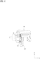
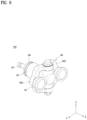
- FIG. 5 illustrates the caliper body 110 having the pad thruster 140 mounted.
- unnecessary components other than those to be described are omitted.
- at least a portion of the pad thruster 140 is inserted and positioned in the cylinder space of the caliper body 110.
- a bolt screw 143 and a movable nut 142 among the components constituting the pad thruster 140 may be partially positioned in the cylinder space.
- FIG. 6 is a perspective view of the pad thruster 140
- FIG. 7 is an exploded view of the pad thruster 140
- FIG. 8 is a side view of the pad thruster 140.
- the pad thruster 140 may move the brake pad 130 with power transmitted from the gear part.
- the pad thruster 140 includes a piston 141, a conversion assembly including the movable nut 142 and the bolt screw 143, and/or a pivotable linkage 146.
- the pad thruster 140 may be referred to as an actuator.
- the conversion assembly may represent a variety of components capable of converting the rotational motion of the gears to rectilinear motion, as well as connections between the components.
- the conversion assembly includes the bolt screw 143 and the movable nut 142 corresponding thereto.
- the conversion assembly may be seated in the cylinder space formed in the caliper body 110.
- the cylinder space may be a cylindrical space in which the movable nut 142 is movable.
- the bolt screw 143 engages with a gear connected to the motor and rotates about an axis.
- the bolt screw 143 may be oriented in an axial direction (e.g., parallel to the x-axis) at the center of the cylinder space.
- the axial direction of the bolt screw 143 is parallel to the direction in which the brake pad 130 moves (advances or retracts).
- the bolt screw 143 is positioned in the cylinder space of the caliper body 110 and rotates in place.
- the bolt screw 143 includes a spiral screw (thread) on an outer surface thereof.
- the movable nut 142 may have a screw corresponding to the screw of the bolt screw 143, and may be connected to the bolt screw 143 to move forward or backward depending on the direction of rotation of the bolt screw 143.
- the movable nut 142 connected to the bolt screw 143 may protrude out of the cylinder space or be retracted into the cylinder space while moving.
- the movable nut 142 may move along the longitudinal direction of the cylinder space.
- the movable nut 142 is formed to be long enough that the head of the movable nut 142 protrudes out of the cylinder space even when the movable nut 142 is fully inserted into the cylinder space.
- the length of the movable nut 142 may be greater than the depth of the cylinder space.
- the length L of the moving nut 142 is greater than the depth D of the cylinder space minus the thickness W of the bearing, i.e., L > (D-W).
- the pad thruster 140 may further include a bearing 144 connected to the bolt screw 143.
- the bearing 144 may include one or more bearings, and may be positioned behind the tail portion of the movable nut 142.
- the bearing 144 may include a screw bearing and may maintain the bolt screw 143 at a constant position.
- the movable nut 142 is partially located inside the cylinder space, and movement of the movable nut 142 is guided by the direction in which the cylinder space is formed.
- the movable nut 142 may be referred to as a ball screw nut, and the structure of the bolt screw 143 and the movable nut 142 may be referred to as a ball screw structure.
- the pad thruster 140 includes the pivotable linkage 146.
- the pivotable linkage 146 may be pivotably connected to the head of the movable nut 142, and the pivotable linkage 146 may pivot about the z-axis (vertical direction) as the axis of rotation.
- the pivotable linkage 146 may include a rotary portion 1461, a connecting arm 1462, and a piston retainer 1463.
- the rotary portion 1461 is connected to the movable nut 142 by a bolt 1461a.
- the head of the rotary portion 1461 and the movable nut 142 may each include an assembly hole formed in the z-axis direction (vertical direction), and the bolt 1461a may be inserted through the assembly hole in the vertical direction to connect the two components such that the components are pivotable about the axis.
- the bolt 1461a is secured to the movable nut 142, and the assembly hole in the rotary portion 1461 has a diameter slightly larger than the outer diameter of the bolt 1461a.
- the rotary portion 1461 may rotate about the bolt 1461a.
- Other arrangements may be employed by those of ordinary skill in the art as to the manner in which the rotary portion 1461 and the movable nut 142 are pivotably connected to each other.
- the rotary portion 1461 may be subjected to frictional resistance based on the fastening torque of the bolt 1461a.
- the fastening torque of bolt 1461a increases, the rotary portion 1461 and the movable nut 142 are more strongly coupled, and more friction is generated when the rotary portion 1461 rotates. Accordingly, by adjusting the fastening torque of bolt 1461a, the resistance to rotation of the rotary portion 1461 may be adjusted.
- the fastening torque of the bolt 1461a is excessively low, the pivotable linkage 146 may easily rotate, making it difficult to provide appropriate thrust to the brake pad 130.
- one of ordinary skill in the art may adjust the fastening torque of the bolt 1461a to provide appropriate resistance to rotation of the pivotable linkage 146.
- a washer may be additionally provided between the head of the bolt 1461a and the rotary portion 1461 to facilitate the relative behavior of the two components.
- a washer may also be included between the rotary portion 1461 and the head of the movable nut 142. The washer prevents foreign material from being introduced into the assembly hole and smooths the rotation of the pivotable linkage 146.
- a bush may be applied to the outer circumference of the bolt 1461a. The bush may be applied when damping is required for robustness to noise inside the assembly hole.
- the piston retainer 1463 is a component connected to the piston 141.
- the pivotable linkage 146 may include a plurality of piston retainers 1463.
- the plurality of piston retainers 1463 may be connected to a plurality of pistons 141, respectively.
- the plurality of pistons 141 may be symmetrically connected with respect to a center of a face of the brake pad 130 to transmit braking force to the brake pad 130.
- the connecting arm 1462 is a member connecting the rotary portion 1461 and the piston retainer 1463. One end of the connecting arm 1462 is connected to the rotary portion 1461, and the opposite end of the connecting arm 1462 is connected to the piston retainer 1463.
- the connecting arm 1462 is formed symmetrically about a central axis about which the rotary portion 1461 rotates. Specifically, the connecting arm 1462 may be formed symmetrically with respect to an xz-plane having the axis of rotation of the rotary portion 1461. In other words, the connecting arm 1462 may be formed symmetrically with respect to an imaginary vertical plane (i.e., the xz-plane) that passes through the center of the brake pad 130 and is perpendicular to the face of the brake pad 130. Further, the connecting arm 1462 may be formed symmetrically with respect to the vertical plane (i.e., the xz-plane) that includes the axis of rotation of the bolt screw 143 and the axis of rotation of the rotary portion 1461.
- the connecting arm 1462 may be formed symmetrically with respect to an imaginary horizontal plane (i.e., the xy-plane) that includes the center of the brake pad 130 and is perpendicular to the face of the brake pad 130.
- the connecting arm 1462 may be symmetrically formed with respect to a horizontal plane (i.e., the xy-plane) that includes the axis of rotation of the bolt screw 143 and is perpendicular to the axis of rotation of the rotary portion 1461.
- the plurality of pistons 141 may be symmetrically connected to the pivotable linkage 146, according to the shape of the connecting arm 1462. Thus, the plurality of pistons 141 may exert a uniform force against the face of the brake pad 130.
- the specific shape of the connecting arm 1462 may be appropriately modified by one of ordinary skill in the art. Once the positions of the plurality of pistons 141 connected to the brake pad 130 to thrust the brake pad 130 are designed, the positions of the plurality of piston retainers 1463 connected to each of the plurality of pistons 141 are defined, and the connecting arm 1462 is formed to connect the plurality of piston retainers 1463 to the rotary portion 1461.
- the connecting arm 1462 is formed of a member having an appropriate strength in consideration of the force that presses the brake pad 130.
- the piston 141 is connected to the brake pad 130 at one end and to the piston retainer 1463 at an opposite end to transmit the movement of the movable nut 142 to the brake pad 130.
- the shape of the piston 141 may include a cylindrical shape with an open end, and may be connected to the piston retainer 1463 via the open end.
- the piston retainer 1463 is connected to the piston 141 by a protruding portion thereof inserted through the open end of the piston 141.
- the protruding portion of the piston retainer 1463 may include a curved surface
- the piston 141 may include a curved surface corresponding to one side close to the protruding portion of the piston retainer 1463.
- the corresponding side of the piston 141 may include a concave curved surface.
- the curved surface of the piston retainer 1463 and the curved surface of the piston 141 may contact each other face to face.
- the curved surface of the piston retainer 1463 and the curved surface of the piston 141 may be spaced from each other by a predetermined distance in a neutral state.
- the piston 141 may be capable of flexible movement within the range allowed by the predetermined distance.
- the axial direction of the piston 141 may be slightly inclined with respect to the axial direction of the movable nut 142. Accordingly, the piston 141 may have flexibility while maintaining connectivity with the piston retainer 1463.
- a seal part 148 is configured to seal the gap between the piston 141 and the piston retainer 1463.
- the seal part 148 prevents foreign substances from being introduced into the piston 141.
- the piston retainer 1463 includes a first groove formed along the circumference of the protruding portion, and the piston 141 includes a second groove on an inner surface thereof that corresponds in position to the first groove.
- the first groove and the second groove face each other.
- the first groove and the second groove provide a space in which the seal part 148 may be positioned.
- the seal part 148 may be positioned in the space defined by the first groove of the piston retainer 1463 and the second groove of the piston 141.
- the seal part 148 may have a shape formed according to the space defined by the first groove of the piston retainer 1463 and the second groove of the piston 141, and may include a ring shape.
- the shape of the seal part 148 may vary depending on the cross-sectional shape of the piston retainer 1463. Further, the cross-section of the seal part 148 may have a rectangular or circular shape, and the groove shape of the first groove and the second groove may change according to the shape of the cross section of the seal part 148.
- the seal part 148 may include parts and materials commonly used for sealing. The seal part 148 seals the gap between the piston retainer 1463 and the piston 141 while connecting the piston retainer 1463 and the piston 141 such that the piston retainer 1463 and the piston 141 are not separated from each other.
- piston retainer 1463 and the piston 141 may be connected by caulking.
- a boot 147 closes the gap between the outer wall surrounding the cylinder space in the caliper body 110 and the outer surface of the movable nut 142 to prevent the introduction of foreign substances from the outside.
- the caliper body 110 includes a third groove formed along the edge of the opening in the cylinder space, and the movable nut 142 includes a fourth groove formed along the outer circumferential surface thereof.
- the fourth groove is positioned outside of the cylinder space.
- One end of the boot 147 is inserted and secured in the third groove, and the opposite end of the boot 147 is inserted and secured in the fourth groove.
- the boot 147 is provided with a plurality of layered folds to be flexibly deformed according to changes in the position of the movable nut 142 and to prevent foreign substances from entering the gap between the movable nut 142 and the wall of the cylinder space.
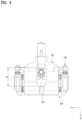
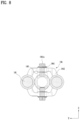
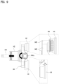
- FIG. 9 is a top plan view and partially enlarged view of the pad thruster 140.
- the movable nut 142 is moved rectilinearly by rotation of the bolt screw 143, and the pivotable linkage 146 and the movable nut 142 are pivotably connected by the bolt 1461a.
- the pivotable linkage 146 may be rotated to bring the face of the brake pad 130 into uniform contact with the face of the brake disk.
- the vertical distance c between the plane including the front surface of the piston 141 and the plane which includes the end of the head of the movable nut 142 and is perpendicular to the axis of rotation of the bolt screw 143 is set to be greater than or equal to 2 mm.
- the normal distance from the imaginary plane including the front surfaces of the plurality of pistons 141 in the neutral state to the end of the head of the movable nut 142 is greater than or equal to 2 mm. Accordingly, even when the brake pad 130 is inclined by a predetermined angle according to rotation of the pivotable linkage 146, the rear surface of the brake pad 130 does not contact the head of the movable nut 142.
- the caliper body 110 may include a heat dissipation hole 112.
- the heat dissipation hole 112 is a through-hole formed through the caliper body 110 to allow heat dissipated from the bolt 1461a to be easily transferred to the outside.
- the width of the heat dissipation hole 112 may be defined as a, and the length of the heat dissipation hole 112 may be defined as b.
- a is at least greater than the outermost diameter of the head of the bolt 1461a
- b is greater than the sum of the outermost diameter of the head of the bolt 1461a and two times the allowable amount of wear of the brake pad 130, i.e., b > outermost diameter of the head of the bolt + (allowable amount of wear * 2).
- the heat dissipation hole 112 is positioned above the bolt 1461a, and may be disposed in a direction parallel to the direction in which the bolt 1461a moves.
- the caliper body 110 may include a heat dissipation hole 112 that is a through-hole having a width greater than the width of the bolt 1461a and a length greater than the sum of two times the allowable amount of wear of the brake pad 130 and the width of the bolt 1461a, wherein the heat dissipation hole 112 may be positioned above the bolt 1461a and formed along the direction of movement of the bolt 1461a.
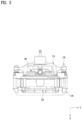
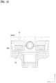
- FIG. 10 is a cross-sectional view of a pad thruster 140 mounted in the caliper body 110.
- the caliper body 110 further includes a stopper 114 configured to prevent the pivotable linkage 146 from rotating beyond a predetermined angle in the neutral state.
- the stopper 114 protrudes from a surface of the caliper body 110 located behind the piston retainer 1463. Accordingly, when the pivotable linkage 146 is rotated by a predetermined angle and the piston retainer 1463 comes into contact with the stopper 114, the pivotable linkage 146 is not allowed to rotate beyond the angle.
- the piston retainer 1463 may include a groove into which at least a portion of the stopper 114 may be inserted.
- the brake pad 130 is subjected to an external force that causes the brake pad 130 to tilt due to the tilt of the unevenly worn surface of the pad when applying pressure to the brake disk.
- the brake pad 130 may be slightly tilted, and therefore the magnitude of the external force applied to the piston 141 or the movable nut 142 may be greatly reduced, and the possibility of breakage may be reduced.
- the pivotable linkage 146 is rotatable on the head of the movable nut 142. Accordingly, when multiple pistons 141 are used, the difference in the applied pressure between the pistons 141 may be minimized. Therefore, even when there is an issue such as an orientation error of the movable nut due to uneven wear of the brake pad 130 or manufacturing tolerances, pressure may be evenly applied to the brake pad 130 due to the pivotable linkage 146.
- the gap between the piston retainer 1463 and the piston 141 may improve the return performance of the brake pad 130 and prevent the piston 141 from bumping due to vibration of the vehicle. Accordingly, the noise from the device may be reduced and durability of the device may be improved.
- the brake device 100 is capable of integrally moving multiple pistons by one conversion assembly, the manufacturing cost may be reduced, the weight may be reduced, and the surface pressure of the brake pad 130 may be improved.
- the brake device 100 may improve the surface pressure of the brake pad 130 by applying multiple pistons to the single brake pad 130. Since the size of the piston can be reduced regardless of the caliper body 110, the surface pressure of the brake pad 130 may be improved to be uniform by applying multiple pistons.
- the likelihood of breakage of the pistons of a brake device may be reduced.
- the surface pressure exerted on the brake pads may be improved.
- the utilization of a brake pad connected to multiple pistons may be increased.
Landscapes
- Engineering & Computer Science (AREA)
- General Engineering & Computer Science (AREA)
- Mechanical Engineering (AREA)
- Transportation (AREA)
- Braking Arrangements (AREA)
- Braking Systems And Boosters (AREA)
Applications Claiming Priority (1)
| Application Number | Priority Date | Filing Date | Title |
|---|---|---|---|
| KR1020230050287A KR20240153843A (ko) | 2023-04-17 | 2023-04-17 | 브레이크 장치 |
Publications (2)
| Publication Number | Publication Date |
|---|---|
| EP4450843A1 true EP4450843A1 (de) | 2024-10-23 |
| EP4450843B1 EP4450843B1 (de) | 2025-12-31 |
Family
ID=87158324
Family Applications (1)
| Application Number | Title | Priority Date | Filing Date |
|---|---|---|---|
| EP23183660.2A Active EP4450843B1 (de) | 2023-04-17 | 2023-07-05 | Bremsvorrichtung |
Country Status (5)
| Country | Link |
|---|---|
| US (1) | US12607241B2 (de) |
| EP (1) | EP4450843B1 (de) |
| JP (1) | JP2024153526A (de) |
| KR (1) | KR20240153843A (de) |
| CN (1) | CN118815847A (de) |
Families Citing this family (1)
| Publication number | Priority date | Publication date | Assignee | Title |
|---|---|---|---|---|
| US12435765B2 (en) * | 2022-05-27 | 2025-10-07 | Hyundai Mobis Co., Ltd. | Brake device and vehicle having the same |
Citations (11)
| Publication number | Priority date | Publication date | Assignee | Title |
|---|---|---|---|---|
| JP2010025222A (ja) * | 2008-07-18 | 2010-02-04 | Nissin Kogyo Co Ltd | 電動式ディスクブレーキ装置 |
| US8205725B2 (en) * | 2008-05-30 | 2012-06-26 | Hitachi, Ltd. | Electric disk brake |
| US20200361437A1 (en) * | 2017-11-24 | 2020-11-19 | Foundation Brakes France | Electromechanical-type disc brake caliper comprising two mechanical actuators to compensate for an uneven wearing of the one same brake pad |
| US11131354B1 (en) * | 2020-03-30 | 2021-09-28 | ZF Active Safety US Inc. | Electromechanical brake system including a force application apparatus |
| US11339842B2 (en) * | 2019-03-26 | 2022-05-24 | Akebono Brake Industry Co., Ltd. | Brake system with torque distributing assembly |
| US20220266808A1 (en) * | 2019-07-31 | 2022-08-25 | Brembo S.P.A | Hydraulic and electromechanical service and parking disc brake |
| US20220297660A1 (en) * | 2021-03-16 | 2022-09-22 | Mando Corporation | Electric parking brake |
| US11518359B2 (en) * | 2019-09-20 | 2022-12-06 | Hyundai Mobis Co., Ltd. | Brake apparatus for vehicle |
| US20230036745A1 (en) * | 2021-07-29 | 2023-02-02 | Akebono Brake Industry Co., Ltd. | Motor gear unit for disc brake apparatus and disc brake apparatus |
| DE102022120333A1 (de) * | 2021-08-11 | 2023-02-16 | Mando Corporation | Elektromechanische bremse und fahrzeug, das diese umfasst |
| KR20230050287A (ko) | 2013-07-10 | 2023-04-14 | 가부시키가이샤 한도오따이 에네루기 켄큐쇼 | 반도체 장치, 구동 회로, 및 표시 장치 |
Family Cites Families (19)
| Publication number | Priority date | Publication date | Assignee | Title |
|---|---|---|---|---|
| US4804073A (en) * | 1980-12-23 | 1989-02-14 | Allied-Signal Inc. | Electrically operated disc brake with back-off protector |
| NL1009584C2 (nl) * | 1998-07-07 | 2000-01-10 | Skf Eng & Res Centre Bv | Actuator voorzien van een centrale steun, alsmede remklauw met een dergelijke actuator. |
| US7188710B2 (en) * | 2004-02-09 | 2007-03-13 | Delphi Technologies, Inc. | Hydraulic brake actuator comprising electrically actuable lock for park brake |
| DE102009013005C5 (de) * | 2009-03-13 | 2013-05-02 | Knorr-Bremse Systeme für Nutzfahrzeuge GmbH | Doppelkolben-Scheibenbremse |
| DE102011103823A1 (de) * | 2011-06-09 | 2012-12-13 | Knorr-Bremse Systeme für Nutzfahrzeuge GmbH | Mehrfachkolben-Scheibenbremse |
| US9145120B2 (en) * | 2011-09-09 | 2015-09-29 | Performance Friction Corporation | Sliding caliper parking brake having positive brake pad retraction |
| DE102012209341B4 (de) * | 2012-06-02 | 2024-09-19 | Gustav Magenwirth Gmbh & Co. Kg | Bremszange |
| US9353811B2 (en) * | 2013-11-13 | 2016-05-31 | Akebono Brake Industry Co., Ltd | Electric park brake for a multiple piston caliper |
| US9587692B2 (en) * | 2015-04-01 | 2017-03-07 | Akebono Brake Industry Co., Ltd | Differential for a parking brake assembly |
| KR102460852B1 (ko) * | 2015-12-14 | 2022-11-01 | 현대모비스 주식회사 | 전동 브레이크 장치 |
| KR102502525B1 (ko) * | 2016-02-03 | 2023-02-22 | 에이치엘만도 주식회사 | 전자식 디스크 브레이크 |
| US9828059B2 (en) * | 2016-04-12 | 2017-11-28 | Shimano, Inc. | Bicycle disc brake caliper with brake pad spacer |
| US20190063527A1 (en) * | 2017-08-29 | 2019-02-28 | Akebono Brake Industry Co., Ltd | Brake assembly with motor brake |
| KR102022403B1 (ko) * | 2018-01-17 | 2019-09-18 | 현대모비스 주식회사 | 차량용 브레이크 장치 |
| US11655867B2 (en) * | 2018-08-21 | 2023-05-23 | Akebono Brake Industry Co., Ltd | Disc brake system |
| CN112238851B (zh) * | 2019-07-16 | 2023-03-14 | 现代摩比斯株式会社 | 用于车辆的驻车制动设备 |
| DE102021101088A1 (de) * | 2020-01-22 | 2021-07-22 | Mando Corporation | Reibungsbremssystem für ein Fahrzeug |
| US11554766B2 (en) * | 2021-03-17 | 2023-01-17 | ZF Active Safety US Inc. | Hydraulically assisted electric parking brake |
| US11964641B2 (en) * | 2021-07-13 | 2024-04-23 | ZF Active Safety US Inc. | Electronic parking brake |
-
2023
- 2023-04-17 KR KR1020230050287A patent/KR20240153843A/ko active Pending
- 2023-06-16 US US18/210,942 patent/US12607241B2/en active Active
- 2023-07-04 JP JP2023109899A patent/JP2024153526A/ja active Pending
- 2023-07-05 EP EP23183660.2A patent/EP4450843B1/de active Active
- 2023-07-20 CN CN202310895848.4A patent/CN118815847A/zh active Pending
Patent Citations (11)
| Publication number | Priority date | Publication date | Assignee | Title |
|---|---|---|---|---|
| US8205725B2 (en) * | 2008-05-30 | 2012-06-26 | Hitachi, Ltd. | Electric disk brake |
| JP2010025222A (ja) * | 2008-07-18 | 2010-02-04 | Nissin Kogyo Co Ltd | 電動式ディスクブレーキ装置 |
| KR20230050287A (ko) | 2013-07-10 | 2023-04-14 | 가부시키가이샤 한도오따이 에네루기 켄큐쇼 | 반도체 장치, 구동 회로, 및 표시 장치 |
| US20200361437A1 (en) * | 2017-11-24 | 2020-11-19 | Foundation Brakes France | Electromechanical-type disc brake caliper comprising two mechanical actuators to compensate for an uneven wearing of the one same brake pad |
| US11339842B2 (en) * | 2019-03-26 | 2022-05-24 | Akebono Brake Industry Co., Ltd. | Brake system with torque distributing assembly |
| US20220266808A1 (en) * | 2019-07-31 | 2022-08-25 | Brembo S.P.A | Hydraulic and electromechanical service and parking disc brake |
| US11518359B2 (en) * | 2019-09-20 | 2022-12-06 | Hyundai Mobis Co., Ltd. | Brake apparatus for vehicle |
| US11131354B1 (en) * | 2020-03-30 | 2021-09-28 | ZF Active Safety US Inc. | Electromechanical brake system including a force application apparatus |
| US20220297660A1 (en) * | 2021-03-16 | 2022-09-22 | Mando Corporation | Electric parking brake |
| US20230036745A1 (en) * | 2021-07-29 | 2023-02-02 | Akebono Brake Industry Co., Ltd. | Motor gear unit for disc brake apparatus and disc brake apparatus |
| DE102022120333A1 (de) * | 2021-08-11 | 2023-02-16 | Mando Corporation | Elektromechanische bremse und fahrzeug, das diese umfasst |
Also Published As
| Publication number | Publication date |
|---|---|
| KR20240153843A (ko) | 2024-10-24 |
| JP2024153526A (ja) | 2024-10-29 |
| US12607241B2 (en) | 2026-04-21 |
| CN118815847A (zh) | 2024-10-22 |
| US20240344576A1 (en) | 2024-10-17 |
| EP4450843B1 (de) | 2025-12-31 |
Similar Documents
| Publication | Publication Date | Title |
|---|---|---|
| US10883582B2 (en) | Ball screw apparatus | |
| KR100681805B1 (ko) | 오정렬 보상부를 구비하는 작동기 | |
| US10899332B2 (en) | Electric caliper brake | |
| US6073732A (en) | Disc brake device for motor vehicles | |
| EP4450843A1 (de) | Bremsvorrichtung | |
| US20240060551A1 (en) | Linear actuator having wobble joint | |
| WO2023017840A1 (ja) | 電動制動装置 | |
| US20050150729A1 (en) | Disc brake with electrically operated adjustment device | |
| US20240328468A1 (en) | Brake device | |
| US20240191760A1 (en) | Brake device and assembly method thereof | |
| US20240352986A1 (en) | Brake device | |
| US20250222911A1 (en) | Brake device and vehicle including the same | |
| EP4575260A1 (de) | Bremssattel | |
| US20250035171A1 (en) | Brake device and vehicle including the same | |
| US20240247697A1 (en) | Ball and nut assembly | |
| KR20240088273A (ko) | 브레이크 장치 | |
| US20260008445A1 (en) | Electric braking device | |
| WO2024162272A1 (ja) | 電動制動装置 | |
| KR20240178982A (ko) | 전기 기계식 브레이크 | |
| JP2024108148A (ja) | 電動制動装置 | |
| KR20240124129A (ko) | 브레이크 장치 | |
| CN121993520A (zh) | 电子机械制动卡钳、制动系统及车辆 | |
| CN120576218A (zh) | 丝杠传动装置、电子机械制动器和集成制动控制系统 | |
| CN119099574A (zh) | 一种用于线控制动系统的电子机械制动器结构 |
Legal Events
| Date | Code | Title | Description |
|---|---|---|---|
| PUAI | Public reference made under article 153(3) epc to a published international application that has entered the european phase |
Free format text: ORIGINAL CODE: 0009012 |
|
| STAA | Information on the status of an ep patent application or granted ep patent |
Free format text: STATUS: THE APPLICATION HAS BEEN PUBLISHED |
|
| AK | Designated contracting states |
Kind code of ref document: A1 Designated state(s): AL AT BE BG CH CY CZ DE DK EE ES FI FR GB GR HR HU IE IS IT LI LT LU LV MC ME MK MT NL NO PL PT RO RS SE SI SK SM TR |
|
| STAA | Information on the status of an ep patent application or granted ep patent |
Free format text: STATUS: REQUEST FOR EXAMINATION WAS MADE |
|
| 17P | Request for examination filed |
Effective date: 20250415 |
|
| GRAP | Despatch of communication of intention to grant a patent |
Free format text: ORIGINAL CODE: EPIDOSNIGR1 |
|
| STAA | Information on the status of an ep patent application or granted ep patent |
Free format text: STATUS: GRANT OF PATENT IS INTENDED |
|
| INTG | Intention to grant announced |
Effective date: 20250804 |
|
| GRAS | Grant fee paid |
Free format text: ORIGINAL CODE: EPIDOSNIGR3 |
|
| GRAA | (expected) grant |
Free format text: ORIGINAL CODE: 0009210 |
|
| STAA | Information on the status of an ep patent application or granted ep patent |
Free format text: STATUS: THE PATENT HAS BEEN GRANTED |
|
| P01 | Opt-out of the competence of the unified patent court (upc) registered |
Free format text: CASE NUMBER: UPC_APP_0010862_4450843/2025 Effective date: 20251023 |
|
| AK | Designated contracting states |
Kind code of ref document: B1 Designated state(s): AL AT BE BG CH CY CZ DE DK EE ES FI FR GB GR HR HU IE IS IT LI LT LU LV MC ME MK MT NL NO PL PT RO RS SE SI SK SM TR |
|
| REG | Reference to a national code |
Ref country code: CH Ref legal event code: F10 Free format text: ST27 STATUS EVENT CODE: U-0-0-F10-F00 (AS PROVIDED BY THE NATIONAL OFFICE) Effective date: 20251231 Ref country code: GB Ref legal event code: FG4D |
|
| REG | Reference to a national code |
Ref country code: DE Ref legal event code: R096 Ref document number: 602023010296 Country of ref document: DE |
|
| REG | Reference to a national code |
Ref country code: IE Ref legal event code: FG4D |
|
| REG | Reference to a national code |
Ref country code: LT Ref legal event code: MG9D |
|
| PG25 | Lapsed in a contracting state [announced via postgrant information from national office to epo] |
Ref country code: NO Free format text: LAPSE BECAUSE OF FAILURE TO SUBMIT A TRANSLATION OF THE DESCRIPTION OR TO PAY THE FEE WITHIN THE PRESCRIBED TIME-LIMIT Effective date: 20260331 |
|
| PG25 | Lapsed in a contracting state [announced via postgrant information from national office to epo] |
Ref country code: FI Free format text: LAPSE BECAUSE OF FAILURE TO SUBMIT A TRANSLATION OF THE DESCRIPTION OR TO PAY THE FEE WITHIN THE PRESCRIBED TIME-LIMIT Effective date: 20251231 Ref country code: HR Free format text: LAPSE BECAUSE OF FAILURE TO SUBMIT A TRANSLATION OF THE DESCRIPTION OR TO PAY THE FEE WITHIN THE PRESCRIBED TIME-LIMIT Effective date: 20251231 |
|
| PG25 | Lapsed in a contracting state [announced via postgrant information from national office to epo] |
Ref country code: RS Free format text: LAPSE BECAUSE OF FAILURE TO SUBMIT A TRANSLATION OF THE DESCRIPTION OR TO PAY THE FEE WITHIN THE PRESCRIBED TIME-LIMIT Effective date: 20260331 |
|
| PG25 | Lapsed in a contracting state [announced via postgrant information from national office to epo] |
Ref country code: LV Free format text: LAPSE BECAUSE OF FAILURE TO SUBMIT A TRANSLATION OF THE DESCRIPTION OR TO PAY THE FEE WITHIN THE PRESCRIBED TIME-LIMIT Effective date: 20251231 |