EP4450860A1 - Dispositif de remplacement de pipeline et procédé d'utilisation du dispositif de remplacement de pipeline - Google Patents
Dispositif de remplacement de pipeline et procédé d'utilisation du dispositif de remplacement de pipeline Download PDFInfo
- Publication number
- EP4450860A1 EP4450860A1 EP23207042.5A EP23207042A EP4450860A1 EP 4450860 A1 EP4450860 A1 EP 4450860A1 EP 23207042 A EP23207042 A EP 23207042A EP 4450860 A1 EP4450860 A1 EP 4450860A1
- Authority
- EP
- European Patent Office
- Prior art keywords
- shell
- pipeline
- replacement device
- cutting
- mounting plate
- Prior art date
- Legal status (The legal status is an assumption and is not a legal conclusion. Google has not performed a legal analysis and makes no representation as to the accuracy of the status listed.)
- Pending
Links
Images


Classifications
-
- E—FIXED CONSTRUCTIONS
- E03—WATER SUPPLY; SEWERAGE
- E03F—SEWERS; CESSPOOLS
- E03F3/00—Sewer pipe-line systems
- E03F3/06—Methods of, or installations for, laying sewer pipes
-
- F—MECHANICAL ENGINEERING; LIGHTING; HEATING; WEAPONS; BLASTING
- F16—ENGINEERING ELEMENTS AND UNITS; GENERAL MEASURES FOR PRODUCING AND MAINTAINING EFFECTIVE FUNCTIONING OF MACHINES OR INSTALLATIONS; THERMAL INSULATION IN GENERAL
- F16L—PIPES; JOINTS OR FITTINGS FOR PIPES; SUPPORTS FOR PIPES, CABLES OR PROTECTIVE TUBING; MEANS FOR THERMAL INSULATION IN GENERAL
- F16L55/00—Devices or appurtenances for use in, or in connection with, pipes or pipe systems
- F16L55/16—Devices for covering leaks in pipes or hoses, e.g. hose-menders
- F16L55/162—Devices for covering leaks in pipes or hoses, e.g. hose-menders from inside the pipe
- F16L55/165—Devices for covering leaks in pipes or hoses, e.g. hose-menders from inside the pipe a pipe or flexible liner being inserted in the damaged section
- F16L55/1658—Devices for covering leaks in pipes or hoses, e.g. hose-menders from inside the pipe a pipe or flexible liner being inserted in the damaged section the old pipe being ruptured prior to insertion of a new pipe
-
- E—FIXED CONSTRUCTIONS
- E03—WATER SUPPLY; SEWERAGE
- E03F—SEWERS; CESSPOOLS
- E03F3/00—Sewer pipe-line systems
- E03F3/06—Methods of, or installations for, laying sewer pipes
- E03F2003/065—Refurbishing of sewer pipes, e.g. by coating, lining
-
- Y—GENERAL TAGGING OF NEW TECHNOLOGICAL DEVELOPMENTS; GENERAL TAGGING OF CROSS-SECTIONAL TECHNOLOGIES SPANNING OVER SEVERAL SECTIONS OF THE IPC; TECHNICAL SUBJECTS COVERED BY FORMER USPC CROSS-REFERENCE ART COLLECTIONS [XRACs] AND DIGESTS
- Y02—TECHNOLOGIES OR APPLICATIONS FOR MITIGATION OR ADAPTATION AGAINST CLIMATE CHANGE
- Y02P—CLIMATE CHANGE MITIGATION TECHNOLOGIES IN THE PRODUCTION OR PROCESSING OF GOODS
- Y02P70/00—Climate change mitigation technologies in the production process for final industrial or consumer products
- Y02P70/10—Greenhouse gas [GHG] capture, material saving, heat recovery or other energy efficient measures, e.g. motor control, characterised by manufacturing processes, e.g. for rolling metal or metal working
Definitions
- the present invention relates to the technical field of underground drainage pipeline replacement, in particular relates to a pipeline replacement device and a method for using the pipeline replacement device.
- the excavation type method is to excavate the land, expose the pipes, and then replace the old pipes.
- this type of method would have a significant impact on surrounding residents and traffic, and may also cause damage to cables or other pipelines during the excavation process.
- the non-excavation type method is to respectively arrange an originating well and a receiving well at the starting and ending positions of replacement work, and lower the pipeline replacement device into the originating well.
- the pipeline replacement device is used to break old pipelines and lay new pipelines at corresponding underground positions, thereby reducing the impact on surrounding residents and traffic.
- the existing pipeline replacement devices use pneumatic picks or tooth wheels to forcefully break the pipe wall when breaking old reinforced concrete pipelines, resulting in poor breaking effect, long working time, and loud working noise. And the cutting tools are extremely prone to wear and tear, and thus require regular replacement, which increases working costs.
- a technical problem to be solved by the present invention is how to overcome the defects of poor breaking effect, long working time, loud working noise, and the need for regular replacement of cutting tools when a reinforced concrete pipeline replacement device in the prior art needs to use a pneumatic pick or a tooth wheel to forcefully break the pipe wall, thereby providing a pipeline replacement device with low working noise, good cutting effect, short working time and no need for regular replacement of a cutting mechanism, and a method for using the pipeline replacement device.
- the present invention provides a pipeline replacement device that comprises:
- the water jet cutting component comprises at least one water jet rotatable nozzle and a plurality of water jet fixed nozzles, wherein the plurality of water jet fixed nozzles are spaced apart in a circumferential direction around the shell, the waterjet rotatable nozzle is arranged on one side of the waterjet fixed nozzles away from the shell.
- the cutting mechanism further comprises a first mounting plate, one end of the first mounting plate is connected to an inner wall of the shell, an opposite end of the first mounting plate extends out of the shell and is provided with the waterjet cutting component.
- the waste transportation mechanism comprises a receiving member, a gripping member and a transportation member
- the receiving member is arranged above the first mounting plate, and a receiving gap is formed between an upper surface of the receiving member and a second mounting plate fixedly arranged on the inner wall of the shell, and a waste inlet opening is provided at ends of both the receiving member and the second mounting plate near the waterjet cutting component
- the gripping member is arranged near the rear end of the shell and is fixedly connected to the inner wall of the shell
- the transportation member is arranged at bottom of the shell.
- the pipeline replacement device further comprises a soil scraping mechanism, which comprises a driving member, a transmission component, and a cutter disk, wherein the driving member is arranged at the bottom of the shell, a driving end of the driving member is connected to a power input end of the transmission component, and a power output end of the transmission component is connected to the cutter disk.
- a soil scraping mechanism which comprises a driving member, a transmission component, and a cutter disk, wherein the driving member is arranged at the bottom of the shell, a driving end of the driving member is connected to a power input end of the transmission component, and a power output end of the transmission component is connected to the cutter disk.
- the transmission component comprises a first transmission gear and a second transmission gear that are connected to each other in a meshing manner, wherein the first transmission gear is connected to the driving end of the driving member, the second transmission gear is sleeved on the second mounting plate, and the cutter disk is fixedly connected to an end surface of the second transmission gear.
- the cutter disk is provided with a scraper tooth component, which comprises a plurality of first scraper teeth and a plurality of second scraper teeth spaced apart in a circumferential direction, and the second scraper teeth are arranged near an outer edge of the cutter disk.
- a scraper tooth component which comprises a plurality of first scraper teeth and a plurality of second scraper teeth spaced apart in a circumferential direction, and the second scraper teeth are arranged near an outer edge of the cutter disk.
- the pipeline replacement device further comprises a mud water treatment mechanism, which comprises a mud inlet opening, a partition plate, a water inlet pipe, and a mud water discharge pipe, wherein an end surface of the cutter disk is provided with a plurality of mud inlet openings, and the partition plate is sleeved on the second mounting plate, and the partition plate is arranged to be spaced apart from the cutter disk, wherein the cutter disk, the partition plate, the shell and the second mounting plate together enclose a mud water accommodation chamber, and the partition plate is provided with an water inlet opening and a mud water outlet opening, wherein the water inlet opening and the mud water outlet opening are respectively connected to the water inlet pipe and the mud water discharge pipe.
- a mud water treatment mechanism which comprises a mud inlet opening, a partition plate, a water inlet pipe, and a mud water discharge pipe, wherein an end surface of the cutter disk is provided with a plurality of mud inlet openings, and the partition plate is
- the shell comprises a front shell part and a rear shell part that are connected to each other in a plugging manner, one side of the front shell part near the rear shell part and one side of the rear shell part near the front shell part are both provided with an annular plate, wherein an adjustment mechanism for adjusting a forward travelling direction of the shell is arranged between the two annular plates on the front shell part and the rear shell part, and three micro-inertial measurement units are arranged on an inner wall of the front shell part.
- a method for using a pipeline replacement device which is applied to the above-mentioned pipeline replacement device, the method comprises the following steps:
- orientational or locational relationships indicated by terms such as “center”, “up”, “down”, “left”, “right”, “vertical”, “horizontal”, “inside”, and “outside” are based on orientational or locational relationships shown in the accompanying drawings, and are only used to facilitate description of the present invention and simplify description, but are not used to indicate or imply that the apparatuses or elements referred to must have a specific orientation or must be constructed and operated in a specific orientation, and therefore, cannot be understood as a limitation to the present invention.
- the terms such as “first”, “second”, and “third” are used only for description, but are not intended to indicate or imply relative importance.
- this pipeline replacement device can be applied to cut old underground concrete drainage pipelines and replace them with new drainage pipelines. Moreover, this pipeline replacement device does not require preheating during cutting and can directly cut old pipelines, and therefore has shorter working time, high efficiency, and does not require regular replacement of its cutting mechanism.
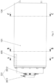
- the above-mentioned pipeline replacement device comprises: a shell 1, a cutting mechanism, a waste transportation mechanism and a jacking mechanism 4.
- the shell 1 is cylindrical, and comprises a front shell part 101 and a rear shell part 102, which are connected to each other in a plugging manner and sealed with rubber sealing rings.
- the front end of the shell 1 is on the left side, and the rear end of the shell 1 is on the right side.
- the adjustment mechanism is a plurality of deviation correction jacks 104 arranged in a circumferential direction.
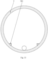
- three micro-inertial measurement units 105 are arranged on an inner wall of the front shell part 101, and the three micro-inertial measurement units 105 are located in the same vertical cross-section. The position of the shell 1 can be measured by the micro-inertial measurement units 105, so as to calculate a deviation from the position of the old pipeline 10, which facilitates controlling the deviation correction jacks 104 to correct the deviation.
- the cutting mechanism comprises a water jet cutting component 201 arranged on a front end of the shell 1, the water jet cutting component 201 comprises at least one waterjet rotatable nozzle 2011 and a plurality of water jet fixed nozzles 2012, wherein the plurality of water jet fixed nozzles 2012 are spaced apart in a circumferential direction around the shell 1, the waterjet rotatable nozzle 2011 is arranged on one side of the waterjet fixed nozzles 2012 away from the shell 1.
- the water jet cutting component 201 comprises one waterjet rotatable nozzle 2011 and six water jet fixed nozzles 2012, the water-jetting direction of the water jet fixed nozzle 2012 is along the radial direction of the shell 1, and the water-jetting direction of the water jet rotatable nozzle 2011 tilts towards the side of the water jet fixed nozzles 2012.
- the cutting mechanism further comprises a first mounting plate 202, one end of the first mounting plate 202 is connected to an inner wall of the shell 1, an opposite end of the first mounting plate 202 extends out of the shell 1 and is provided with the water jet cutting component 201.
- the first mounting plate 202 is cylindrical and arranged coaxially with the shell 1.
- One end of the first mounting plate 202 is fixedly connected to the inner wall of the shell 1 through position-limiting rods 203 and position-limiting rib plates 204, and an opposite end of the first mounting plate 202 extends out of the shell 1.
- Six mounting holes are arranged on the end of the first mounting plate 202 which extends out of the shell 1 and are used to mount the six water jet fixed nozzles 2012.
- a rotatable rotating seat is also arranged at this end for mounting the waterjet rotatable nozzle 2011.
- the rotating seat drives the waterjet rotatable nozzle 2011 to rotate, so that the water jet rotatable nozzle 2011 can perform circular cutting.
- this end of the first mounting plate 202 is also provided with a high-definition camera 205, which can monitor the working process and transmit real-time working images.
- the cutting mechanism also comprises an auxiliary component 206, which is located in the rear shell part 102.
- High-pressure water can be provided from the auxiliary component 206 to the water jet rotatable nozzle 2011 and the waterjet fixed nozzles 2012, and the old pipeline 10 is cut by using the high-pressure water.
- the auxiliary component 206 comprises a water storage tank, an automatic sand control device, and a high-pressure pump. As shown in Figure 11 , the automatic sand control device and the high-pressure pump are powered by a distribution box 8 located in the rear shell part 102, and a conduit connecting the automatic sand control device and the high-pressure pump to the waterjet cutting component 201 can be situated in the hollow cavity of the first mounting plate 202.
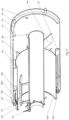
- the waste transportation mechanism is arranged inside the shell 1, wherein the waste transportation mechanism is configured to transport cut pipeline blocks from the waterjet cutting component 201 to a rear end of the shell 1. Furthermore, the waste transportation mechanism comprises a receiving member 301, a gripping member and a transportation member 303, the receiving member 301 is arranged above the first mounting plate 202, and a receiving gap is formed between an upper surface of the receiving member 301 and a second mounting plate 304 fixedly arranged on the inner wall of the shell 1, and a waste inlet opening is provided at ends of both the receiving member 301 and the second mounting plate 304 near the water jet cutting component 201.
- the receiving member 301 is an arc-shaped plate, arranged to shield above the first mounting plate 202 and fixedly connected to the first mounting plate 202 through support rods 305.
- the second mounting plate 304 is cylindrical, wherein a sealing brush 306 is arranged along the circumferential direction on the inner wall of the front end of the second mounting plate 304.
- the sealing brush 306 can form a good seal with the outer wall of the old pipeline 10.
- the second mounting plate 304 is arranged coaxially with the shell 1, and is fixedly connected to the front shell part 101 through a plurality of connection plates 307 distributed circumferentially around the inner wall of the shell 1.
- the diameter of the second mounting plate 304 is smaller than the diameter of the shell 1 and larger than the diameter of the receiving member 301, and the front end of the second mounting plate 304 extends out of the front end of the shell 1.
- the water jet cutting component 201 is located at the front end of the second mounting plate 304, that is, the cutting point is located outside the second mounting plate 304, which can cut the hard soil body and facilitate the forward movement of the shell 1.
- the old pipeline 10 enters the receiving gap between the receiving member 301 and the second mounting plate 304 from the waste inlet opening. After the old pipeline 10 is cut into pipeline blocks by the water jet cutting component 201, the pipeline blocks are scattered and fall onto the bottom of the second mounting plate 304 under the flow guide function of the receiving member 301.
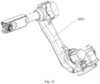
- the gripping member is arranged near the rear end of the shell 1 and is fixedly connected to the inner wall of the shell 1, and the transportation member 303 is arranged at bottom of the shell 1.
- the gripping member comprises a mechanical arm 3021 with multi degrees of freedom and a mechanical arm mounting seat 3022.
- the mechanical arm mounting seat 3022 is fixedly arranged on the inner wall of the rear shell part 102
- the mechanical arm 3021 is connected to the mechanical arm mounting seat 3022
- the transportation member 303 is a conveyor belt fixedly mounted at the bottom of the rear shell part 102, and there is space under the bottom of the conveyor belt for conduits to pass through.
- the pipeline blocks on the bottom of the second mounting plate 304 is gripped onto the conveyor belt by the mechanical arm 3021 and transported to the rear end of the shell 1 by the conveyor belt.
- a driving end of the jacking mechanism 4 is able to abut against the rear end of the shell 1 to push the shell 1 to move in a direction away from the jacking mechanism 4.
- the jacking mechanism 4 mainly provides a driving force for the forward movement of the shell 1 as well as the laying of the new pipeline 7.
- the jacking mechanism 4 comprises a plurality of hydraulic cylinders.
- the pipeline replacement device further comprises a soil scraping mechanism, which comprises a driving member 501, a transmission component 502, and a cutter disk 503, wherein the driving member 501 is arranged at the bottom of the shell 1, a driving end of the driving member 501 is connected to a power input end of the transmission component 502, and a power output end of the transmission component 502 is connected to the cutter disk 503.
- the driving member 501 is an electric motor, which is arranged at the bottom of the front shell part 101.
- the cutter disk 503 can be driven to rotate and scrape the soil under the drive of the electric motor.
- the transmission component 502 comprises a first transmission gear 5021 and a second transmission gear 5022 that are connected to each other in a meshing manner, wherein the first transmission gear 5021 is connected to the driving end of the driving member 501, the second transmission gear 5022 is sleeved on the second mounting plate 304, and the cutter disk 503 is fixedly connected to an end surface of the second transmission gear 5022.
- the first transmission gear 5021 is connected to the driving member 501 through a transmission shaft 5023, which is arranged at the bottom of the front shell part 101 and under the second mounting plate 304.
- the first transmission gear 5021 is a small gear
- the second transmission gear 5022 is a large gear.
- the cutter disk 503 is located at the front end of the shell 1, and a small clearance exists between the cutter disk 503 and the edge of the shell 1.
- the cutter disk 503 is connected to the second mounting plate 304 through a roller bearing arranged on the second mounting plate 304, and the roller bearing can restrict any axial displacement of the cutter disk 503 and meanwhile enable the cutter disk 503 to rotate circumferentially around the second mounting plate 304.
- the outer diameter of the cutter disk 503 is equal to the outer diameter of the shell 1.
- the driving member 501 drives the transmission shaft 5023 and the first transmission gear 5021 to rotate, so as to drive the second transmission gear 5022 that meshes with the first transmission gear 5021 to rotate, thereby driving the cutter disk 503 connected to the end surface of the second transmission gear 5022 to rotate.
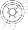
- the cutter disk 503 is provided with a scraper tooth component, which comprises a plurality of first scraper teeth 5031 and a plurality of second scraper teeth 5032 spaced apart in a circumferential direction.
- the first scraper teeth 5031 are arranged on the end surface of the cutter disk 503 and the second scraper teeth 5032 are arranged near an outer edge of the cutter disk 503, so that the cross-sectional area of scraping is slightly larger than the outer edge of the shell 1.
- the soil can be scraped by the first scraper teeth 5031 and the plurality of second scraper teeth 5032.
- the pipeline replacement device further comprises a mud water treatment mechanism, which comprises a mud inlet opening 601, a partition plate 602, a water inlet pipe 603, and a mud water discharge pipe 604, wherein an end surface of the cutter disk 503 is provided with a plurality of mud inlet openings 601, and the partition plate 602 is sleeved on the second mounting plate 304, and the partition plate 602 is arranged to be spaced apart from the cutter disk 503, wherein the cutter disk 503, the partition plate 602, the shell 1 and the second mounting plate 304 together enclose a mud water accommodation chamber 605, and the partition plate 602 is provided with an water inlet opening and a mud water outlet opening, wherein the water inlet opening is connected to the water inlet pipe 603 and the mud water outlet opening is connected to the mud water discharge pipe 604.
- a mud water treatment mechanism which comprises a mud inlet opening 601, a partition plate 602, a water inlet pipe 603, and a mud water discharge pipe 604,
- one mud inlet opening 601 is provided on both sides of each first scraper tooth 5031 on the cutter disk 503 respectively, and the mud inlet openings 601 are located on the outer side of the second transmission gear 5022.
- the water inlet opening and the mud water outlet opening are arranged at the bottom part of the partition plate 602, and the water inlet opening 603 and the mud water outlet opening 604 are also arranged at the bottom of the front shell part 101.
- the outer diameter of the new pipeline 7 is slightly smaller than the outer diameter of the shell 1.
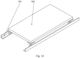
- a mounting seat 701 is provided on both sides of the bottom of the inner wall of the new pipeline 7, and a carrying mechanism can be placed on the mounting seats 701.
- the carrying mechanism comprises a trolley track 901 and a transportation trolley 902.
- the trolley track 901 is arranged on the mounting seats 701, and the transportation trolley 902 can move on the trolley track 901.
- the pipeline blocks can be transported to a position that is convenient for manual cleaning, by using the carrying mechanism to cooperate with the transportation member 303 in the rear shell part 102.
- the present embodiment further provides a method for using a pipeline replacement device, which is applied to the foregoing pipeline replacement device. Since the pipeline replacement device used has the same structure as the pipeline replacement device in the foregoing description of embodiment, it will not be repeatedly described.
- the method for using the pipeline replacement device comprises the following steps:
- the jacking mechanism 4 is turned on again to push the shell 1 and the new pipeline 7 forward.
- the above-mentioned steps are repeated, another segment of old pipeline 10 is cut and another segment of new pipeline 7 is laid, until all the old pipelines 10 have been cut and all the new pipelines 7 have been laid.
- the pipeline replacement device is disassembled and removed from the receiving work well.
- the point coordinates of the three micro-inertial measurement units 105 on the inner wall of the front shell part 101 are acquired in real time, and a 3D modeling software is used to build a 3D spatial model of the shell 1, compare it with a spatial model of the old pipeline 10, so as to calculate a deviation correction action, and the deviation correction jacks 104 is automatically controlled by issuing a command.
- the working image is constantly monitored by the high-definition camera 205, for controlling the working status of various components in time.
- Treatment is performed after the jacking is completed.
- the front and rear pipeline segments are connected to the replacement pipeline segments; the working wells are disassembled, the soil body is backfilled in a synchronous manner, and a new maintenance well is built.
- the number of water jet rotatable nozzle(s) 2011 may also be two, three, etc., and the number of water jet fixed nozzles 2012 may also be four, eight, etc.
- Embodiment 1 lies in that the positions of the water jet cutting component 201 and the second mounting plate 304, as well as the carrying mechanism arranged in the new pipeline 7, are different.
- the other structures are the same and will not be repeatedly described.
- the water jet cutting component 201 is located inside the second mounting plate 304 so as to prevent high-pressure water from disturbing the surrounding strata during cutting.
- the carrying mechanism in the new pipeline 7 comprises: slot seats 903, connection rods 904, and transportation wheels 905.
- the two slot seats 903 are respectively placed on the two mounting seats 701, and a plurality of connection rods 904 are arranged between the two slot seats 903.
- a plurality of transportation wheels 905 are mounted on each connection rod 904.
Landscapes
- Engineering & Computer Science (AREA)
- General Engineering & Computer Science (AREA)
- Mechanical Engineering (AREA)
- Health & Medical Sciences (AREA)
- Life Sciences & Earth Sciences (AREA)
- Hydrology & Water Resources (AREA)
- Public Health (AREA)
- Water Supply & Treatment (AREA)
- Excavating Of Shafts Or Tunnels (AREA)
Applications Claiming Priority (1)
| Application Number | Priority Date | Filing Date | Title |
|---|---|---|---|
| CN202310420202.0A CN116446512B (zh) | 2023-04-18 | 2023-04-18 | 一种管道更换设备及其使用方法 |
Publications (1)
| Publication Number | Publication Date |
|---|---|
| EP4450860A1 true EP4450860A1 (fr) | 2024-10-23 |
Family
ID=87128387
Family Applications (1)
| Application Number | Title | Priority Date | Filing Date |
|---|---|---|---|
| EP23207042.5A Pending EP4450860A1 (fr) | 2023-04-18 | 2023-10-31 | Dispositif de remplacement de pipeline et procédé d'utilisation du dispositif de remplacement de pipeline |
Country Status (2)
| Country | Link |
|---|---|
| EP (1) | EP4450860A1 (fr) |
| CN (1) | CN116446512B (fr) |
Citations (3)
| Publication number | Priority date | Publication date | Assignee | Title |
|---|---|---|---|---|
| US5207533A (en) * | 1990-02-01 | 1993-05-04 | Gaz De France | Process and device for replacing an underground pipe |
| EP0411278B1 (fr) * | 1989-08-02 | 1993-10-13 | Tracto-Technik Paul Schmidt, Maschinenfabrik Kg | Procédé et dispositif pour la destruction d'une conduite enterrée |
| US20150196989A1 (en) * | 2014-01-15 | 2015-07-16 | Flow International Corporation | High-pressure waterjet cutting head systems, components and related methods |
Family Cites Families (5)
| Publication number | Priority date | Publication date | Assignee | Title |
|---|---|---|---|---|
| DE3819567A1 (de) * | 1988-06-09 | 1989-12-14 | Gewerk Eisenhuette Westfalia | Arbeitskopf fuer den rohrvorpressbetrieb, insbesondere mit abfoerderung des haufwerks mittels eines transportcontainers |
| CN104482296B (zh) * | 2014-10-31 | 2016-12-07 | 九峰海洋生态建设集团有限公司 | 一种管道更换顶管机 |
| CN112031788B (zh) * | 2020-09-27 | 2022-03-22 | 中铁工程装备集团有限公司 | 一种水射流破拆、扩径掘进机及其施工方法 |
| CN216520284U (zh) * | 2022-01-05 | 2022-05-13 | 徐州迈科特装备制造有限公司 | 一种用于非开挖更换管道的管道分割器及撑管系统 |
| CN115822457B (zh) * | 2022-12-01 | 2026-02-13 | 扬州地龙机械有限公司 | 一种水切割刀头顶管机 |
-
2023
- 2023-04-18 CN CN202310420202.0A patent/CN116446512B/zh active Active
- 2023-10-31 EP EP23207042.5A patent/EP4450860A1/fr active Pending
Patent Citations (3)
| Publication number | Priority date | Publication date | Assignee | Title |
|---|---|---|---|---|
| EP0411278B1 (fr) * | 1989-08-02 | 1993-10-13 | Tracto-Technik Paul Schmidt, Maschinenfabrik Kg | Procédé et dispositif pour la destruction d'une conduite enterrée |
| US5207533A (en) * | 1990-02-01 | 1993-05-04 | Gaz De France | Process and device for replacing an underground pipe |
| US20150196989A1 (en) * | 2014-01-15 | 2015-07-16 | Flow International Corporation | High-pressure waterjet cutting head systems, components and related methods |
Also Published As
| Publication number | Publication date |
|---|---|
| CN116446512A (zh) | 2023-07-18 |
| CN116446512B (zh) | 2025-08-26 |
Similar Documents
| Publication | Publication Date | Title |
|---|---|---|
| CN108590687B (zh) | 一种超大直径泥水平衡盾构机 | |
| CN110747965B (zh) | 排水管网改扩建胀拉管施工工艺 | |
| CN112012757B (zh) | 一种泥水平衡式顶管机及其在流砂地层中的施工工艺 | |
| CN102493813B (zh) | 地下管道盾构掘进机 | |
| CN115288697A (zh) | 一种竖井全断面掘进机系统 | |
| CN112065425B (zh) | 一种泥水平衡式顶管设备及其在砂石叠合层的施工工艺 | |
| KR101950206B1 (ko) | 조립식 터널 굴진기를 이용한 비개착관거 시공방법 | |
| CN105780837B (zh) | 地下连续墙的连续挖掘方法及其挖掘装置 | |
| EP4450860A1 (fr) | Dispositif de remplacement de pipeline et procédé d'utilisation du dispositif de remplacement de pipeline | |
| CN113073722B (zh) | 一种适用于地下柔性管道的拆除回填一体化装置及其工作方法 | |
| CN111749292B (zh) | 一种管线密集区地连墙成槽施工工艺 | |
| CN206418489U (zh) | 地连墙连续锯割成槽同步灌注成墙装置 | |
| CN210370655U (zh) | 一种顶管机 | |
| CN107090904B (zh) | 远距离淤泥挖运装置 | |
| CN117166562B (zh) | 一种跨越管线区域地下连续墙成槽装置 | |
| CN117905477A (zh) | 一种新式顶管机及其顶管纠偏方法 | |
| JP2006125063A (ja) | 既設管の改築工法及び改築装置 | |
| KR100977212B1 (ko) | 수평 회전링 굴착장치 및 이를 이용한 굴착공법 | |
| CN115012977A (zh) | 一种用于城市主干道微顶管快速施工的方法 | |
| CN113108123A (zh) | 一种人工顶管多用途工具管 | |
| CN221990381U (zh) | 一种新式顶管机 | |
| KR102649134B1 (ko) | 지중 구조물의 시공을 위한 세미쉴드 추진 공법 및 지반에 따른 비트 제어형 추진체 | |
| CN219220421U (zh) | 一种半开挖吃管管道更新掘进机及施工系统 | |
| KR102695990B1 (ko) | 추진관 추진 시스템 및 이를 이용한 추진관 지오공법 | |
| CN116770916B (zh) | 一种山体治理边坡排水挖方设备及挖方方法 |
Legal Events
| Date | Code | Title | Description |
|---|---|---|---|
| PUAI | Public reference made under article 153(3) epc to a published international application that has entered the european phase |
Free format text: ORIGINAL CODE: 0009012 |
|
| STAA | Information on the status of an ep patent application or granted ep patent |
Free format text: STATUS: THE APPLICATION HAS BEEN PUBLISHED |
|
| AK | Designated contracting states |
Kind code of ref document: A1 Designated state(s): AL AT BE BG CH CY CZ DE DK EE ES FI FR GB GR HR HU IE IS IT LI LT LU LV MC ME MK MT NL NO PL PT RO RS SE SI SK SM TR |
|
| STAA | Information on the status of an ep patent application or granted ep patent |
Free format text: STATUS: REQUEST FOR EXAMINATION WAS MADE |
|
| 17P | Request for examination filed |
Effective date: 20250403 |
|
| GRAP | Despatch of communication of intention to grant a patent |
Free format text: ORIGINAL CODE: EPIDOSNIGR1 |
|
| STAA | Information on the status of an ep patent application or granted ep patent |
Free format text: STATUS: GRANT OF PATENT IS INTENDED |
|
| INTG | Intention to grant announced |
Effective date: 20260129 |
|
| GRAJ | Information related to disapproval of communication of intention to grant by the applicant or resumption of examination proceedings by the epo deleted |
Free format text: ORIGINAL CODE: EPIDOSDIGR1 |
|
| STAA | Information on the status of an ep patent application or granted ep patent |
Free format text: STATUS: REQUEST FOR EXAMINATION WAS MADE |
|
| GRAP | Despatch of communication of intention to grant a patent |
Free format text: ORIGINAL CODE: EPIDOSNIGR1 |
|
| STAA | Information on the status of an ep patent application or granted ep patent |
Free format text: STATUS: GRANT OF PATENT IS INTENDED |