EP4450909A1 - Procédé de liquéfaction d'un gaz - Google Patents
Procédé de liquéfaction d'un gaz Download PDFInfo
- Publication number
- EP4450909A1 EP4450909A1 EP23169218.7A EP23169218A EP4450909A1 EP 4450909 A1 EP4450909 A1 EP 4450909A1 EP 23169218 A EP23169218 A EP 23169218A EP 4450909 A1 EP4450909 A1 EP 4450909A1
- Authority
- EP
- European Patent Office
- Prior art keywords
- cooling
- flow
- main flow
- subdivision
- fsub2
- Prior art date
- Legal status (The legal status is an assumption and is not a legal conclusion. Google has not performed a legal analysis and makes no representation as to the accuracy of the status listed.)
- Pending
Links
Images


Classifications
-
- F—MECHANICAL ENGINEERING; LIGHTING; HEATING; WEAPONS; BLASTING
- F25—REFRIGERATION OR COOLING; COMBINED HEATING AND REFRIGERATION SYSTEMS; HEAT PUMP SYSTEMS; MANUFACTURE OR STORAGE OF ICE; LIQUEFACTION SOLIDIFICATION OF GASES
- F25J—LIQUEFACTION, SOLIDIFICATION OR SEPARATION OF GASES OR GASEOUS OR LIQUEFIED GASEOUS MIXTURES BY PRESSURE AND COLD TREATMENT OR BY BRINGING THEM INTO THE SUPERCRITICAL STATE
- F25J1/00—Processes or apparatus for liquefying or solidifying gases or gaseous mixtures
- F25J1/0002—Processes or apparatus for liquefying or solidifying gases or gaseous mixtures characterised by the fluid to be liquefied
- F25J1/0022—Hydrocarbons, e.g. natural gas
-
- F—MECHANICAL ENGINEERING; LIGHTING; HEATING; WEAPONS; BLASTING
- F25—REFRIGERATION OR COOLING; COMBINED HEATING AND REFRIGERATION SYSTEMS; HEAT PUMP SYSTEMS; MANUFACTURE OR STORAGE OF ICE; LIQUEFACTION SOLIDIFICATION OF GASES
- F25J—LIQUEFACTION, SOLIDIFICATION OR SEPARATION OF GASES OR GASEOUS OR LIQUEFIED GASEOUS MIXTURES BY PRESSURE AND COLD TREATMENT OR BY BRINGING THEM INTO THE SUPERCRITICAL STATE
- F25J1/00—Processes or apparatus for liquefying or solidifying gases or gaseous mixtures
- F25J1/003—Processes or apparatus for liquefying or solidifying gases or gaseous mixtures characterised by the kind of cold generation within the liquefaction unit for compensating heat leaks and liquid production
- F25J1/0032—Processes or apparatus for liquefying or solidifying gases or gaseous mixtures characterised by the kind of cold generation within the liquefaction unit for compensating heat leaks and liquid production using the feed stream itself or separated fractions from it, i.e. "internal refrigeration"
- F25J1/0035—Processes or apparatus for liquefying or solidifying gases or gaseous mixtures characterised by the kind of cold generation within the liquefaction unit for compensating heat leaks and liquid production using the feed stream itself or separated fractions from it, i.e. "internal refrigeration" by gas expansion with extraction of work
- F25J1/0037—Processes or apparatus for liquefying or solidifying gases or gaseous mixtures characterised by the kind of cold generation within the liquefaction unit for compensating heat leaks and liquid production using the feed stream itself or separated fractions from it, i.e. "internal refrigeration" by gas expansion with extraction of work of a return stream
-
- F—MECHANICAL ENGINEERING; LIGHTING; HEATING; WEAPONS; BLASTING
- F25—REFRIGERATION OR COOLING; COMBINED HEATING AND REFRIGERATION SYSTEMS; HEAT PUMP SYSTEMS; MANUFACTURE OR STORAGE OF ICE; LIQUEFACTION SOLIDIFICATION OF GASES
- F25J—LIQUEFACTION, SOLIDIFICATION OR SEPARATION OF GASES OR GASEOUS OR LIQUEFIED GASEOUS MIXTURES BY PRESSURE AND COLD TREATMENT OR BY BRINGING THEM INTO THE SUPERCRITICAL STATE
- F25J1/00—Processes or apparatus for liquefying or solidifying gases or gaseous mixtures
- F25J1/003—Processes or apparatus for liquefying or solidifying gases or gaseous mixtures characterised by the kind of cold generation within the liquefaction unit for compensating heat leaks and liquid production
- F25J1/0032—Processes or apparatus for liquefying or solidifying gases or gaseous mixtures characterised by the kind of cold generation within the liquefaction unit for compensating heat leaks and liquid production using the feed stream itself or separated fractions from it, i.e. "internal refrigeration"
- F25J1/0045—Processes or apparatus for liquefying or solidifying gases or gaseous mixtures characterised by the kind of cold generation within the liquefaction unit for compensating heat leaks and liquid production using the feed stream itself or separated fractions from it, i.e. "internal refrigeration" by vaporising a liquid return stream
-
- F—MECHANICAL ENGINEERING; LIGHTING; HEATING; WEAPONS; BLASTING
- F25—REFRIGERATION OR COOLING; COMBINED HEATING AND REFRIGERATION SYSTEMS; HEAT PUMP SYSTEMS; MANUFACTURE OR STORAGE OF ICE; LIQUEFACTION SOLIDIFICATION OF GASES
- F25J—LIQUEFACTION, SOLIDIFICATION OR SEPARATION OF GASES OR GASEOUS OR LIQUEFIED GASEOUS MIXTURES BY PRESSURE AND COLD TREATMENT OR BY BRINGING THEM INTO THE SUPERCRITICAL STATE
- F25J1/00—Processes or apparatus for liquefying or solidifying gases or gaseous mixtures
- F25J1/003—Processes or apparatus for liquefying or solidifying gases or gaseous mixtures characterised by the kind of cold generation within the liquefaction unit for compensating heat leaks and liquid production
- F25J1/0047—Processes or apparatus for liquefying or solidifying gases or gaseous mixtures characterised by the kind of cold generation within the liquefaction unit for compensating heat leaks and liquid production using an "external" refrigerant stream in a closed vapor compression cycle
- F25J1/005—Processes or apparatus for liquefying or solidifying gases or gaseous mixtures characterised by the kind of cold generation within the liquefaction unit for compensating heat leaks and liquid production using an "external" refrigerant stream in a closed vapor compression cycle by expansion of a gaseous refrigerant stream with extraction of work
-
- F—MECHANICAL ENGINEERING; LIGHTING; HEATING; WEAPONS; BLASTING
- F25—REFRIGERATION OR COOLING; COMBINED HEATING AND REFRIGERATION SYSTEMS; HEAT PUMP SYSTEMS; MANUFACTURE OR STORAGE OF ICE; LIQUEFACTION SOLIDIFICATION OF GASES
- F25J—LIQUEFACTION, SOLIDIFICATION OR SEPARATION OF GASES OR GASEOUS OR LIQUEFIED GASEOUS MIXTURES BY PRESSURE AND COLD TREATMENT OR BY BRINGING THEM INTO THE SUPERCRITICAL STATE
- F25J1/00—Processes or apparatus for liquefying or solidifying gases or gaseous mixtures
- F25J1/02—Processes or apparatus for liquefying or solidifying gases or gaseous mixtures requiring the use of refrigeration, e.g. of helium or hydrogen ; Details and kind of the refrigeration system used; Integration with other units or processes; Controlling aspects of the process
- F25J1/0203—Processes or apparatus for liquefying or solidifying gases or gaseous mixtures requiring the use of refrigeration, e.g. of helium or hydrogen ; Details and kind of the refrigeration system used; Integration with other units or processes; Controlling aspects of the process using a single-component refrigerant [SCR] fluid in a closed vapor compression cycle
- F25J1/0208—Processes or apparatus for liquefying or solidifying gases or gaseous mixtures requiring the use of refrigeration, e.g. of helium or hydrogen ; Details and kind of the refrigeration system used; Integration with other units or processes; Controlling aspects of the process using a single-component refrigerant [SCR] fluid in a closed vapor compression cycle in combination with an internal quasi-closed refrigeration loop, e.g. with deep flash recycle loop
-
- F—MECHANICAL ENGINEERING; LIGHTING; HEATING; WEAPONS; BLASTING
- F25—REFRIGERATION OR COOLING; COMBINED HEATING AND REFRIGERATION SYSTEMS; HEAT PUMP SYSTEMS; MANUFACTURE OR STORAGE OF ICE; LIQUEFACTION SOLIDIFICATION OF GASES
- F25J—LIQUEFACTION, SOLIDIFICATION OR SEPARATION OF GASES OR GASEOUS OR LIQUEFIED GASEOUS MIXTURES BY PRESSURE AND COLD TREATMENT OR BY BRINGING THEM INTO THE SUPERCRITICAL STATE
- F25J1/00—Processes or apparatus for liquefying or solidifying gases or gaseous mixtures
- F25J1/02—Processes or apparatus for liquefying or solidifying gases or gaseous mixtures requiring the use of refrigeration, e.g. of helium or hydrogen ; Details and kind of the refrigeration system used; Integration with other units or processes; Controlling aspects of the process
- F25J1/0243—Start-up or control of the process; Details of the apparatus used; Details of the refrigerant compression system used
- F25J1/0279—Compression of refrigerant or internal recycle fluid, e.g. kind of compressor, accumulator, suction drum etc.
- F25J1/0296—Removal of the heat of compression, e.g. within an inter- or afterstage-cooler against an ambient heat sink
- F25J1/0297—Removal of the heat of compression, e.g. within an inter- or afterstage-cooler against an ambient heat sink using an externally chilled fluid, e.g. chilled water
-
- F—MECHANICAL ENGINEERING; LIGHTING; HEATING; WEAPONS; BLASTING
- F25—REFRIGERATION OR COOLING; COMBINED HEATING AND REFRIGERATION SYSTEMS; HEAT PUMP SYSTEMS; MANUFACTURE OR STORAGE OF ICE; LIQUEFACTION SOLIDIFICATION OF GASES
- F25J—LIQUEFACTION, SOLIDIFICATION OR SEPARATION OF GASES OR GASEOUS OR LIQUEFIED GASEOUS MIXTURES BY PRESSURE AND COLD TREATMENT OR BY BRINGING THEM INTO THE SUPERCRITICAL STATE
- F25J2210/00—Processes characterised by the type or other details of the feed stream
- F25J2210/66—Landfill or fermentation off-gas, e.g. "Bio-gas"
-
- F—MECHANICAL ENGINEERING; LIGHTING; HEATING; WEAPONS; BLASTING
- F25—REFRIGERATION OR COOLING; COMBINED HEATING AND REFRIGERATION SYSTEMS; HEAT PUMP SYSTEMS; MANUFACTURE OR STORAGE OF ICE; LIQUEFACTION SOLIDIFICATION OF GASES
- F25J—LIQUEFACTION, SOLIDIFICATION OR SEPARATION OF GASES OR GASEOUS OR LIQUEFIED GASEOUS MIXTURES BY PRESSURE AND COLD TREATMENT OR BY BRINGING THEM INTO THE SUPERCRITICAL STATE
- F25J2245/00—Processes or apparatus involving steps for recycling of process streams
- F25J2245/90—Processes or apparatus involving steps for recycling of process streams the recycled stream being boil-off gas from storage
-
- F—MECHANICAL ENGINEERING; LIGHTING; HEATING; WEAPONS; BLASTING
- F25—REFRIGERATION OR COOLING; COMBINED HEATING AND REFRIGERATION SYSTEMS; HEAT PUMP SYSTEMS; MANUFACTURE OR STORAGE OF ICE; LIQUEFACTION SOLIDIFICATION OF GASES
- F25J—LIQUEFACTION, SOLIDIFICATION OR SEPARATION OF GASES OR GASEOUS OR LIQUEFIED GASEOUS MIXTURES BY PRESSURE AND COLD TREATMENT OR BY BRINGING THEM INTO THE SUPERCRITICAL STATE
- F25J2270/00—Refrigeration techniques used
- F25J2270/90—External refrigeration, e.g. conventional closed-loop mechanical refrigeration unit using Freon or NH3, unspecified external refrigeration
Definitions
- This disclosure relates to the technical field of processes and devices for the liquefaction of a gas, such as natural gas or biomethane.
- Gas liquefaction plants such as natural gas or biomethane, allow a gas to be liquefied for storage so that the transport of the liquefied gas is carried out at a pressure slightly higher than atmospheric pressure.
- liquefaction processes based on the Linde cycle.
- the principle of the Linde cycle is to divide the gas flow to obtain a secondary flow intended for cooling the main flow, so that the gas flow is subdivided in order to self-cool.
- a method of liquefying a gas comprises compressing a main stream of the gas.
- the method further comprises cooling the compressed main stream.
- the cooling of the main stream comprises a first subdivision of the compressed main stream.
- the first subdivision provides a first cooling stream.
- the cooling of the main stream further comprises at least one further subdivision of the compressed main stream.
- the at least one further subdivision of the compressed main stream provides at least one further cooling stream.
- the cooling of the main stream further comprises cooling the first cooling stream by the at least one further cooling stream.
- the cooling of the main stream further comprises cooling the compressed main stream by the first cooling stream and cooling the main stream by the at least one further cooling stream.
- the process provides, at the output (i.e. after execution of the process steps, including the cooling steps) gas in liquid form, i.e. the gas has been liquefied.
- Cooling the first cooling stream may include pre-cooling the first cooling stream by the at least one subsequent cooling stream. Cooling the first cooling stream may further include expanding the pre-cooled first cooling stream.
- Cooling of the compressed main stream may include using the first expanded cooling stream in a heat exchanger.
- the method may further comprise, after the at least one subsequent subdivision and before pre-cooling the first cooling stream, expanding the at least one subsequent cooling stream.
- Pre-cooling the first cooling stream by the at least one subsequent cooling stream may include using the expanded subsequent cooling stream in a heat exchanger.
- the method may further include recycling the expanded cooling flows.
- the method may further comprise, before the subdivisions, a first cooling of the main flow using water-glycol, and a pre-cooling of the main flow using a cold group or a cold source (for example at -45°C).
- the method may further comprise, after cooling the compressed main flow by the first cooling flow, an expansion of the cooled main flow.
- the method may further comprise the method, after expansion of the cooled main stream, storing the cooled and expanded main stream in a bulk.
- the process can be automated, that is, implemented using any technology suitable for automating a gas liquefaction process.
- the installation may be automated, i.e. may include any automation technology suitable for implementing the process in an automated manner.
- a method of liquefying a gas comprises compressing a main stream of the gas.
- the method further comprises cooling the compressed main stream. Cooling the main stream comprises a first subdivision of the compressed main stream. The first subdivision provides a first cooling stream. Cooling the main stream further comprises at least one further subdivision of the compressed main stream. The at least one further subdivision of the compressed main stream provides at least one further cooling stream. Cooling the main stream further comprises cooling the first cooling stream by the at least one further cooling stream. Cooling the main stream further comprises cooling the compressed main stream by the first cooling stream and cooling the main stream by the at least one further cooling stream.
- the method is based on a modified Linde cycle in which the main flow is subdivided a first time, resulting in the main flow and a first cooling flow, and then a second time (at least), the at least one subsequent cooling flow that results from the at least one subsequent subdivision being used to cool the first cooling flow, which itself cools the main flow.
- the at least one subsequent cooling flow also cools the main flow. main.
- This plurality of subdivisions makes it possible to reduce the flow rate required in the cooling flow of the first subdivision, compared to a normal Linde cycle where this subdivision would be the only one and where this cooling flow would be used alone to cool the main flow.
- This reduction in the flow rate of the first cooling flow makes it possible to increase the flow rate of the main flow, which improves the efficiency of the liquefaction process as well as the efficiency of the installation.
- the at least one further subdivision may consist of a single further subdivision, then called a "second subdivision".
- the at least one further cooling flow consists of a single further cooling flow, called a "second cooling flow", which is used to cool the first cooling flow.
- the at least one further subdivision may consist of N respective further subdivisions each of the main flow into the main flow and a respective further cooling flow, with N a natural integer strictly greater than 1.
- the further cooling flow n-1 i.e. which corresponds to the further subdivision n with n a natural integer belonging to [2;N]
- the further cooling flow 1 being the first cooling flow and cooling the main flow.
- the at least one second subdivision line consists of a single second subdivision line, called the "second subdivision line".
- the at least one further subdivision may consist of a single further subdivision called a "second subdivision", but it should be understood that the following discussion is readily applicable to the case of several further subdivisions.
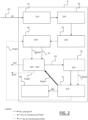
- Figures 1 to 4 are purely schematic illustrations of the installation and its lines, and of the process steps carried out there. These illustrations illustrate the sequence of process steps and the technologies used in the various steps. These illustrations are in no way limiting as to the arrangement of technologies in the installation and as to the technologies which constitute the installation.
- FIG. 1 shows a schematic illustration of the plant and method.
- the plant comprises a main flow line P, a first subdivision line Sub2, and a second subdivision line Sub3.
- the method comprises, after compressing the main flow, cooling the compressed main flow, comprising: the first subdivision S40 of the main flow into the main flow and a first cooling flow, the second subdivision S50 of the main flow into the main flow and a second cooling flow (subsequent cooling flow), the cooling S55-S555 of the first cooling flow by the second, and the cooling S60 of the main flow by the first cooling flow and the cooling S60' of the main flow by the at least one subsequent cooling flow.
- FIG. 2 shows a schematic illustration of the main line P of the plant and the process steps performed in the main line P.
- the main gas stream FP e.g. a natural gas, e.g. biomethane
- the process then comprises compressing S10 the main stream FP to 250 bar using a 4-stage HP (high pressure) compressor 10.
- the process may then comprise cooling S20 the main stream FP to 0°C using water-glycol, via any suitable water-glycol cooling device or system 20.
- the method may then comprise the pre-cooling S30 of the main flow FP to -40°C using a cooling unit 30.
- the method then comprises the first subdivision S40, using a valve 50, of the main flow FP into the main flow FP and the first cooling flow FSub2.
- the method also comprises the cooling S60 of the main flow FP by the first cooling flow FSub2 and S60' by the second cooling flow FSub3, and the cooling (S55, figure 3 ) of FSub2 by FSub3, then the second subdivision S50, using another valve 50, of the main flow FP into the main flow FP and the second cooling flow FSub3.
- the cooling S60 of the main flow is down to -157°C in an exchanger using the first cooling flow FSub2 which has itself been cooled using the second cooling flow FSub3.
- the method can then comprise an expansion S70 of the main flow FP to a saturation temperature of -150°C (equivalent to a pressure of 2.3 bar), in an expansion valve 70. It should be noted that the flow FSub2 does not mix with the Flow FP before the expansion, but after the cooling at the compressor suction after having exchanged with the glycolated water to recover its cold.
- the method may then comprise storing S80 the main stream FP in a bulk 80. A small amount of BOG may be generated during the last expansion S70 and/or due to thermal infiltration into the bulk 80.
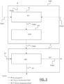
- the method comprises the cooling S55-S555 of the first cooling flow FSub2 by the second cooling flow FSub3.
- This may comprise, in a heat exchanger 55, a pre-cooling S55 of the first cooling flow FSub2 by the second cooling flow FSub3, then an expansion S555, in an expansion valve 555, of the pre-cooled first cooling flow FSub2.
- the heat exchanger 55 may be part of the at least one second subdivision line.
- the expansion may be at the pressure MP which is the pressure at the suction of the HP compressor, and which is between 2 and 8 bar depending on the application. This makes it possible to reduce the compression costs.
- the temperature of FSub2 is then between -128°C and -152°C.
- the S60 cooling of the compressed main stream (FP) can then include the use of the first cooling stream FSub2 in a heat exchanger.
- the cold energy of the cooled FSub2 is used to cool the main stream in the exchanger, assuming a pinch of 3°C.
- the stream leaving the exchanger is at a temperature of the order of -40°C. Therefore, at S65 the process can include the recovery of the remaining cold energy in a heat exchanger to partially cool the chilled water, then the recycling of the stream FSub2, which joins FSub3 and is recycled in the system.
- the method may comprise the expansion 55555 of the second cooling flow FSub3 in an expansion valve 5555.
- the method then comprises the use of the second cooling flow FSub3 in the heat exchanger 55 to cool the first cooling flow FSub2 (step S55). Taking into account a pinch of 3°C in the heat exchanger 55, the temperature of FSub3 becomes approximately -43°C.
- the method may then comprise a recycling step 5655 of the flow FSub3.
- the latter joins the BOG (“Boil-Off Gas”) when leaving the bulk 80, and the energy recovery is then carried out in a heat exchanger (not shown in the figures) with a glycolated water stream at ambient temperature.
- the BOG is at the storage tank.
- the temperature of the FSub3 stream increases before the FSub3 stream is compressed in low pressure (LP) compressors (not shown in the figures) up to the MP pressure so that it can be recycled into the system.
- LP low pressure
- the outgoing stream is then cooled to ambient temperature before being recycled into the system with the FSub2 stream.
- thermodynamic cycle used in the main flow line P may include the following technologies: instrumentation, heat exchangers, four-stage HP compressor with cooling, oil separator, buffer volume, electronic expansion valves, on-off (TOR) valve, bulk, and isolation valves.
- thermodynamic cycle used in the first line of subdivision Sub2 may include the following technologies: instrumentation, heat exchangers, electronic expansion valves, and isolation valves.
- thermodynamic cycle used in the second line of subdivision Sub3 can include the following technologies: instrumentation, heat exchangers, heat, electronic expansion valves, two-stage LP compressor with cooling and isolation valves.
- the installation may also include a subset of auxiliaries.
- This subset may include or consist of the following automated equipment: instrumentation, switches, (eg two) gas detectors for CH 4 , air heater for cooling refrigerants, pump for the glycol water network of the air heater, chilled water unit accompanied by a pump for cooling the entire process, cold unit for pre-cooling the main flow, and fan to extract air from the container.
- the process according to the examples described above with reference to the figures therefore consists in liquefying a gas (such as biomethane or any natural gas) to store it at a saturation temperature of -150 °C (2.3 bar).
- a gas such as biomethane or any natural gas
- the process is based on a modified Linde cycle, where the main gas flow is compressed to 250 bar, then pre-cooled using a cold refrigerant cycle to -40 °C.
- the main flow In the cryogenic section, the main flow is separated into two flows: the cooling flow which is expanded using a JT (Joule Thomson) valve and the main flow which is cooled in the heat exchanger. Two expansion and cooling steps make it possible to obtain a temperature below -150 °C for the main flow.
- the main flow is then expanded to reach the saturation temperature of -150 °C, then stored. A small amount of BOG can be generated and will be recycled into the system.
Landscapes
- Engineering & Computer Science (AREA)
- Physics & Mathematics (AREA)
- Mechanical Engineering (AREA)
- Thermal Sciences (AREA)
- General Engineering & Computer Science (AREA)
- Chemical & Material Sciences (AREA)
- Chemical Kinetics & Catalysis (AREA)
- General Chemical & Material Sciences (AREA)
- Oil, Petroleum & Natural Gas (AREA)
- Separation By Low-Temperature Treatments (AREA)
Abstract
Description
- La présente divulgation concerne le domaine technique des procédés et dispositifs pour la liquéfaction d'un gaz, comme du gaz naturel ou biométhane.
- Les installations de liquéfaction de gaz, comme le gaz naturel ou le biométhane, permettent de liquéfier un gaz pour le stocker de sorte que le transport du gaz ainsi liquéfié s'effectue à une pression de légèrement supérieure à la pression atmosphérique. Actuellement, plusieurs technologies et procédés existent pour la liquéfaction d'un gaz, notamment des processus de liquéfaction basé sur le cycle Linde. Le principe du cycle de Linde est de diviser le flux de gaz pour obtenir un flux secondaire destiné au refroidissement du flux principal, de sorte que le flux de gaz est subdivisé afin de s'autorefroidir.
- Dans ce contexte, il existe toutefois un besoin pour des solutions améliorées pour la liquéfaction de gaz.
- On propose pour cela un procédé de liquéfaction d'un gaz. Le procédé comprend la compression d'un flux principal du gaz. Le procédé comprend en outre le refroidissement du flux principal compressé. Le refroidissement du flux principal comprend une première subdivision du flux principal compressé. La première subdivision fournit un premier flux de refroidissement. Le refroidissement du flux principal comprend en outre au moins une subdivision ultérieure du flux principal compressé. La au moins une subdivision ultérieure du flux principal compressé fournissant au moins un flux de refroidissement ultérieur. Le refroidissement du flux principal comprend en outre le refroidissement du premier flux de refroidissement par le au moins un flux de refroidissement ultérieur. Le refroidissement du flux principal comprend en outre le refroidissement du flux principal compressé par le premier flux de refroidissement et le refroidissement du flux principal par le au moins un flux de refroidissement ultérieur.
- Comme discuté ultérieurement, le procédé fournit, en sortie (c'est-à-dire après exécution des étapes du procédé, dont les étapes de refroidissement) du gaz sous forme liquide, i.e. le gaz a été liquéfié.
- Le refroidissement du premier flux de refroidissement peut comprendre un pré-refroidissement du premier flux de refroidissement par le au moins un flux de refroidissement ultérieur. Le refroidissement du premier flux de refroidissement peut en outre comprendre une détente du premier flux de refroidissement pré-refroidi.
- Le refroidissement du flux principal compressé peut comprendre l'utilisation du premier flux de refroidissement détendu dans un échangeur de chaleur.
- Le procédé peut en outre comprendre, après la au moins une subdivision ultérieure et avant le pré-refroidissement du premier flux de refroidissement, la détente du au moins un flux de refroidissement ultérieur.
- Le pré-refroidissement du premier flux de refroidissement par le au moins un flux de refroidissement ultérieur peut comprendre l'utilisation du flux de refroidissement ultérieur détendu dans un échangeur de chaleur.
- Le procédé peut en outre comprendre le recyclage des flux de refroidissements détendus.
- Le procédé peut en outre comprendre, avant les subdivisions, un premier refroidissement du flux principal à l'aide d'eau-glycol, et un pré-refroidissement du flux principal à l'aide d'un groupe froid ou une source froide (par exemple à -45°C).
- Le procédé peut en outre comprendre, après le refroidissement du flux principal compressé par le premier flux de refroidissement, une détente du flux principal refroidi.
- Le procédé peut en outre comprendre le procédé, après la détente du flux principal refroidi, le stockage du flux principal refroidi et détendu dans un bulk.
- Le procédé peut être automatisé, c'est-à-dire implémenté via l'utilisation de toute technologie adaptée à l'automatisation d'un procédé de liquéfaction d'un gaz.
- On propose également une installation pour la liquéfaction d'un gaz selon le procédé. L'installation est donc un dispositif ou système adapté à la mise en oeuvre du procédé, pour la mise en oeuvre du procédé, et comprend notamment le matériel nécessaire à l'exécution du procédé. L'installation comprend :
- une ligne de flux principal destinée à la compression, aux subdivisions et au refroidissement du flux principal ;
- une première ligne de subdivision destinée au refroidissement du premier flux de refroidissement et au refroidissement du flux principal; et
- au moins une deuxième ligne de subdivision destinée au refroidissement du premier flux de refroidissement et du flux principal.
- un compresseur haute pression à 4 étages pour la compression du flux principal;
- un dispositif de refroidissement à l'aide d'eau glycol pour le premier refroidissement du flux principal à l'aide d'eau-glycol;
- un groupe froid pour le pré-refroidissement du flux principal à l'aide du groupe froid;
- une vanne de contrôle pour la première subdivision;
- au moins une autre vanne de contrôle pour la au moins une subdivision ultérieure;
- un échangeur de chaleur pour le refroidissement du flux principal par le premier flux de refroidissement;
- un détendeur pour la détente du flux principal refroidi; et
- un bulk pour le stockage du flux principal refroidi et détendu.
- La première ligne de subdivision peut comprendre :
- un échangeur de chaleur pour le pré-refroidissement du premier flux de refroidissement par le au moins un flux de refroidissement ultérieur; et
- un détendeur pour la détente du premier flux de refroidissement pré-refroidi.
- La au moins une deuxième ligne de subdivision peut comprendre:
- un détendeur pour la détente du au moins un flux de refroidissement ultérieur.
- un échangeur de chaleur pour le pré-refroidissement du premier flux de refroidissement par le au moins un flux de refroidissement ultérieur;
- L'installation peut être automatisée, i.e. peut comprendre toute technologie d'automatisation adaptée pour mettre en oeuvre le procédé de façon automatisée.
- Des exemples non-limitatifs vont maintenant être discutés en références au figures, où:
- Les
figures 1 à 4 montrent des illustrations schématiques d'exemples du procédé et de l'installation. - On propose un procédé de liquéfaction d'un gaz. Le procédé comprend la compression d'un flux principal du gaz. Le procédé comprend en outre le refroidissement du flux principal compressé. Le refroidissement du flux principal comprend une première subdivision du flux principal compressé. La première subdivision fournit un premier flux de refroidissement. Le refroidissement du flux principal comprend en outre au moins une subdivision ultérieure du flux principal compressé. la au moins une subdivision ultérieure du flux principal compressé fournissant au moins un flux de refroidissement ultérieur. Le refroidissement du flux principal comprend en outre le refroidissement du premier flux de refroidissement par le au moins un flux de refroidissement ultérieur. Le refroidissement du flux principal comprend en outre le refroidissement du flux principal compressé par le premier flux de refroidissement et le refroidissement du flux principal par le au moins un flux de refroidissement ultérieur.
- Cela constitut un procédé amélioré pour la liquéfaction d'un gaz.
- En effet, contrairement à un processus de refroidissement basé un cycle Linde classique, le procédé est basé sur un cycle Linde modifié dans lequel le flux principal est subdivisé une première fois, ce qui résulte en le flux principal et un premier flux de refroidissement, puis une deuxième fois (au moins), le au moins un flux de refroidissement ultérieur qui résulte de la au moins une subdivision ultérieure étant utilisé pour refroidir le premier flux de refroidissement, qui lui-même refroidit le flux principal. Le au moins au flux de refroidissement ultérieur refroidit également le flux principal. Cette pluralité de subdivision permet de réduire le débit nécessaire dans le flux de refroidissement de la première subdivision, comparé à un cycle Linde normal où cette subdivision serait la seule et où ce flux de refroidissement serait utilisé seul pour refroidir le flux principal. Cette réduction du débit du premier flux de refroidissement permet d'augmenter le débit du flux principal, ce qui améliore le rendement du procédé de liquéfaction ainsi que le rendement de l'installation.
- La au moins une subdivision ultérieure peut consister en un seule subdivision ultérieure, alors appelée « seconde subdivision ». Dans ce cas, le au moins un flux de refroidissement ultérieur consiste en un seul flux de refroidissement ultérieur, appelé « second flux de refroidissement », lequel est utilisé pour refroidir le premier flux de refroidissement. De manière alternative, la au moins une subdivision ultérieure peut consister en N subdivisions ultérieures respective chacune du flux principal en le flux principal et un flux de refroidissement ultérieur respectif, avec N un entier naturel strictement supérieur à 1. Dans ce cas, le flux de refroidissement ultérieur n-1 (i.e. qui correspond à la subdivision ultérieure n avec n un entier naturel appartement à [2 ;N]) est refroidit par le flux de refroidissement ultérieur n et refroidit lui-même le flux de refroidissement ultérieur n-2, le flux de refroidissement ultérieur 1 étant le premier flux de refroidissement et refroidissant le flux principal.
- On propose également une installation pour la liquéfaction d'un gaz selon le procédé. L'installation est donc un dispositif ou système adapté à la mise en oeuvre du procédé, pour la mise en oeuvre du procédé. L'installation comprend :
- une ligne de flux principal destinée à la compression, aux subdivisions et au refroidissement du flux principal;
- une première ligne de subdivision destinée au refroidissement du premier flux de refroidissement et au refroidissement du flux principal; et
- au moins une deuxième ligne de subdivision destinée au le refroidissement du premier flux de refroidissement.
- Dans le cas où il n'y a qu'une seule deuxième subdivision, i.e. la seconde subdivision, la au moins une deuxième ligne de subdivision consiste en une seule deuxième ligne de subdivision, appelée « seconde ligne de subdivision ».
- Le procédé et l'installation vont maintenant être décrits plus en détail en référence aux figures. Dans ce qui suit, la au moins une subdivision ultérieure peut consister en un seule subdivision ultérieure appelée « seconde subdivision », mais il doit être compris que la discussion qui suit se décline sans difficulté au cas de plusieurs subdivisions ultérieures. Il doit être compris que les
figures 1 à 4 sont des illustrations purement schématiques de l'installation et de ses lignes, et des étapes du procédé qui y sont exécutées. Ces illustrations permettent d'illustrer la succession des étapes du procédé et les technologies utilisées dans les diverses étapes. Ces illustrations ne sont en aucun cas limitatives quant à la disposition des technologies dans l'installation et quant aux technologies qui constituent l'installation. - Sauf indication contraire, toutes les températures données ci-dessous sont en degrés Celsius et toutes les pressions sont en bar et sont des pressions absolues. La notation « bar » dans la présente divulgation est donc équivalente à la notation « bar a » ou encore « bara » (désignant la pression absolue). Les valeurs numériques données dans la description ci-dessous des figures sont spécifiques au cas où le gaz est le méthane ou le biométhane. Pour d'autres gaz, les valeurs numériques doivent être convenablement adaptées. En particulier, toutes les valeurs présentées ci-dessous peuvent être adaptées selon les connaissances de l'homme du métier de sorte à ce que le gaz soit liquéfié à 100% en fonction de la pression de saturation du gaz.
- La
figure 1 montre une illustration schématique de l'installation et du procédé. L'installation comprend une ligne de flux principal P, une ligne de première subdivision Sub2, et une ligne de seconde subdivision Sub3. Comme illustré sur la figure, le procédé comprend, après la compression du flux principal, le refroidissement du flux principal compressé, comprenant : la première subdivision S40 du flux principal en le flux principal et un premier flux de refroidissement, la seconde subdivision S50 du flux principal en le flux principal et un second flux de refroidissement (flux de refroidissement ultérieur), le refroidissement S55-S555 du premier flux de refroidissement par le second, et le refroidissement S60 du flux principal par le premier flux de refroidissement et le refroidissement S60' du flux principal par le au moins un flux de refroidissement ultérieur. - La
figure 2 montre une illustration schématique de la ligne principale P de l'installation et des étapes du procédé réalisées dans la ligne principale P. Le flux principal de gaz FP (par exemple un gaz naturel, par exemple du biométhane), est alimenté (étape 50) à une pression constante comprise entre 2 et 8 bar. Le procédé comprend ensuite la compression S10 du flux principal FP jusqu'à 250 bar à l'aide d'un compresseur HP (haute pression) à 4 étages 10. Le procédé peut ensuite comprendre le refroidissement S20 du flux principal FP à 0°C à l'aide d'eau-glycol, via tout dispositif ou système 20 adapté de refroidissement à l'aide d'eau-glycol. Le procédé peut ensuite comprendre le pré-refroidissement S30 du flux principal FP à - 40°C à l'aide d'un groupe froid 30. Le procédé comprend ensuite la première subdivision S40, en utilisant une vanne 50, du flux principal FP en le flux principal FP et le premier flux de refroidissement FSub2. Le procédé comprend également le refroidissement S60 du flux principal FP par le premier flux de refroidissement FSub2 et S60' par le second flux de refroidissement FSub3, et le refroidissement (S55,figure 3 ) de FSub2 par FSub3, puis la seconde subdivision S50, en utilisant une autre vanne 50, du flux principal FP en le flux principal FP et le second flux de refroidissement FSub3. Le refroidissement S60 du flux principal est jusqu'à -157°C dans un échangeur en utilisant le premier flux de refroidissement FSub2 qui a lui-même été refroidi en utilisant le second flux de refroidissement FSub3. Le procédé peut ensuite comprendre une détente S70 du flux principal FP à une température de saturation - 150°C (équivalente à une pression de 2.3 bar), dans un détendeur 70. Il est à noter que le flux FSub2 ne se mélange pas avec le Flux FP avant la détente, mais après le refroidissement à l'aspiration du compresseur après avoir échangé avec l'eau glycolée pour récupérer son froid. Le procédé peut ensuite comprendre le stockage S80 du flux principal FP dans un bulk 80. Une petite quantité de BOG peut-être générée lors de la dernière détente S70 et/ou en raison d'infiltration thermique dans le bulk 80. - Pour l'exécution des étapes 50 à S80 décrites ci-dessus, la ligne de flux principal P de l'installation peut comprendre les dispositifs suivants :
- Des échangeurs de chaleur ;
- Un compresseur HP (haute pression) avec refroidissement ;
- Un compresseur BP (basse pression) pour recomprimer le gaz de FSub3 et passer de 1 bar à une pression entre 2 et 8 bar ;
- Un séparateur d'huile ;
- Un volume tampon ;
- Des détendeurs ;
- Une vanne tout ou rien (TOR) ;
- Un bulk; et
- Des vannes d'isolement.
- La
figure 3 montre une illustration schématique de la première ligne de subdivision Sub2 et de son utilisation pour l'exécution du procédé. Comme montré par la figure, le procédé comprend le refroidissement S55-S555 du premier flux de refroidissement FSub2 par le second flux de refroidissement FSub3. Cela peut comprendre, dans un échangeur de chaleur 55 un pré-refroidissement S55 du premier flux de refroidissement FSub2 par le second flux de refroidissement FSub3, puis une détente S555, dans un détendeur 555, du premier flux de refroidissement FSub2 pré-refroidi. De manière alternative, l'échangeur de chaleur 55 peut faire partie de la au moins une deuxième ligne de subdivision. La détente peut être à la pression MP qui est la pression à l'aspiration du compresseur HP, et qui se situe entre 2 et 8 bar selon l'application. Cela permet de diminuer les coûts de compression. La température de FSub2 se situe alors entre -128°C et -152°C. Le refroidissement S60 du flux principal (FP) compressé peut ensuite comprendre l'utilisation du premier flux de refroidissement FSub2 dans un changeur. En d'autres mots l'énergie froide de FSub2 refroidi est utilisée pour refroidir le flux principal dans l'échangeur, en considérant un pincement de 3°C. Le flux sortant de l'échangeur est à une température de l'ordre de -40°C. Par conséquent, à S65 le procédé peut comprendre la récupération de ce qui reste d'énergie froide dans un échangeur de chaleur pour refroidir partiellement l'eau glacée, puis le recyclage du flux FSub2, qui rejoint FSub3 et est recyclé dans le système. - Pour l'exécution des étapes décrites ci-dessus, la ligne de première subdivision Sub2 de l'installation peut comprendre le dispositifs suivants :
- Des échangeurs de chaleur ;
- Des détendeurs ; et
- Des vannes d'isolement.
- La
figure 4 montre une illustration schématique de la seconde ligne de subdivision Sub3, et de son utilisation pour l'exécution d'étapes du procédé. Suite à la subdivision S50, le procédé peut comprendre la détente 55555 du second flux de refroidissement FSub3 dans un détendeur 5555. La détente peut être à 1.1bar (température de saturation =-160°C), cette pression étant choisie de sorte à ce que le refroidissement du flux principal S60 soit d'environ -157°C dans l'échangeur de chaleur en tenant compte d'un pincement de 3°C. Le procédé comprend ensuite l'utilisation du second flux de refroidissement FSub3 dans l'échangeur de chaleur 55 pour refroidir le premier flux de refroidissement FSub2 (étape S55). Compte tenu d'un pincement de 3°C dans l'échangeur de chaleur 55, la température de FSub3 devient environ de -43°C. Le procédé peut ensuite comprendre une étape de recyclage 5655 du flux FSub3. Ce dernier rejoint le BOG (« Boil-Off Gaz ») en quittant le bulk 80, et la récupération d'énergie est alors effectuée dans un échangeur de chaleur (non représenté sur les figures) avec un flux d'eau glycolée à température ambiante. Le BOG est au niveau du réservoir de stockage. Ensuite, la température du flux FSub3 augmente avant que le flux FSub3 ne soit comprimé dans des compresseurs basse pression (LP) (non-représentés sur les figures) jusqu'à la pression MP afin qu'il puisse être recyclé dans le système. Le flux sortant est ensuite refroidit à la température ambiante avant d'être recyclé dans le système avec le flux FSub2. - Le cycle thermodynamique utilisé dans la ligne de flux principal P peut comprendre les technologies suivantes : instrumentation, échangeurs de chaleur, compresseur HP à quatre étages avec refroidissement, séparateur d'huile, volume tampon, détendeurs électroniques, vanne tout ou rien (TOR), bulk, et vannes d'isolement.
- Le cycle thermodynamique utilisé dans la première ligne de subdivision Sub2 peut comprendre les technologies suivantes : instrumentation, échangeurs de chaleur, détendeurs électroniques, et vannes d'isolement.
- Le cycle thermodynamique utilisé dans la seconde ligne de subdivision Sub3 peut comprendre les technologies suivantes : instrumentation, échangeurs de chaleur, détendeurs électroniques, compresseur LP à deux étages avec refroidissement et vannes d'isolement.
- L'installation peut également comprendre un sous-ensemble d'auxiliaires. Ce sous ensemble peut comprendre ou être constitué des équipements automatisés suivants : instrumentation, switches, (e.g. deux) détecteurs de gaz pour CH4, aérotherme pour le refroidissement des fluides frigorigènes, pompe pour le réseau d'eau glycolée de l'aérotherme, groupe d'eau glacée accompagnée d'une pompe pour le refroidissement de l'ensemble du process, groupe froid pour le pré-refroidissement du flux principal, et ventilateur pour extraire l'air du container.
- Le procédé selon les exemples décrits ci-dessus en référence aux figures consistent donc à liquéfier un gaz (comme le biométhane ou tout gaz naturel) pour le stocker à une température de saturation de -150 °C (2,3 bar). Le processus est basé sur un cycle Linde modifié, où le flux principal de gaz est comprimé jusqu'à 250 bar, puis pré-refroidi à l'aide d'un cycle frigorigène froid jusqu'à -40 °C. Dans la section cryogénique, le flux principal est séparé en deux flux : le flux de refroidissement qui est détendu à l'aide d'une vanne JT (Joule Thomson) et le flux principal qui est refroidi dans l'échangeur de chaleur. Deux étapes de détente et de refroidissement permettent d'obtenir une température inférieure à -150 °C pour le flux principal. Le flux principal est ensuite détendu pour atteindre la température de saturation de - 150 °C, puis stocké. Une petite quantité de BOG peut être générée et sera recyclée dans le système.
- Les exemples de l'installation et du procédé décrits ci-dessus en référence aux figures réalisent les objectifs suivants :
- Objectifs pour la compression HP et la liquéfaction du flux principal :
- ∘ Comprimer le flux principal à l'aide d'un compresseur HP allant jusqu'à 250 bar ;
- ∘ Pré-refroidir le flux principal à -40°C ;
- ∘ Liquéfaction : refroidir le flux principal en répartissant le flux en deux subdivisions pour subir ensuite une détente et être stocké à -150°C ;
- Objectifs du sous-ensemble Sub2 :
- ∘ Contrôler le débit dans la ligne Sub2 et la détente du débit à BP1=MP;
- ∘ Première étape de refroidissement du flux principal ;
- ∘ Recyclage du flux dans le système ;
- Objectifs du sous-ensemble Sub3 :
- ∘ Contrôler le débit dans la ligne Sub3 et détente du débit à BP2=1.1 bar ;
- ∘ Deuxième refroidissement du flux principal ;
- ∘ Pré-refroidissement du flux Sub2 ;
- ∘ Compression LP (basse pression) du flux à BP1 .
Claims (15)
- Procédé de liquéfaction d'un gaz, comprenant :- la compression (S10) d'un flux principal (FP) du gaz ;- le refroidissement du flux principal compressé, le refroidissement du flux principal (FP) comprenant :∘ une première subdivision (S40) du flux principal (FP) compressé, la première subdivision fournissant un premier flux de refroidissement (FSub2) ;∘ au moins une subdivision ultérieure (S50) du flux principal (FP) compressé, la au moins une subdivision ultérieure du flux principal (FP) compressé fournissant au moins un flux de refroidissement ultérieur (FSub3),∘ le refroidissement (S55-S555) du premier flux de refroidissement (FSub2) par le au moins un flux de refroidissement ultérieur (FSub3), et∘ le refroidissement (S60) du flux principal (FP) compressé par le premier flux de refroidissement (FSub2) et le refroidissement (S60') du flux principal par le au moins un flux de refroidissement ultérieur (FSub3).
- Procédé selon la revendication 1, dans lequel le refroidissement du premier flux de refroidissement (FSub2) comprend :- un pré-refroidissement (S55) du premier flux de refroidissement (FSub2) par le au moins un flux de refroidissement ultérieur (FSub3) ; et- une détente (S555) du premier flux de refroidissement (FSub2) pré-refroidi.
- Procédé selon la revendication 2, dans lequel le refroidissement (S60) du flux principal (FP) compressé comprend :- l'utilisation du premier flux de refroidissement (FSub2) détendu dans un échangeur de chaleur.
- Procédé selon la revendication 2 ou 3, dans lequel le procédé comprend en outre, après la au moins une subdivision ultérieure (S50) et avant le pré-refroidissement (S55) du premier flux de refroidissement (FSub2) :- la détente (S5555) du au moins un flux de refroidissement ultérieur (FSub3).
- Procédé selon la revendication 4, dans lequel le pré-refroidissement (S55) du premier flux de refroidissement (FSub2) par le au moins un flux de refroidissement ultérieur (FSub3) comprend :- l'utilisation du flux de refroidissement ultérieur (FSub3) détendu dans un échangeur de chaleur (55).
- Procédé selon la revendication 5, dans lequel le procédé comprend en outre le recyclage (S65-S655) des flux de refroidissements détendus.
- Procédé selon l'une quelconque des revendications 1 à 6, dans lequel le procédé comprend en outre, avant les subdivisions (S40-S50) :- un premier refroidissement (S20) du flux principal (FP) à l'aide d'eau-glycol ; et- un pré-refroidissement (S30) du flux principal (FP) à l'aide d'un groupe froid ou d'une source froide (30).
- Procédé selon l'une quelconque des revendications 1 à 7, dans lequel le procédé comprend en outre, après le refroidissement (S60) du flux principal (FP) compressé par le premier flux de refroidissement (FSub2) :- une détente (S70) du flux principal (FP) refroidi.
- Procédé selon la revendication 8, dans lequel le procédé comprend un outre, après la détente (S70) du flux principal (FP) refroidi :- le stockage (S80) du flux principal (FP) refroidi et détendu dans un bulk (80).
- Procédé selon l'une quelconque des revendications 1 à 9, dans lequel le procédé est automatisé.
- Une installation pour la liquéfaction d'un gaz selon le procédé d'une quelconque des revendications 1 à 10, dans lequel l'installation comprend :- une ligne de flux principal (P) destinée à la compression, aux subdivisions et au refroidissement du flux principal (FP) ;- une première ligne de subdivision (Sub2) destinée au refroidissement du premier flux de refroidissement (FSub2) et au refroidissement du flux principal (FP) ; et- au moins une deuxième ligne de subdivision (Sub3) destinée au refroidissement du premier flux de refroidissement (FSub2) et du flux principal (FP).
- Installation selon la revendication 11, dans laquelle la ligne de flux principal (P) comprend :- un compresseur haute pression à 4 étages (10) pour la compression (S10) du flux principal (FP) ;- un dispositif (20) de refroidissement à l'aide d'eau glycol pour le premier refroidissement (S20) du flux principal (FP) à l'aide d'eau-glycol ;- un groupe froid (30) pour le pré-refroidissement (S30) du flux principal (FP) à l'aide du groupe froid (30) ;- une vanne de contrôle (40) pour la première subdivision (S40) ;- au moins une autre vanne de contrôle (50) pour la au moins une subdivision ultérieure (S50) ;- un échangeur de chaleur pour le refroidissement (S60) du flux principal (FP) par au moins un flux de refroidissement ultérieur (FSub3) et un échangeur de chaleur pour le refroidissement S60 du flux principal (FP) par le premier flux de refroidissement (FSub2) ;- un détendeur (70) pour la détente (S70) du flux principal refroidi ; et- un bulk (80) pour le stockage (S80) du flux principal refroidi et détendu.
- Installation selon la revendication 11 ou 12, dans laquelle la première ligne de subdivision (Sub2) comprend :- un échangeur de chaleur (55) pour le pré-refroidissement (S55) du premier flux de refroidissement (FSub2) par le au moins un flux de refroidissement ultérieur (FSub3) ;et- un détendeur (555) pour la détente (S555) du premier flux de refroidissement (FSub2) pré-refroidi.
- Installation selon la revendication 11 ou 12 ou 13, dans laquelle la au moins une deuxième ligne de subdivision (Sub3) comprend :- un détendeur 5555 pour la détente (S5555) du au moins un flux de refroidissement ultérieur (FSub3) ;- un échangeur de chaleur (55) pour le pré-refroidissement (S55) du premier flux de refroidissement (FSub2) par le au moins un flux de refroidissement ultérieur (FSub3).
- Installation selon l'une quelconque des revendications 11 à 14, dans laquelle l'installation est automatisée.
Priority Applications (6)
| Application Number | Priority Date | Filing Date | Title |
|---|---|---|---|
| EP23169218.7A EP4450909A1 (fr) | 2023-04-21 | 2023-04-21 | Procédé de liquéfaction d'un gaz |
| JP2025561428A JP2026512543A (ja) | 2023-04-21 | 2024-03-29 | ガスの液化方法 |
| MX2025012505A MX2025012505A (es) | 2023-04-21 | 2024-03-29 | Metodo para licuar un gas |
| PCT/EP2024/058742 WO2024217853A1 (fr) | 2023-04-21 | 2024-03-29 | Procede de liquefaction d'un gaz |
| KR1020257039185A KR20260005329A (ko) | 2023-04-21 | 2024-03-29 | 가스 액화 방법 |
| CN202480026839.4A CN121713035A (zh) | 2023-04-21 | 2024-03-29 | 用于液化气体的方法 |
Applications Claiming Priority (1)
| Application Number | Priority Date | Filing Date | Title |
|---|---|---|---|
| EP23169218.7A EP4450909A1 (fr) | 2023-04-21 | 2023-04-21 | Procédé de liquéfaction d'un gaz |
Publications (1)
| Publication Number | Publication Date |
|---|---|
| EP4450909A1 true EP4450909A1 (fr) | 2024-10-23 |
Family
ID=86142795
Family Applications (1)
| Application Number | Title | Priority Date | Filing Date |
|---|---|---|---|
| EP23169218.7A Pending EP4450909A1 (fr) | 2023-04-21 | 2023-04-21 | Procédé de liquéfaction d'un gaz |
Country Status (6)
| Country | Link |
|---|---|
| EP (1) | EP4450909A1 (fr) |
| JP (1) | JP2026512543A (fr) |
| KR (1) | KR20260005329A (fr) |
| CN (1) | CN121713035A (fr) |
| MX (1) | MX2025012505A (fr) |
| WO (1) | WO2024217853A1 (fr) |
Citations (4)
| Publication number | Priority date | Publication date | Assignee | Title |
|---|---|---|---|---|
| US3702063A (en) * | 1968-11-04 | 1972-11-07 | Linde Ag | Refrigeration cycle for the aliquefaction of natural gas |
| EP3045849A2 (fr) * | 2015-01-14 | 2016-07-20 | Luciano Ghergo | Installation de liquéfaction de gaz méthane |
| WO2019145230A1 (fr) * | 2018-01-29 | 2019-08-01 | Innogy Se | Génération de gaz liquéfié dans un accumulateur de gaz |
| US10788259B1 (en) * | 2015-12-04 | 2020-09-29 | Chester Lng, Llc | Modular, mobile and scalable LNG plant |
-
2023
- 2023-04-21 EP EP23169218.7A patent/EP4450909A1/fr active Pending
-
2024
- 2024-03-29 CN CN202480026839.4A patent/CN121713035A/zh active Pending
- 2024-03-29 WO PCT/EP2024/058742 patent/WO2024217853A1/fr not_active Ceased
- 2024-03-29 JP JP2025561428A patent/JP2026512543A/ja active Pending
- 2024-03-29 KR KR1020257039185A patent/KR20260005329A/ko active Pending
- 2024-03-29 MX MX2025012505A patent/MX2025012505A/es unknown
Patent Citations (4)
| Publication number | Priority date | Publication date | Assignee | Title |
|---|---|---|---|---|
| US3702063A (en) * | 1968-11-04 | 1972-11-07 | Linde Ag | Refrigeration cycle for the aliquefaction of natural gas |
| EP3045849A2 (fr) * | 2015-01-14 | 2016-07-20 | Luciano Ghergo | Installation de liquéfaction de gaz méthane |
| US10788259B1 (en) * | 2015-12-04 | 2020-09-29 | Chester Lng, Llc | Modular, mobile and scalable LNG plant |
| WO2019145230A1 (fr) * | 2018-01-29 | 2019-08-01 | Innogy Se | Génération de gaz liquéfié dans un accumulateur de gaz |
Also Published As
| Publication number | Publication date |
|---|---|
| JP2026512543A (ja) | 2026-04-16 |
| WO2024217853A1 (fr) | 2024-10-24 |
| KR20260005329A (ko) | 2026-01-09 |
| CN121713035A (zh) | 2026-03-20 |
| MX2025012505A (es) | 2026-02-03 |
Similar Documents
| Publication | Publication Date | Title |
|---|---|---|
| JP6718498B2 (ja) | エンジンを備えた船舶 | |
| RU2645185C1 (ru) | Способ сжижения природного газа по циклу высокого давления с предохлаждением этаном и переохлаждением азотом "арктический каскад" и установка для его осуществления | |
| US20180320957A1 (en) | Low-temperature mixed--refrigerant for hydrogen precooling in large scale | |
| KR101593970B1 (ko) | 증발가스의 다단 재액화 시스템 및 방법 | |
| US11927391B2 (en) | Liquefaction of production gas | |
| KR20160142257A (ko) | 선박 | |
| JP6837049B2 (ja) | エンジンを備えた船舶 | |
| KR101831177B1 (ko) | 엔진을 포함하는 선박 | |
| JP2010507771A (ja) | 炭化水素流を液化する方法及び装置 | |
| KR101854977B1 (ko) | 선박용 액화천연가스의 증발가스 부분재액화장치 | |
| WO2024217853A1 (fr) | Procede de liquefaction d'un gaz | |
| US20180142949A1 (en) | Partial open-loop nitrogen refrigeration process and system for an oil or gas production operation | |
| KR102705009B1 (ko) | 선박의 증발가스 재액화 시스템 및 방법 | |
| KR101767551B1 (ko) | 선박의 증발가스 재액화 장치 | |
| KR101895788B1 (ko) | 선박 | |
| RU2740112C1 (ru) | Способ сжижения природного газа "Полярная звезда" и установка для его осуществления | |
| KR102276362B1 (ko) | 증발가스 재액화 시스템 및 방법 | |
| KR101686513B1 (ko) | 증발가스 재액화 장치 및 방법 | |
| US20250334330A1 (en) | Gas liquefaction system with multiple refrigerant cycles | |
| KR20170000180A (ko) | 증발가스 재액화 시스템 | |
| KR101775048B1 (ko) | 엔진을 포함하는 선박 | |
| FR3068770A1 (fr) | Dispositif et procede de liquefaction d’un gaz naturel ou d’un biogaz | |
| KR20240137980A (ko) | 이산화탄소 처리 시스템 및 이를 포함하는 구조물 | |
| WO2017039271A1 (fr) | Procédé de reliquéfaction de gaz d'évaporation | |
| JP2025505735A (ja) | ボイルオフガスの再液化及びlngタンクへリサイクルするための方法及び装置 |
Legal Events
| Date | Code | Title | Description |
|---|---|---|---|
| PUAI | Public reference made under article 153(3) epc to a published international application that has entered the european phase |
Free format text: ORIGINAL CODE: 0009012 |
|
| STAA | Information on the status of an ep patent application or granted ep patent |
Free format text: STATUS: THE APPLICATION HAS BEEN PUBLISHED |
|
| AK | Designated contracting states |
Kind code of ref document: A1 Designated state(s): AL AT BE BG CH CY CZ DE DK EE ES FI FR GB GR HR HU IE IS IT LI LT LU LV MC ME MK MT NL NO PL PT RO RS SE SI SK SM TR |
|
| STAA | Information on the status of an ep patent application or granted ep patent |
Free format text: STATUS: REQUEST FOR EXAMINATION WAS MADE |
|
| 17P | Request for examination filed |
Effective date: 20250423 |
|
| STAA | Information on the status of an ep patent application or granted ep patent |
Free format text: STATUS: EXAMINATION IS IN PROGRESS |
|
| 17Q | First examination report despatched |
Effective date: 20250929 |
|
| P01 | Opt-out of the competence of the unified patent court (upc) registered |
Free format text: CASE NUMBER: UPC_APP_0004129_4450909/2026 Effective date: 20260204 |