EP4450937A1 - Thermomètre alimentaire, système et procédé - Google Patents
Thermomètre alimentaire, système et procédé Download PDFInfo
- Publication number
- EP4450937A1 EP4450937A1 EP24170393.3A EP24170393A EP4450937A1 EP 4450937 A1 EP4450937 A1 EP 4450937A1 EP 24170393 A EP24170393 A EP 24170393A EP 4450937 A1 EP4450937 A1 EP 4450937A1
- Authority
- EP
- European Patent Office
- Prior art keywords
- housing
- thermometer
- battery
- housing part
- food
- Prior art date
- Legal status (The legal status is an assumption and is not a legal conclusion. Google has not performed a legal analysis and makes no representation as to the accuracy of the status listed.)
- Pending
Links
Images


Classifications
-
- G—PHYSICS
- G01—MEASURING; TESTING
- G01K—MEASURING TEMPERATURE; MEASURING QUANTITY OF HEAT; THERMALLY-SENSITIVE ELEMENTS NOT OTHERWISE PROVIDED FOR
- G01K13/00—Thermometers specially adapted for specific purposes
-
- G—PHYSICS
- G01—MEASURING; TESTING
- G01K—MEASURING TEMPERATURE; MEASURING QUANTITY OF HEAT; THERMALLY-SENSITIVE ELEMENTS NOT OTHERWISE PROVIDED FOR
- G01K1/00—Details of thermometers not specially adapted for particular types of thermometer
- G01K1/08—Protective devices, e.g. casings
-
- G—PHYSICS
- G01—MEASURING; TESTING
- G01K—MEASURING TEMPERATURE; MEASURING QUANTITY OF HEAT; THERMALLY-SENSITIVE ELEMENTS NOT OTHERWISE PROVIDED FOR
- G01K1/00—Details of thermometers not specially adapted for particular types of thermometer
- G01K1/08—Protective devices, e.g. casings
- G01K1/12—Protective devices, e.g. casings for preventing damage due to heat overloading
-
- G—PHYSICS
- G01—MEASURING; TESTING
- G01K—MEASURING TEMPERATURE; MEASURING QUANTITY OF HEAT; THERMALLY-SENSITIVE ELEMENTS NOT OTHERWISE PROVIDED FOR
- G01K1/00—Details of thermometers not specially adapted for particular types of thermometer
- G01K1/14—Supports; Fastening devices; Arrangements for mounting thermometers in particular locations
-
- G—PHYSICS
- G01—MEASURING; TESTING
- G01K—MEASURING TEMPERATURE; MEASURING QUANTITY OF HEAT; THERMALLY-SENSITIVE ELEMENTS NOT OTHERWISE PROVIDED FOR
- G01K1/00—Details of thermometers not specially adapted for particular types of thermometer
- G01K1/16—Special arrangements for conducting heat from the object to the sensitive element
-
- G—PHYSICS
- G01—MEASURING; TESTING
- G01K—MEASURING TEMPERATURE; MEASURING QUANTITY OF HEAT; THERMALLY-SENSITIVE ELEMENTS NOT OTHERWISE PROVIDED FOR
- G01K7/00—Measuring temperature based on the use of electric or magnetic elements directly sensitive to heat ; Power supply therefor, e.g. using thermoelectric elements
- G01K7/16—Measuring temperature based on the use of electric or magnetic elements directly sensitive to heat ; Power supply therefor, e.g. using thermoelectric elements using resistive elements
-
- G—PHYSICS
- G01—MEASURING; TESTING
- G01K—MEASURING TEMPERATURE; MEASURING QUANTITY OF HEAT; THERMALLY-SENSITIVE ELEMENTS NOT OTHERWISE PROVIDED FOR
- G01K2207/00—Application of thermometers in household appliances
- G01K2207/02—Application of thermometers in household appliances for measuring food temperature
- G01K2207/06—Application of thermometers in household appliances for measuring food temperature for preparation purposes
-
- G—PHYSICS
- G01—MEASURING; TESTING
- G01K—MEASURING TEMPERATURE; MEASURING QUANTITY OF HEAT; THERMALLY-SENSITIVE ELEMENTS NOT OTHERWISE PROVIDED FOR
- G01K2215/00—Details concerning sensor power supply
Definitions
- the invention relates to a food thermometer, a system with a food thermometer and a tool and a method for inserting a battery into a food thermometer
- thermometer also referred to as a "thermometer” in this document
- the thermometer can be designed and suitable for being inserted into a dish in order to measure the temperature inside the dish.
- Such a thermometer then typically has a tip so that it can be inserted into meat, for example.
- a temperature-sensitive sensor of the thermometer can then be located in or near the tip in order to be able to measure the internal temperature of the meat. Examples of such thermometers can be found in the publications EP 0687866A1 , US 6,568,848 B1 and US 7,075,442 B2 known.
- a food thermometer can measure temperatures that can occur when preparing a meal. Temperatures that deviate significantly from this cannot be measured.
- a thermometer can also withstand the ambient conditions that can occur when preparing a meal. The thermometer is basically designed so that it can be used in a conventional oven, i.e. at temperatures of up to 250°C, up to 300°C or up to 350°C. Higher temperatures cannot be measured.
- a food thermometer in the sense of the present invention can also withstand a steam atmosphere. A food thermometer is therefore basically encapsulated in a watertight manner.
- a food thermometer in the sense of the present invention is resistant to common ingredients in a meal, such as acid from lemons or vinegar.
- a food thermometer typically has an electrically and/or electronically operated temperature measuring unit for measuring the temperature and a battery for operating the temperature measuring unit.
- the battery is usually rechargeable, so that a certain lifespan of the thermometer can be guaranteed. However, the lifespan is limited because the rechargeable battery is subject to aging, so that its capacity continuously decreases with age. If the capacity is no longer sufficient for certain food preparation processes, the thermometer must be replaced.
- thermometer according to claim 1 and a system and a method according to the independent claims are used.
- Advantageous embodiments are specified in the subclaims.
- a food thermometer is used to solve the problem.
- the food thermometer comprises a temperature measuring unit and a battery holder for holding a battery to operate the temperature measuring unit.
- the temperature measuring unit and the battery holder are housed in a housing.
- the housing has a lockable opening to release the battery holder for changing the battery.
- thermometer The opening allows the battery to be changed.
- a battery can be removed from the battery holder and a new battery can be inserted into the battery holder.
- the service life of the thermometer according to the invention can be significantly extended by the option of changing the battery. Repairs are made easier. In this way, resources can be saved, emissions avoided and sustainability improved.
- the thermometer can include the battery.
- the battery is suitable for operating the temperature measuring unit.
- the battery is a rechargeable battery.
- the opening is used to release the battery holder.
- the opening can be opened for this purpose.
- the opening is used to open the housing.
- the opening provides access through the housing to the inside of the thermometer and to the battery holder. Releasing the battery holder means opening it in such a way that a battery can be removed from the battery holder and/or inserted into the battery holder.
- the closable opening can also be referred to as an interface or mounting interface.
- the opening can basically be located at any point on the thermometer that allows the battery to be changed.
- the opening can be closed.
- the closure can be achieved, for example, with one or more closure elements.
- a closure element can be part of the housing or an additional closure element such as a cover, a flap or a flexible tab.
- Such a closure element can be attached to the housing, for example in a movable manner such as pivoting, or can be separate from the housing.
- the thermometer comprises the housing.
- the housing When closed, the housing is preferably closed in such a way that the ingress of liquid and/or steam is prevented, so that the thermometer can also be operated in a hot atmosphere, e.g. in an oven, and the interior of the thermometer is protected accordingly.
- the opening can therefore typically be closed in such a way that the functionality of the thermometer is fully and permanently maintained. Accordingly, the tightness, in particular against liquid and steam, as well as the high temperature resistance are maintained.
- the opening and closing of the housing using the lockable opening is non-destructive and reversible. This means that after closing, the condition before opening can typically be restored. This can be repeated as often as desired, apart from normal wear and tear.
- a battery holder is a cavity that is suitable for holding a battery.
- the battery holder also holds the battery in place.
- the battery can be placed in the cavity and used in this position to operate the temperature measuring unit.
- the food thermometer has typically has two electrical contacts for the battery. These can be arranged in such a way that electrical contact can be made between the two poles of the battery when the battery is in the battery holder.
- the temperature measuring unit is an electrically and/or electronically operated unit for measuring a temperature.
- the temperature measuring unit comprises a temperature sensor for measuring a temperature.
- a temperature sensor is an electrical or electronic component that delivers an electrical signal as a measure of the temperature.
- the temperature sensor can, for example, comprise an electrical conductor whose temperature-dependent electrical resistance is measured. The measured electrical resistance is then the measure of the temperature.
- the temperature measuring unit comprises evaluation electronics.
- the evaluation electronics can determine temperature values from electrical signals from a temperature sensor.
- the evaluation electronics can be adjacent to the battery holder. This arrangement allows a particularly space-saving design.
- the evaluation electronics can comprise an integrated circuit or be formed by such a circuit.
- the food thermometer comprises a radio unit for wirelessly transmitting and/or receiving signals, in particular data and/or commands.
- the radio unit can be operated by means of the battery and/or be part of the temperature measuring unit.
- the thermometer preferably comprises an antenna for wirelessly transmitting and/or receiving information in the rear part opposite the tip.
- the antenna can be part of the radio unit. For example, temperatures measured in this way can be sent to an external device such as a smartphone or a food processor.
- commands such as a command to carry out a measurement with an external device can be sent to the thermometer and received by the thermometer.
- the thermometer comprises a tip for piercing a food or a dish.
- the thermometer comprises a handle.
- a handle is designed and suitable to be gripped in order to pierce the tip into a food and to pull it out of the food or the dish made from it.
- a The handle part can therefore comprise a cover or casing made of a thermally insulating material such as plastic.
- the antenna can be arranged in the handle part.
- the food thermometer is no longer than 30 cm, preferably no longer than 20 cm. In one embodiment, the food thermometer is longer than 10 cm, preferably longer than 12 cm.
- the housing has a first housing part and a second housing part.
- the second housing part can be separated from the first housing part.
- the opening can be opened.
- the second housing part can in particular be reconnected to the first housing part.
- there are two openings. Each of the openings is opened by separating the two housing parts and/or closed by connecting the two housing parts. In other words, each housing part serves to close the other housing part.
- the battery holder is arranged at least predominantly and in one embodiment completely in one of the two housing parts.
- the opening in the sense of claim 1 is the opening of this housing part with the battery holder.
- the first housing part and the second housing part are located at different positions along the longitudinal direction of the food thermometer.
- the first housing part faces the tip of the thermometer and the second housing part corresponds to a rear part of the thermometer.
- the housing is divided into two parts along its longitudinal direction. A dividing line or dividing plane between the housing parts can run essentially perpendicular to the longitudinal direction. In this way, a closable opening can be provided with particularly little technical effort.
- the food thermometer has a tip for piercing a food.
- the second housing part comprises the tip and/or has a length of at most 6 cm, in particular of at most 4 cm. The length is in particular at least 1 cm. The length is measured along the longitudinal extent of the food thermometer.
- the battery is located in the area of the tip. This is particularly advantageous since, when used in a hot atmosphere, for example in an oven, the tip is inserted into the food being prepared. Since the inside of the food is the last to heat up, this is typically the coolest place. Thus, the battery is protected from excessive heat, which significantly increases its service life.
- the part of the battery furthest from the tip measured along the length of the thermometer, is no more than 8 cm, preferably no more than 6 cm, and most preferably no more than 5 cm from the tip.
- the short length of the second housing part means that the housing can and must be opened in the area of the tip. This means that access to the position of the battery in the tip is possible without the battery having to be moved a long distance inside the thermometer to be changed. This makes it particularly easy to change the battery. It is not necessary to pull out an internal part of the thermometer, such as a circuit board or the like. This prevents damage to this internal part. It is also prevented that the internal part and/or the battery become jammed when moving through the housing.
- thermometer Since the tip of the thermometer is used to pierce food, it must be sealed particularly tightly.
- the thermometer is designed so that when the opening is closed, the outer contour of the housing is essentially smooth, at least in the area of the opening. This prevents food residue or other dirt from accumulating. It also ensures that the thermometer can be easily inserted into and removed from food.
- the food thermometer has a connecting means for positively connecting the first housing part and the second housing part to one another in the connected state.
- the connecting means can serve as a closure for closing the opening.
- the connecting means can be one-piece or multi-piece.
- the connecting means can, for example, comprise a first thread in the first housing part and a corresponding second thread in the second housing part.
- a form-fitting connection is then present at least in the axial and radial directions, in relation to the central longitudinal axis of the thermometer. In this way, a permanent and reversible opening and closing of the opening can be ensured particularly easily.
- the thread is preferably a fine thread, i.e. has a narrower thread profile and a lower pitch. This enables greater strength through greater self-locking.
- the connecting means can comprise a screw, for example a grub screw, and one or two holes.
- the screw can contact the other of the two housing parts through a through hole in one of the two housing parts or be screwed into a hole, for example a threaded hole, in the other housing part, thus enabling a positive connection.
- the screw can be present as a single part or can be held captively in one of the housing parts.
- the food thermometer it is also possible in principle for the food thermometer to have a connecting means to connect the first housing part and the second housing part to one another in a force-locking manner when connected.
- the connection can be achieved, for example, with a press fit or by clamping.
- a form-fitting connection allows for greater strength and tightness and is therefore preferable.
- the food thermometer is designed in such a way that the battery holder can be accessed immediately after the housing is opened.
- the cavity of the battery holder is therefore located so close to the opening that it is directly accessible after the housing is opened. This means that the battery can be removed or inserted immediately and therefore particularly easily after opening.
- a positioning element may be present for positioning the battery in order to move the battery into or out of the battery holder and/or to hold the battery in position in the battery holder.
- the battery can be inserted into or removed from the battery holder together with such a positioning element.
- the food thermometer comprises a sealing element which seals the housing when closed, e.g. after the opening is closed. Sealing means sealing against water, steam and/or other contaminants. In particular, the opening is sealed. This ensures that the inside of the thermometer is protected from the atmosphere surrounding the thermometer. The entry of substances into the inside of the thermometer through the opening is thus prevented. For example, a dishwasher-safe design of the thermometer is possible.
- the sealing element is arranged in such a way that it contacts both the first housing part or an element directly or indirectly attached to the first housing part and the second housing part or an element directly or indirectly attached to the second housing part in order to seal these two parts against each other.
- the sealing element is designed and arranged such that at least one region of the sealing element is pressed into a sealing position when the first housing part is connected to the second housing part by means of the connecting means.
- the connecting means causes the sealing element to be pressed into a sealing position.
- a connecting means such as a grub screw can press directly or indirectly on the sealing element, or a combination of corresponding threads in each of the housing parts can be arranged such that a seal is compressed, pivoted and/or deflected when screwed together.
- Pressing into a sealing position means that at least part of the sealing element is moved by a counterpart against which it is to be sealed. In this way, a particularly tight seal is achieved.
- part of the sealing element is rotated, folded or otherwise deformed in order to lie flatly or linearly against the counterpart.
- the sealing element is compressed by the pressure of the counterpart, whereby at least one side of the sealing element is deformed. In this way, a particularly secure seal can be achieved.
- This design of the sealing element is also referred to as a self-reinforcing seal.
- one or more pre-tensioning elements are provided which are pre-tensioned when the two housing parts are pressed together.
- a force must be applied which is greater than the pre-tensioning force of the one or more pre-tensioning elements.
- Springs, rubber elements such as rubber sleeves and/or membrane elements can be used as pre-tensioning elements. In this way, a particularly high level of tightness is achieved.
- the user receives feedback on the existing sealing effect during assembly through the pre-tensioning force.
- the pressing together can take place, for example, when screwing the two housing parts together.
- the food thermometer comprises a sealing element which seals the first housing part or the second housing part when the housing is open.
- the housing part in which the battery holder is not located is sealed.
- This can be the housing part in which at least part of the temperature measuring unit, a control unit and/or a radio unit of the thermometer is located. In this way, these parts of the thermometer can be protected from contamination even when the thermometer is open.
- a sealing element which seals the housing after the opening is closed and which seals the first housing part or the second housing part when the housing is open. Both sealing functions are therefore fulfilled by a single sealing element.
- the sealing functions can be implemented by different areas of the sealing element. Both sealing functions can thus be implemented in a particularly simple technical manner.
- thermometer is designed so that the housing can be opened manually without the need for tools.
- the thermometer comprises a spring contact for electrically contacting the battery.
- a spring element is provided for electrical contacting, which exerts a spring force on the electrical contact of the battery. In this way, it can be ensured that the electrical contact is made reliably even if the opening is opened and closed several times.
- the housing is electrically conductive and/or metallic.
- the thermometer is designed such that the housing is or can be electrically connected to a contact of the battery. In other words, the housing serves to close the circuit. This is technically particularly simple, since only one cable is required inside the thermometer. In addition, the available internal volume of the housing in the area of the battery can only be fully utilized by the battery if no electrical cable runs past the battery.
- the thermometer includes a positioning element for positioning the battery to move the battery into or out of the battery receptacle and/or to hold the battery in position in the battery receptacle.
- the battery receptacle may be located at the tip of the thermometer.
- the positioning element may match a tapered inner shape of the housing at the tip with a compact shape of the battery.
- the housing is elongated.
- the housing is elongated if it is much longer than it is wide and deep, or if the diameter is much smaller than the length of the housing.
- the housing is longer than it is wide and/or deep by a factor of at least 5, for example at least 10.
- the cross-section of the housing can be circular, oval, square or polygonal, for example, and/or have a flattened area.
- the housing is particularly linear in order to be easily inserted into a food item and easily pulled out again.
- the longitudinal direction of the housing therefore corresponds to the longitudinal direction of the thermometer.
- a maximum radial extension of the thermometer is at most 3.5 cm, in particular at most 2.5 cm and preferably at most 2 cm and/or at least 0.5 cm or 1 cm.
- the housing is made at least partially, in particular essentially completely, from metal. Since the housing has a large surface area and is generally thin-walled, it can be made from a metal that is not optimized in terms of heat-conducting properties. At least in the area of the tip, the housing can therefore be made partially or completely from stainless steel. However, it can also be made partially or completely from aluminum.
- a further aspect of the invention is a system comprising a food thermometer, in particular according to the invention, and a tool for opening the opening of the housing.
- the food thermometer has a non-circular outer contour, at least in some areas, and the tool has a non-circular inner contour.
- the food thermometer with the outer contour can be inserted into the tool with the inner contour and rotated together with it.
- the outer contour can be inserted into the inner contour. In this way, if the side of the thermometer facing away from the tool is held, a relative rotation of the side of the thermometer held in the tool relative to the other side can take place without excessive force.
- a tool is therefore provided with which the smaller of the housing parts can be gripped for opening and/or closing. This enables a rotationally fixed connection between the housing part and the tool.
- the smaller housing part can be inserted into the tool for this purpose.
- the tool provides a larger gripping surface and/or a larger diameter so that turning to tighten or unscrew is possible with less force. This means that the tool can be turned to turn the housing or the corresponding part of the housing.
- a second tool is also provided to grip the other housing part in a rotationally fixed manner and to enable particularly easy screwing.
- the inner contour and the outer contour allow the housing to be inserted into the tool and the housing part to be rotated together with the tool or by the tool. It is not necessary, but possible, for the inner contour and the outer contour to be similar, identical or parallel.
- a press fit can be provided between the inner contour and the outer contour. In this way, the unscrewed housing part remains held in the inner contour of the tool when the housing is opened. This prevents the small housing part from being lost. After changing the battery, the housing parts can then be screwed together particularly easily, as the unscrewed housing part is already held by the tool.
- the outer contour of the thermometer and/or the inner contour of the tool can, for example, have a circular shape with a flat. This is particularly easy to produce.
- the flat can thus also be used as a base for the thermometer or the tool or the container described below.
- the size of the flat can be chosen within a wide range from an aesthetic point of view.
- the non-circular outer contour can be present along a large part of the length or along the entire length of the thermometer.
- the tool is part of a container for storing the food thermometer.
- the system therefore comprises the container for storing the Food thermometer, which comprises or forms the tool.
- a part of a wall of the container in particular a recess in the wall such as a blind hole, is equipped with the inner contour.
- the container can, for example, comprise a charging device for charging the battery of the thermometer, so that the battery of the thermometer can be charged, in particular when the thermometer is arranged in the container.
- the outer contour of the food thermometer and the inner contour of the tool are designed in such a way that when excessive torque is applied, slippage occurs between the housing and the tool. In this way, excessive mechanical stress on the housing, in particular on the thread for connecting the housing parts, is prevented. This can prevent damage caused by excessive force or excessive torque. In addition, a firm connection can be ensured because the user can apply maximum force. Excessive torque means a torque that exceeds a predetermined torque threshold. In other words, a torque limit is provided.
- a recess in a wall of the container is provided with the inner contour.
- the recess is arranged inside a depression in the container. In this way, a concealed recess is provided so that incorrect operation is avoided. In addition, a particularly undisturbed, "clean" surface of the container is ensured.
- the recess is designed to accommodate a holder for the food thermometer. This serves a dual function, increasing user comfort with little technical effort.
- a further aspect of the invention is a method for inserting a battery into a food thermometer, in particular according to the invention.
- the food thermometer has a temperature measuring unit and a battery holder for receiving a battery for operating the temperature measuring unit.
- the temperature measuring unit and the battery holder are accommodated in a housing of the thermometer.
- the method comprises opening a closable opening of the housing in order to To release the battery compartment, insert a battery into the battery compartment, and/or close the lockable opening of the housing.
- FIG. 1 shows an elongated, pen-shaped food thermometer 1 (hereinafter referred to as "thermometer"), the tip of which is inserted into a bread dough 2 in order to measure or monitor the temperature prevailing inside the bread dough 2.
- the bread dough 2 is in an oven 3 and is heated.
- the food thermometer 1 determines temperatures, for example spatially resolved, and transmits these determined temperatures wirelessly to an external device via a radio unit 4, e.g. via Bluetooth or Wi-Fi.
- the external device controls the bread preparation. This can be done by directly controlling the temperature of the oven or by instructing a user how to change the temperature of the oven, the type of temperature supply (options such as top heat, bottom heat or circulating air) and/or the position of the bread within the oven.
- FIG. 2 shows a design of a thermometer 1 in the open state.
- the housing 10 of the thermometer 1 is made of metal and is divided into two parts.
- the housing 10 comprises a first housing part 11 and a second housing part 12.
- the housing parts 11, 12 are directly connected to one another with a screw connection and can therefore be fastened to one another and detached from one another by screwing.
- one of the housing parts comprises an internal thread and the other housing part a corresponding external thread, so that the housing parts, when they are axially aligned with one another, can be screwed together or detached from one another by rotation about the common central longitudinal axis.
- the two housing parts 11, 12 are located in different positions in relation to the longitudinal direction 15 of the thermometer.
- the first housing part 11 shown on the right and drawn in a twisted manner comprises the tip 8 of the thermometer, with which the thermometer can be inserted into food.
- the second housing part 12 shown on the left comprises a handle part 17 for holding the thermometer 1. This can be made of plastic or have a plastic coating so that it can be held even when the thermometer 1 is hot.
- Each of the housing parts 11, 12 has an opening 13 of the thermometer 1.
- the other housing part serves as a closure for the respective opening 13 when connected.
- the battery holder is located in one of the two housing parts 11, 12. If the opening 13 of this housing part is open, i.e. the housing parts are separated from each other, the battery holder is released or can be released and a battery can be removed from the battery holder and/or inserted into the battery holder.
- the housing 10 has a circular-cylindrical basic shape.
- the housing 10 deviates from this basic shape, however, essentially along the entire length of the housing 10, a flattened area 18.
- the outer contour 31 of each housing part 11, 12 therefore deviates from the circular shape almost over the entire length.
- FIG 3 shows a partially sectioned view of a thermometer 1, for example the thermometer 1 from Figure 2 , wherein the first housing part 11, made in particular of stainless steel, with the tip 8, which is also referred to as front cap, on the left side.
- the first housing part 11 made in particular of stainless steel
- the tip 8 which is also referred to as front cap
- the battery holder 6 In the area of the tip 8 there is the battery holder 6 with the battery 7 arranged therein.
- the handle part 17 On the right side of the second housing part 12 there is the handle part 17 with the radio unit 4.
- the temperature measuring unit 5 hidden inside the thermometer.
- FIG 4 shows an enlarged detail view especially of the thermometer 1 from Figure 3 .
- Figure 5 shows an exploded view of a detail, in particular the thermometer 1 from Figure 4 .
- Inside the first housing part 11 there is a positioning element 25, made in particular of plastic, which is used to insert and/or hold the battery 7 in the battery holder 6.
- the positioning element 25 guides and stabilizes the battery 7 for optimized movement and holding of the battery 7. Due to the webs running in the longitudinal direction ("spider shape"), jamming is prevented during movement and/or a certain amount of play is ensured.
- the positioning element 25 can serve as an installation aid in such a way that the battery 7 can first be inserted into the positioning element 25 outside the housing 10 and then inserted into the first housing part 11 together with the positioning element 25. This ensures comfortable, guided movement of the battery in the housing 10.
- the battery holder 6 is directly adjacent to the opening 13, so that immediate access to the battery holder 6 is possible after separating the two housing parts 11, 12.
- a contact part 26 is arranged between the battery 7 and the positioning element 25, which establishes an electrical contact between a first electrical connection of the battery and the first housing part 11.
- the housing 10 thus serves as an electrical conductor and as part of the circuit between the battery 7 and the temperature measuring unit.
- the electrical conductor 28 leads on the right-hand side to the temperature measuring unit (not shown). If the housing parts 11, 12 are separated from one another, the spring 27 remains on the side of the second housing part 12. If the battery 7 is removed, the spring 27 detaches from the battery 7 and the battery can be removed from the battery holder 6 in the first housing part 11. In particular, the spring 27 is securely attached directly or indirectly attached to the second housing part 12, for example to the sealing element 21, 22 described below.
- the electrical conductor 28 runs through a sealing element 21, 22.
- This has several functions here, for example.
- the sealing element 21 seals the housing 10 after the opening 13 has been closed, i.e. after the two housing parts 11, 12 have been connected.
- the sealing element 21 extends between the first housing part 11 and the second housing part 12 and contacts the two housing parts 11, 12. This effectively prevents foreign substances (solids, liquids, gases and mixtures such as steam) from penetrating the housing 10.
- the sealing element 21, 22 has a section with a cylindrical basic shape and an adjoining section with an enlarged diameter on the side facing the first housing part 11.
- the sealing element 11, 12 has a clamping contour on the outer surface of the section with the cylindrical basic shape, here for example clamping ribs 24, in order to be able to seal particularly tightly against the respective counterpart, here the second housing part 12, in the clamped state.
- the sealing element 21, 22 also serves to seal the housing part in which the battery holder is not housed, in this case the second housing part 12, when the housing 10 is open. This prevents foreign substances from penetrating the opening of the respective housing part. This function is also fulfilled when the screw is removed.
- the sealing element 21, 22 can be attached to the second housing part 12 in addition to the screw. Alternatively, a separate sealing element 22 can also be present to seal the second housing part 12.
- a screw serves here as an example as a connecting means 20 to form-fit the first housing part 11 to the second housing part 12.
- the screw is aligned perpendicular to the longitudinal axis of the thermometer 1 and runs through a hole in the outer wall of the second housing part 12 and through a hole in a wall of the first housing part 11, here, for example, in a connecting flange of the first housing part 11 pointing towards the second housing part 12, which is inserted in the outer wall of the first housing part 11 in order to connect the two housing parts 11, 12 in the axial direction. housing part 21.
- the screw here runs, for example, into a blind hole in the sealing element 21, 22, which has a corresponding internal thread.
- the screw can be fixed to the sealing element 21, 22 and hold or center it.
- the connecting means 20 is fastened, i.e. when the screw is tightened, this ensures that the sealing element 21, 22 is pressed against the wall of the second housing part 12 and thus ensures particularly effective sealing.
- the sealing element 21, 22 is therefore pressed into a sealing position by the connecting means 20.
- the length 9 of the first housing part 11 having the battery holder 6 is short, measured in the longitudinal direction 15 of the thermometer, compared to the second housing part 12. In particular, the length 9 is between 1.5 cm and 4 cm.
- sealing elements 21 are shown in order to seal the housing 10 after the opening has been closed. Details are shown in each case as sections of a longitudinal section through the thermometer, with only one side between the outer wall of the housing 10 and the central longitudinal axis 44 being shown.
- Figure 6 shows a sealing element 21 which can be pivoted about a rotation axis 40.
- a spring 42 for example the spring 27, presses out Figures 4 and 5 , on a radially inner leg of the sealing element 21.
- a contact point on a contact element 41 serves as a rotation axis 40 around which the sealing element 21 is pivoted. This rotation is shown as arrow 43.
- a radially outer sealing lip folds forwards or to the left against the outer wall of the housing 10 and provides a particularly effective seal.
- the sealing element 21 is therefore also pressed into a sealing position here.
- the contact element 41 and the sealing element 21 are part of the second housing part 12 and the sealing element presses radially outwards against the first housing part 11.
- Figure 7 shows an embodiment in which the sealing element 21 is designed as a flexible and/or foldable sealing element which has a sealing lip or is designed as such.
- Adjacent to the sealing element 21 is an angular contact element 46, which is here an example.
- a radially outer part of the sealing element 21 folds forwards or to the left, for example around the axis of rotation 40, in order to seal against the first housing part 11 and/or a part of the contact element 46.
- the sealing element 21 is therefore also pressed into a sealing position here.
- the sealing element 21 can be fastened centrally, e.g. on the contact element 46 and/or in the area of the axis of rotation 40.
- the contact element 41 and the sealing element 21 can also be part of the second housing part 12 here.
- the contact element 46 can also fulfill a sealing function, for example against the wall of the first housing part 11.
- FIG. 8 Another embodiment is in Figure 8 shown.
- a sleeve 47 made of plastic, for example, is present, which interacts directly or indirectly with a part of the second housing part 12.
- the sleeve 47 can, for example, be pressed into one of the housing parts.
- there is an external thread 48 which interacts sealingly with the correspondingly shaped sleeve 47 of the first housing part 11.
- the sleeve 47 can alternatively be arranged on the second housing part 12 and the thread can be arranged on the first housing part 11.
- the corresponding, axially aligned threads can serve as connecting means 20 in order to bring the housing parts 11, 12 together in the axial direction and to screw them together by means of a rotary movement.
- a screw connection can be made that is not visible from the outside.
- Such a screw connection can also be designed without the sealing function with two corresponding threads made of metal, for example. An additional sealing element can then be present.
- the sealing element 21 is designed as a sealing bellows 49, which is typically attached to one of the housing parts.
- the sealing bellows 49 is pressed by the force or movement shown by the arrows 45 from an initial shape 50, which corresponds to an unstressed state, into a curved shape 51 or a stressed state.
- the sealing bellows 49 is thereby shortened in the axial direction and in turn lengthened in the radial direction. This achieves a particularly effective seal to the outside, for example against the housing part to which the sealing bellows is not attached.
- the sealing bellows 49 is pressed into the sealing position.
- Figure 10 shows a container 33 for storing a food thermometer.
- the container can also be designed to charge the battery of the thermometer.
- a recess 36 is arranged in the outer wall 34 of the container 33, which has a non-circular inner contour 32.
- the recess 36 serves as a tool 30 for opening the opening of a food thermometer.
- the inner contour 32 has a circular basic shape with a flattening 18.
- the two contours can have any shape other than the circular shape that allows screwing in at least one direction of rotation.
- thermometer 1 has two threads as connecting means, in particular axially centrally arranged, corresponding to one another, in order to separate the two housing parts from one another or to connect them to one another by rotating them around the central longitudinal axis of the thermometer.
- the thermometer 1 is inserted into the recess 36 in such a way that the tip and/or the first housing part of the thermometer 1 is partially or completely in the recess 36.
- the flattening of the recess 36 and the flattening of the thermometer lie one above the other so that a rotationally fixed connection is present.
- thermometer By rotating relative to the central longitudinal axis of the thermometer, for example by rotating the container 33 along the arrow 43, one housing part can now be detached from the other housing part by hand without excessive force. In the opposite direction, the two housing parts can be connected or screwed together.
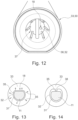
- Figure 12 shows another embodiment of a container 33 and tool 30.
- a recess 37 which serves as a receptacle or fastening for a holder of the thermometer.
- the holder can be pushed into the recess 37 and held there, for example, with a force fit.
- the recess 36 with the inner contour 32 is arranged inside the recess 37 and is accessible from the outside.
- the recess 36 can be arranged, for example, in the base of the recess 37.
- Figures 13 and 14 show schematically two ways to prevent excessive torque when the tool 30 and thermometer 1 interact.
- a section through a first housing part 11 of a thermometer located in the tool 30 is shown, with the section and image plane perpendicular to the Central longitudinal axis of the thermometer. From the inside to the outside, the first housing part 11 with the outer contour 31, an intermediate space 35 that remains free, for example, and the tool 30 with the inner contour 32 are shown.
- the area of the tool 30 that forms the inner contour is flexible, so that in the event of an excessive torque, the tool 30 is deformed, whereby the tool is moved radially outwards at least in places along the arrows 45.
- a relative rotation can take place between the first housing part 11 and the tool 30 despite the flattening 18. In other words, slippage occurs.
- the thermometer is thus protected from excessive force, particularly when screwing together, so that the stability of the thread can be ensured, for example.
- the area of the tool that forms the inner contour is made of plastic or rubber.
- the inner contour 32 of the tool 30 is shaped differently than the outer contour 31 of the first housing part 11.
- the inner contour 32 of the tool 30 is shaped differently than the outer contour 31 of the first housing part 11.
- the shaped element is also flexible, for example made of plastic or rubber.
- the shaped element is dimensioned such that it bends sideways into the gap 35 in the event of excessive torque, thus allowing relative rotation between the first housing part 11 and the tool 30, i.e. slippage.
Landscapes
- Physics & Mathematics (AREA)
- General Physics & Mathematics (AREA)
- Measuring Temperature Or Quantity Of Heat (AREA)
Applications Claiming Priority (1)
| Application Number | Priority Date | Filing Date | Title |
|---|---|---|---|
| DE102023203598.7A DE102023203598A1 (de) | 2023-04-19 | 2023-04-19 | Speisenthermometer, System und Verfahren |
Publications (1)
| Publication Number | Publication Date |
|---|---|
| EP4450937A1 true EP4450937A1 (fr) | 2024-10-23 |
Family
ID=90735469
Family Applications (1)
| Application Number | Title | Priority Date | Filing Date |
|---|---|---|---|
| EP24170393.3A Pending EP4450937A1 (fr) | 2023-04-19 | 2024-04-16 | Thermomètre alimentaire, système et procédé |
Country Status (3)
| Country | Link |
|---|---|
| EP (1) | EP4450937A1 (fr) |
| CN (1) | CN118817093A (fr) |
| DE (1) | DE102023203598A1 (fr) |
Citations (6)
| Publication number | Priority date | Publication date | Assignee | Title |
|---|---|---|---|---|
| EP0687866A1 (fr) | 1994-06-18 | 1995-12-20 | Wiesheu-Wiwa GmbH | Four pour le traitement avec chaleur des aliments solides |
| US6568848B1 (en) | 1999-09-20 | 2003-05-27 | Maverick Industries, Inc. | Wireless remote cooking thermometer system |
| CA2530089A1 (fr) * | 2004-12-20 | 2006-06-20 | Browne & Co. | Ustensile de mesure de la temperature avec afficheur de temperature detachable |
| US7075442B2 (en) | 2003-07-07 | 2006-07-11 | Mastrad Sa | Food temperature monitoring device |
| US20120225170A1 (en) * | 2011-03-04 | 2012-09-06 | Tecpoint Gmbh | Device for detecting the internal temperature of a foodstuff |
| WO2014049632A1 (fr) * | 2012-09-25 | 2014-04-03 | テルモ株式会社 | Étui de rangement pour thermomètre électronique |
-
2023
- 2023-04-19 DE DE102023203598.7A patent/DE102023203598A1/de active Pending
-
2024
- 2024-04-16 EP EP24170393.3A patent/EP4450937A1/fr active Pending
- 2024-04-18 CN CN202410468110.4A patent/CN118817093A/zh active Pending
Patent Citations (7)
| Publication number | Priority date | Publication date | Assignee | Title |
|---|---|---|---|---|
| EP0687866A1 (fr) | 1994-06-18 | 1995-12-20 | Wiesheu-Wiwa GmbH | Four pour le traitement avec chaleur des aliments solides |
| EP0687866B1 (fr) * | 1994-06-18 | 1999-04-07 | Wiesheu GmbH | Four pour le traitement avec chaleur des aliments solides |
| US6568848B1 (en) | 1999-09-20 | 2003-05-27 | Maverick Industries, Inc. | Wireless remote cooking thermometer system |
| US7075442B2 (en) | 2003-07-07 | 2006-07-11 | Mastrad Sa | Food temperature monitoring device |
| CA2530089A1 (fr) * | 2004-12-20 | 2006-06-20 | Browne & Co. | Ustensile de mesure de la temperature avec afficheur de temperature detachable |
| US20120225170A1 (en) * | 2011-03-04 | 2012-09-06 | Tecpoint Gmbh | Device for detecting the internal temperature of a foodstuff |
| WO2014049632A1 (fr) * | 2012-09-25 | 2014-04-03 | テルモ株式会社 | Étui de rangement pour thermomètre électronique |
Also Published As
| Publication number | Publication date |
|---|---|
| DE102023203598A1 (de) | 2024-10-24 |
| CN118817093A (zh) | 2024-10-22 |
Similar Documents
| Publication | Publication Date | Title |
|---|---|---|
| EP2132847A1 (fr) | Raccord de cable comprenant une contre-enveloppe ou un ecrou d'accouplement | |
| DE102014002660A1 (de) | Vorrichtung zur Aufnahme eines Temperatursensors | |
| EP2929764B1 (fr) | Boîte munie d'une articulation | |
| WO2009097842A1 (fr) | Dispositif à enfichage | |
| DE102010017732A1 (de) | Rohr-Klemmverbinder | |
| EP4450937A1 (fr) | Thermomètre alimentaire, système et procédé | |
| DE102004012417B4 (de) | Funktionsteil für einen Schraubendreher und Schraubendrehersatz | |
| DE3241677C1 (de) | Betaetigungsaufsatz fuer einen Druck-Zugschalter | |
| DE102005051226A1 (de) | Kabel- oder Schlauchverschraubung | |
| DE3545393C2 (fr) | ||
| EP1496334A1 (fr) | Boulon pour un point de mesure | |
| WO2017182028A1 (fr) | Dispositif de fixation pour fixer une plaque formant bride à un boîtier d'armoire de distribution et boîtier d'armoire de distribution correspondant | |
| DE202020002717U1 (de) | Sicherheitsventil | |
| EP0703394A1 (fr) | Collier de serrage | |
| DE102019105567A1 (de) | Drehmomentwerkzeug | |
| EP3001081B1 (fr) | Vanne équerre doté d'un volant à main | |
| DE102008058848B4 (de) | Anschlussvorrichtung mit Phasenwahl | |
| DE102013101677A1 (de) | Sicherheitsventil | |
| DE102008058947B4 (de) | Mutternschraubgerät | |
| DE10301879B3 (de) | Steckvorrichtungselement mit Montagegewinde | |
| DE3033104C2 (de) | Vorrichtung zum Anschließen eines elektrischen Leiters an eine isolierte Freileitung | |
| EP1517098B1 (fr) | soupape de radiateur | |
| WO2018108198A1 (fr) | Élément de borne pourvu d'une isolation et utilisation d'une isolation mobile pour obtenir une valeur de mesure au niveau d'un élément accumulateur | |
| DE202004002440U1 (de) | Schraubendreher mit auswechselbaren Funktionsteilen für Arbeiten an unter elektrischer Spannung stehenden Anlagen und daraus zusammengestellte Schraubendreher-Sätze | |
| DE202021100997U1 (de) | Hauptleiteranschlussklemme |
Legal Events
| Date | Code | Title | Description |
|---|---|---|---|
| PUAI | Public reference made under article 153(3) epc to a published international application that has entered the european phase |
Free format text: ORIGINAL CODE: 0009012 |
|
| STAA | Information on the status of an ep patent application or granted ep patent |
Free format text: STATUS: THE APPLICATION HAS BEEN PUBLISHED |
|
| AK | Designated contracting states |
Kind code of ref document: A1 Designated state(s): AL AT BE BG CH CY CZ DE DK EE ES FI FR GB GR HR HU IE IS IT LI LT LU LV MC ME MK MT NL NO PL PT RO RS SE SI SK SM TR |
|
| STAA | Information on the status of an ep patent application or granted ep patent |
Free format text: STATUS: REQUEST FOR EXAMINATION WAS MADE |
|
| 17P | Request for examination filed |
Effective date: 20250414 |