EP4450947A1 - Verfahren und vorrichtung zur diagnose eines radlagers - Google Patents
Verfahren und vorrichtung zur diagnose eines radlagers Download PDFInfo
- Publication number
- EP4450947A1 EP4450947A1 EP23168270.9A EP23168270A EP4450947A1 EP 4450947 A1 EP4450947 A1 EP 4450947A1 EP 23168270 A EP23168270 A EP 23168270A EP 4450947 A1 EP4450947 A1 EP 4450947A1
- Authority
- EP
- European Patent Office
- Prior art keywords
- wheel
- time
- profile
- wheel bearing
- vibration
- Prior art date
- Legal status (The legal status is an assumption and is not a legal conclusion. Google has not performed a legal analysis and makes no representation as to the accuracy of the status listed.)
- Withdrawn
Links
Images


Classifications
-
- G—PHYSICS
- G01—MEASURING; TESTING
- G01M—TESTING STATIC OR DYNAMIC BALANCE OF MACHINES OR STRUCTURES; TESTING OF STRUCTURES OR APPARATUS, NOT OTHERWISE PROVIDED FOR
- G01M13/00—Testing of machine parts
- G01M13/04—Bearings
- G01M13/045—Acoustic or vibration analysis
Definitions
- the present invention refers to a method for diagnosing a wheel bearing of a wheel of a vehicle. Moreover, the present invention refers to an apparatus that is adapted to execute the steps of a method.
- the detection of wheel bearings of vehicles can be performed by checking bearing clearances by hand. This may be followed by accelerating the wheel and listening to whether the bearing produces noise. Therefore, the assessment of bearing wear is a subjective assessment of the inspector. The manufacturer's procedures do not provide for the quantification of the measurements. Measurement results are not repeatable.
- Symptoms of bearing degradation are vibrations. When the degradation becomes more obvious by generation of noise and heat there are only a few days or in some cases only a few minutes remaining until the breakdown of the bearing.
- the US 8 125 323 B2 describes a wheel monitoring apparatus.
- the apparatus comprises a measuring and evaluation unit configured to mount to two bolts of the wheel so as to be spaced from its central axis.
- the unit includes at least one sensor configured to detect a characteristic variable for a state of the wheel bearing and at least one sensor configured to detect a pressure of the tire.
- This wheel monitoring device may monitor vibrations of the wheel bearing during travel. However, it may not be used for quick diagnoses in a repair shop. Moreover, it is necessary to permanently mount one monitoring device at each wheel of the vehicle.
- the method for diagnosing a wheel bearing of a wheel of a vehicle, especially a truck comprises accelerating the wheel to a defined velocity.
- a time-profile of a vibration of the wheel bearing is measured from the moment when the defined velocity is reached to the moment when the wheel stops.
- a wear of the wheel bearing is detected from the time-profile of the vibration.
- Different parameters of the time-profile may be evaluated to detect wear of the wheel bearing: Preferably an intensity of the vibration at the moment when the defined velocity is reached is considered when detecting the wear of the wheel bearing.
- the intensity of the vibration reaches its maximum when the defined velocity is reached. This maximum vibration is significantly higher for a worn wheel bearing than for a new wheel bearing.
- a time interval from the moment when the defined velocity is reached to the moment when the wheel stops is considered when detecting the wear of the wheel bearing.
- a new wheel bearing produces more friction than a worn wheel bearing. Therefore, the time interval becomes larger when the wheel bearing becomes worn.
- a form of the time-profile is considered when detecting the wear of the wheel bearing. If the wheel bearing is new vibrations significantly drop when the wheel begins to decelerate. Shortly before the stop of the wheel there are only very little vibrations. On the other hand, a worn wheel bearing results in vibrations that drop nearly linear over time until the wheel stops.
- a correlation of the intensity of the vibration at the moment when the defined velocity is reached, the time interval from the moment the defined velocity is reached to the moment the wheel stops and the form of the time-profile is considered when the detecting of the wheel bearing.
- This allows for a more detailed analysis of the time-profile. For example, if a wheel bearing is extremely worn it may show very high vibrations at the moment the defined velocity is reached but the vibrations will quickly decrease since the wheel bearing becomes hot and the wheel stops with in short time.
- Such a time-profile is best analyzed by a correlation of all above mentioned parameters.
- the time-profile is preferably compared to empiric reference data for wheel bearings of different wheel conditions, when detecting the wheel bearing.
- the reference data shall refer to the same time of vehicle.
- wear can also be detected if only data for a new wheel bearing is available. If the intensity of the vibration when the defined velocity is reached is at least 50 % higher than the intensity of the vibration of a new wheel bearing the wheel bearing may be considered as being worn. If the time until the wheel that has been accelerated to the defined velocity stops is especially more than 200 % of the time of a new wheel bearing the wheel bearing may be considered as been worn. When the form of the time-profile is mostly linear for at least 75 % of the time-profile the wheel bearing maybe considered as being worn.
- a recommendation whether the wheel bearing shall be replaced is generated depending on the detected wear.
- time-profiles may especially be classified in three classes. Time-profiles of the first class show that a wheel bearing is in good condition. Time-profiles in the second class show that the wheel bearing shall be replaced. Time-profiles in the third class will produce a critical alert to replace the wheel bearing.
- the recommendation may especially be communicated to a user via a human machine interface (HMI).
- HMI human machine interface
- Vibration sensors may detect vibrations as accelerations in three directions in space.
- the vibration acceleration perpendicular to the ground is especially relevant for detecting wear of the wheel bearing. It is preferable to express the intensity of the vibration by plotting it in the time-profile as a root mean square vibration acceleration. This is a square root of the area under the acceleration spectral density curve per particular to the ground.
- Accelerating the wheel to the defined velocity preferably begins with lifting the wheel from the ground. This can be done by raising the front axle of the vehicle off the ground or by lifting the whole vehicle off the ground. Then the wheel is accelerated by an accelerator, especially an electrical accelerator. The accelerator is removed from the wheel when reaching the defined velocity. After that the wheel begins to decelerate until the wheel stops.
- an accelerator especially an electrical accelerator. The accelerator is removed from the wheel when reaching the defined velocity. After that the wheel begins to decelerate until the wheel stops.
- the velocity of the wheel may be preferably detected by using velocity information from the vehicle. Especially this information is received from a velocity sensor that is permanently installed in the vehicle system.
- the time-profile of the vibration is measured using a sensor that is removably mounted on the steering knuckle of the wheel.
- the same sensor can be used again and again to successively detect wear of the wheel bearings of booth front wheels of several vehicles.
- an apparatus for diagnosing a wheel bearing of a wheel of a vehicle is adapted to execute the steps of the method.
- the apparatus may comprise an accelerator.
- the apparatus may comprise a vibration sensor that is adapted to be removably mounted on a steering knuckle of a wheel.
- the apparatus may comprise a computer device adaptor to analyze a velocity-time-profile.
- Figure 1 shows a vehicle 10 that is a truck.
- the wheel bearing of its left front wheel 11 shell be diagnosed using a method according to an embodiment of the invention.
- the method is implemented as a computer program in a computer device 30.
- the computer device 30 is linked by a first data link 31 to an electric accelerator 32.
- the accelerator 32 has an accelerator wheel 33 that contacts the front wheel 11 of the vehicle 10.
- a second data link 34 links the computer device 30 to a speed information system (not shown) of the vehicle 10.
- FIG. 2 shows that the computer device 30 is further linked by a third data link 35 to a vibration sensor 36.
- the vibration sensor 36 is removably mounted on a steering knuckle 13 of the wheel 11 behind the wheel bearing 12. It detects vibrations in the direction of ride x, perpendicular to the ground y, and parallel to the wheel-axis z.
- the vibration sensor 36 maybe a BCM0001 sensor or a BCM0002 sensor (BALLUFF GmbH, Germany).
- the computer device 30 maybe a CMTK condition monitoring tool kit or an PMSYS portable monitoring system (BALLUFF GmbH, Germany).
- the vehicle 10 is lifted 41 by the car lift 21.
- the accelerator 31 is moved 42 so that its accelerator wheel 33 contacts the front wheel 11.
- the front wheel 11 is accelerated 43 by the accelerator 32 until a defined velocity of 90 km/h is reached 44.
- the accelerator 32 is removed 45 from the wheel 11.
- the wheel 11 begins to decelerate measuring 46 of a time-profile of a vibration of the wheel bearing 12 is started using the sensor 36. The measurement is continued until the wheel 11 stops 47.
- wear of the wheel bearing 12 is detected 48 from the vibration-time-profile.
- a recommendation whether the wheel bearing 12 shall be replaced is generated 49 and communicated via a display of the computer device 30. After that the method is ended 50.
- An intensity as a vibration is plotted in the time-profile as a root mean square vibration acceleration a-RMS Y per perpendicular to the ground 20 over time t.
- a-RMS Y root mean square vibration acceleration
- the intensity of the vibration when the defined velocity is reached, the time interval from reaching the defined velocity to the stop of wheel 11 and the form of the time-profile a correlated.
- they are compared to reference data for a new wheel bearing 12 for the same vehicle type.
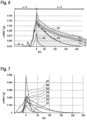
- Figure 4 shows a reference time-profile 61 and a measured time-profile 62 for a vehicle 10.
- the reference time-profile 61 was measured at a mileage of 55 km and the measured time-profile 62 was measured at a mileage of 396,647 km.
- the vibration of the reference time-profile 61 reaches a maximum of 0,10 g the measured time-profile 62 reaches a maximum of 0,27 g.
- the wheel 11 needs seventy seconds to stop after the accelerator 72 has been removed the wheel 11 of the measured time-profile 62 needs two hundred forty seconds to stop.
- the form of the reference time-profile 61 shows a quick decrease of vibrations shortly after the wheel 11 has begun to decelerate while the vibrations remain nearly unchanged for the rest of the time until the wheel 11 stops.
- the vibrations of the measured time-profile 62 decreases in a nearly linear manner.
- the maximum intensity of vibration, the time until the wheel 11 stops and the form of the time-profile 61, 62 all show that the diagnosed wheel bearing 12 is worn in comparison to the reference wheel bearing 12.
- a reference time-profile 63 for the right wheel bearing 12 is compared to the measured time-profile 64.
- the intensity of the vibration of the reference time-profile 63 is 0,08 g in contrast to 0,16 g for the measured time-profile 64.
- the time until the wheel 11 stops is seventy seconds in the reference time-profile 63 it is two hundred seconds in the measured time-profile 64.
- the form of the reference time-profile 63 is mainly similar to that of the reference time-profile 61 of the left front wheel bearing 12 and the form of the measured time-profile 64 is mainly the same as for the left front wheel bearing 12. Therefore, the right wheel bearing 12 is also worn.
- FIG. 6 shows how time-profiles may be classified in different classes in an embodiment of the inventive method.
- the first class 71 comprises wheel bearings 12 that are in good condition.
- the second class 72 comprises wheel bearings 12 that should be replaced.
- the third class 73 comprises wheel bearings 12 that are no longer safe and shall urgently be replaced.
- Time t is counted from the moment when the acceleration a of the wheel 11 drops below zero because the wheel 11 starts to decelerate.
- Three measured time-profiles 65 to 67 are shown.
- the first time-profile 65 is a time-profile of a new wheel bearing 12. It is well within the first class 71.
- the second time-profile 66 is a time-profile of a wheel bearing 12 with a mileage of 40,000 km. It is still within the first class 71.
- the third time-profile 67 is a time-profile of a wheel bearing 12 with a mileage of 800,000 km. This time-profile 67 is within the third class 73. When such a high wear of a wheel bearing 12 is detected the computer device 30 will output a critical alert.
- Figure 7 shows time-profiles 81 to 87 of several diagnosed wheel bearings 12.
- the first time-profile 81 was measured from a new wheel bearing 12.
- the second time-profile 82 was measured from a left wheel bearing with a mileage of 369,000 km.
- the third time-profile 83 was measured from a right wheel bearing 12 with a mileage of 369,000 km.
- the fourth time-profile 84 was measured from a left wheel bearing with a mileage of 861,000 km.
- the fifth time-profile 85 was measured from a right wheel bearing with a mileage of 861,000 km.
- the sixth time-profile was measured from a right wheel bearing with a mileage of 694000 km.
- the seventh time-profile was measured from a left wheel bearing 12 with a mileage of 694,000 km.
- All wheel bearings 12 according to the first five time-profiles 81 to 85 are still in good condition.
- the wheel bearings 12 according to the sixth time-profile 86 and the seventh time-profile 87 shall be replaced. While the wear of the wheel bearing 12 according to the sixth time-profile 86 cannot be concluded from the time until the wheel 11 stopped or from the maximum intensity alone it can be seen from a correlation of this information. A wheel bearing with such high maximum vibration should need much more time until the wheel 11 stops.
- the seventh wheel bearing 12 can be diagnosed as being worn because the maximum vibration in its time-profile 87 is very high and its wheel 11 stops even earlier then the wheel 11 with a new wheel bearing 12 according to the first time-profile 81.
Landscapes
- Physics & Mathematics (AREA)
- Acoustics & Sound (AREA)
- General Physics & Mathematics (AREA)
- Testing Of Devices, Machine Parts, Or Other Structures Thereof (AREA)
Priority Applications (1)
| Application Number | Priority Date | Filing Date | Title |
|---|---|---|---|
| EP23168270.9A EP4450947A1 (de) | 2023-04-17 | 2023-04-17 | Verfahren und vorrichtung zur diagnose eines radlagers |
Applications Claiming Priority (1)
| Application Number | Priority Date | Filing Date | Title |
|---|---|---|---|
| EP23168270.9A EP4450947A1 (de) | 2023-04-17 | 2023-04-17 | Verfahren und vorrichtung zur diagnose eines radlagers |
Publications (1)
| Publication Number | Publication Date |
|---|---|
| EP4450947A1 true EP4450947A1 (de) | 2024-10-23 |
Family
ID=86052438
Family Applications (1)
| Application Number | Title | Priority Date | Filing Date |
|---|---|---|---|
| EP23168270.9A Withdrawn EP4450947A1 (de) | 2023-04-17 | 2023-04-17 | Verfahren und vorrichtung zur diagnose eines radlagers |
Country Status (1)
| Country | Link |
|---|---|
| EP (1) | EP4450947A1 (de) |
Citations (4)
| Publication number | Priority date | Publication date | Assignee | Title |
|---|---|---|---|---|
| US8125323B2 (en) | 2007-09-20 | 2012-02-28 | Aktiebolaget Skf | Wheel monitoring device |
| KR20200082910A (ko) * | 2018-12-31 | 2020-07-08 | 주식회사 일진글로벌 | 고장 진단 장치 및 이러한 고장 진단 장치를 구비하는 차량용 휠베어링 |
| DE102020202921B3 (de) * | 2020-03-06 | 2021-03-25 | Zf Friedrichshafen Ag | Verfahren zum Auswuchten eines Rades |
| CN114636554A (zh) * | 2022-03-15 | 2022-06-17 | 联合汽车电子有限公司 | 电驱动系统轴承故障监测方法和装置 |
-
2023
- 2023-04-17 EP EP23168270.9A patent/EP4450947A1/de not_active Withdrawn
Patent Citations (4)
| Publication number | Priority date | Publication date | Assignee | Title |
|---|---|---|---|---|
| US8125323B2 (en) | 2007-09-20 | 2012-02-28 | Aktiebolaget Skf | Wheel monitoring device |
| KR20200082910A (ko) * | 2018-12-31 | 2020-07-08 | 주식회사 일진글로벌 | 고장 진단 장치 및 이러한 고장 진단 장치를 구비하는 차량용 휠베어링 |
| DE102020202921B3 (de) * | 2020-03-06 | 2021-03-25 | Zf Friedrichshafen Ag | Verfahren zum Auswuchten eines Rades |
| CN114636554A (zh) * | 2022-03-15 | 2022-06-17 | 联合汽车电子有限公司 | 电驱动系统轴承故障监测方法和装置 |
Similar Documents
| Publication | Publication Date | Title |
|---|---|---|
| JP6087163B2 (ja) | タイヤユニフォミティマシンを特性化するためのシステムおよびその特性化を使用する方法 | |
| KR101829645B1 (ko) | 철도 차량 모니터링 장치 및 이를 이용한 모니터링 방법 | |
| JP4091083B2 (ja) | タイヤ内部故障検知装置およびタイヤ内部故障検知方法 | |
| JP5027260B2 (ja) | タイヤ空気圧分類ベースのタイヤ空気圧監視 | |
| EP3713780B1 (de) | Verfahren und system zur überwachung eines parameters im zusammenhang mit einem reifen während des fahrens eines fahrzeugs | |
| CN112533771B (zh) | 轮胎损坏检测系统和方法 | |
| JP2014530347A (ja) | 自動車用シャシシステムにおける構成部品の欠陥診断方法及び装置 | |
| US20030080857A1 (en) | Process and system for determining the onset of tread rubber separations of a pneumatic tire on a vehicle | |
| KR20130064344A (ko) | 자동차 휠 밸런스 진단 장치 및 그 휠 밸런스 진단 방법 | |
| US7272536B2 (en) | Failure warning for a tire among a plurality of tires | |
| KR20230165225A (ko) | 섀시 구성 요소의 상태를 결정하기 위한 방법 및 차량 시스템 | |
| Nowakowski et al. | Diagnostics of the drive shaft bearing based on vibrations in the high-frequency range as a part of the vehicle's self-diagnostic system | |
| CN118711278B (zh) | 基于高精度测量的专用车辆载荷监控方法及系统 | |
| KR102198725B1 (ko) | 자동차 주행안전부품 자가진단 장치 | |
| KR101408001B1 (ko) | 차량용 타이어 공기압 모니터링 장치 및 방법 | |
| EP4450947A1 (de) | Verfahren und vorrichtung zur diagnose eines radlagers | |
| Dimitrov et al. | Investigation of acceleration and brake deceleration of light vehicles | |
| CN111289913A (zh) | 一种基于物联网的新能源汽车故障诊断装置 | |
| CN113758720B (zh) | 一种卡车行驶抖动检测方法 | |
| JP5112730B2 (ja) | タイヤ耐久力性能予測方法、タイヤ耐久力性能予測装置、及びタイヤ耐久力性能予測プログラム | |
| JP2003519041A (ja) | 走行運転中における車両特性の検査方法 | |
| CN121347172A (zh) | 测试轮胎的方法和装置 | |
| CN111458055A (zh) | 一种重卡轮毂轴承温度监测传感器试验机及试验方法 | |
| KR102518652B1 (ko) | 간접식 타이어 압력 모니터링 시스템 및 방법 | |
| JP2007064877A (ja) | タイヤの故障発生検知方法およびタイヤの故障発生検知装置 |
Legal Events
| Date | Code | Title | Description |
|---|---|---|---|
| PUAI | Public reference made under article 153(3) epc to a published international application that has entered the european phase |
Free format text: ORIGINAL CODE: 0009012 |
|
| STAA | Information on the status of an ep patent application or granted ep patent |
Free format text: STATUS: REQUEST FOR EXAMINATION WAS MADE |
|
| 17P | Request for examination filed |
Effective date: 20230417 |
|
| AK | Designated contracting states |
Kind code of ref document: A1 Designated state(s): AL AT BE BG CH CY CZ DE DK EE ES FI FR GB GR HR HU IE IS IT LI LT LU LV MC ME MK MT NL NO PL PT RO RS SE SI SK SM TR |
|
| P01 | Opt-out of the competence of the unified patent court (upc) registered |
Free format text: CASE NUMBER: APP_5630/2025 Effective date: 20250203 |
|
| STAA | Information on the status of an ep patent application or granted ep patent |
Free format text: STATUS: THE APPLICATION IS DEEMED TO BE WITHDRAWN |
|
| 18D | Application deemed to be withdrawn |
Effective date: 20251101 |