EP4450962A1 - Interface universelle entre un élément de montage de tête d'essai et une tête d'essai - Google Patents
Interface universelle entre un élément de montage de tête d'essai et une tête d'essai Download PDFInfo
- Publication number
- EP4450962A1 EP4450962A1 EP23168841.7A EP23168841A EP4450962A1 EP 4450962 A1 EP4450962 A1 EP 4450962A1 EP 23168841 A EP23168841 A EP 23168841A EP 4450962 A1 EP4450962 A1 EP 4450962A1
- Authority
- EP
- European Patent Office
- Prior art keywords
- test head
- interface
- sensor arrangement
- receiving element
- optical
- Prior art date
- Legal status (The legal status is an assumption and is not a legal conclusion. Google has not performed a legal analysis and makes no representation as to the accuracy of the status listed.)
- Pending
Links
Images
Classifications
-
- G—PHYSICS
- G01—MEASURING; TESTING
- G01N—INVESTIGATING OR ANALYSING MATERIALS BY DETERMINING THEIR CHEMICAL OR PHYSICAL PROPERTIES
- G01N27/00—Investigating or analysing materials by the use of electric, electrochemical, or magnetic means
- G01N27/26—Investigating or analysing materials by the use of electric, electrochemical, or magnetic means by investigating electrochemical variables; by using electrolysis or electrophoresis
- G01N27/28—Electrolytic cell components
- G01N27/283—Means for supporting or introducing electrochemical probes
- G01N27/286—Power or signal connectors associated therewith
-
- G—PHYSICS
- G01—MEASURING; TESTING
- G01D—MEASURING NOT SPECIALLY ADAPTED FOR A SPECIFIC VARIABLE; ARRANGEMENTS FOR MEASURING TWO OR MORE VARIABLES NOT COVERED IN A SINGLE OTHER SUBCLASS; TARIFF METERING APPARATUS; MEASURING OR TESTING NOT OTHERWISE PROVIDED FOR
- G01D11/00—Component parts of measuring arrangements not specially adapted for a specific variable
- G01D11/28—Structurally-combined illuminating devices
-
- G—PHYSICS
- G01—MEASURING; TESTING
- G01D—MEASURING NOT SPECIALLY ADAPTED FOR A SPECIFIC VARIABLE; ARRANGEMENTS FOR MEASURING TWO OR MORE VARIABLES NOT COVERED IN A SINGLE OTHER SUBCLASS; TARIFF METERING APPARATUS; MEASURING OR TESTING NOT OTHERWISE PROVIDED FOR
- G01D11/00—Component parts of measuring arrangements not specially adapted for a specific variable
-
- G—PHYSICS
- G01—MEASURING; TESTING
- G01D—MEASURING NOT SPECIALLY ADAPTED FOR A SPECIFIC VARIABLE; ARRANGEMENTS FOR MEASURING TWO OR MORE VARIABLES NOT COVERED IN A SINGLE OTHER SUBCLASS; TARIFF METERING APPARATUS; MEASURING OR TESTING NOT OTHERWISE PROVIDED FOR
- G01D11/00—Component parts of measuring arrangements not specially adapted for a specific variable
- G01D11/24—Housings ; Casings for instruments
-
- G—PHYSICS
- G01—MEASURING; TESTING
- G01D—MEASURING NOT SPECIALLY ADAPTED FOR A SPECIFIC VARIABLE; ARRANGEMENTS FOR MEASURING TWO OR MORE VARIABLES NOT COVERED IN A SINGLE OTHER SUBCLASS; TARIFF METERING APPARATUS; MEASURING OR TESTING NOT OTHERWISE PROVIDED FOR
- G01D11/00—Component parts of measuring arrangements not specially adapted for a specific variable
- G01D11/24—Housings ; Casings for instruments
- G01D11/245—Housings for sensors
-
- G—PHYSICS
- G01—MEASURING; TESTING
- G01D—MEASURING NOT SPECIALLY ADAPTED FOR A SPECIFIC VARIABLE; ARRANGEMENTS FOR MEASURING TWO OR MORE VARIABLES NOT COVERED IN A SINGLE OTHER SUBCLASS; TARIFF METERING APPARATUS; MEASURING OR TESTING NOT OTHERWISE PROVIDED FOR
- G01D21/00—Measuring or testing not otherwise provided for
- G01D21/02—Measuring two or more variables by means not covered by a single other subclass
-
- H—ELECTRICITY
- H02—GENERATION; CONVERSION OR DISTRIBUTION OF ELECTRIC POWER
- H02J—ELECTRIC POWER NETWORKS; CIRCUIT ARRANGEMENTS OR SYSTEMS FOR SUPPLYING OR DISTRIBUTING ELECTRIC POWER; SYSTEMS FOR STORING ELECTRIC ENERGY
- H02J50/00—Circuit arrangements or systems for wireless supply or distribution of electric power
- H02J50/10—Circuit arrangements or systems for wireless supply or distribution of electric power using inductive coupling
- H02J50/12—Circuit arrangements or systems for wireless supply or distribution of electric power using inductive coupling of the resonant type
-
- H—ELECTRICITY
- H02—GENERATION; CONVERSION OR DISTRIBUTION OF ELECTRIC POWER
- H02J—ELECTRIC POWER NETWORKS; CIRCUIT ARRANGEMENTS OR SYSTEMS FOR SUPPLYING OR DISTRIBUTING ELECTRIC POWER; SYSTEMS FOR STORING ELECTRIC ENERGY
- H02J50/00—Circuit arrangements or systems for wireless supply or distribution of electric power
- H02J50/80—Circuit arrangements or systems for wireless supply or distribution of electric power involving the exchange of data, concerning supply or distribution of electric power, between transmitting devices and receiving devices
-
- H—ELECTRICITY
- H04—ELECTRIC COMMUNICATION TECHNIQUE
- H04B—TRANSMISSION
- H04B10/00—Transmission systems employing electromagnetic waves other than radio-waves, e.g. infrared, visible or ultraviolet light, or employing corpuscular radiation, e.g. quantum communication
- H04B10/40—Transceivers
-
- H—ELECTRICITY
- H04—ELECTRIC COMMUNICATION TECHNIQUE
- H04B—TRANSMISSION
- H04B5/00—Near-field transmission systems, e.g. inductive or capacitive transmission systems
- H04B5/40—Near-field transmission systems, e.g. inductive or capacitive transmission systems characterised by components specially adapted for near-field transmission
-
- H—ELECTRICITY
- H04—ELECTRIC COMMUNICATION TECHNIQUE
- H04Q—SELECTING
- H04Q9/00—Arrangements in telecontrol or telemetry systems for selectively calling a substation from a main station, in which substation desired apparatus is selected for applying a control signal thereto or for obtaining measured values therefrom
-
- H—ELECTRICITY
- H04—ELECTRIC COMMUNICATION TECHNIQUE
- H04W—WIRELESS COMMUNICATION NETWORKS
- H04W4/00—Services specially adapted for wireless communication networks; Facilities therefor
- H04W4/80—Services using short range communication, e.g. near-field communication [NFC], radio-frequency identification [RFID] or low energy communication
-
- G—PHYSICS
- G01—MEASURING; TESTING
- G01D—MEASURING NOT SPECIALLY ADAPTED FOR A SPECIFIC VARIABLE; ARRANGEMENTS FOR MEASURING TWO OR MORE VARIABLES NOT COVERED IN A SINGLE OTHER SUBCLASS; TARIFF METERING APPARATUS; MEASURING OR TESTING NOT OTHERWISE PROVIDED FOR
- G01D2213/00—Indexing scheme relating to constructional details of indicators
-
- G—PHYSICS
- G08—SIGNALLING
- G08C—TRANSMISSION SYSTEMS FOR MEASURED VALUES, CONTROL OR SIMILAR SIGNALS
- G08C23/00—Non-electrical signal transmission systems, e.g. optical systems
- G08C23/04—Non-electrical signal transmission systems, e.g. optical systems using light waves, e.g. infrared
-
- H—ELECTRICITY
- H02—GENERATION; CONVERSION OR DISTRIBUTION OF ELECTRIC POWER
- H02J—ELECTRIC POWER NETWORKS; CIRCUIT ARRANGEMENTS OR SYSTEMS FOR SUPPLYING OR DISTRIBUTING ELECTRIC POWER; SYSTEMS FOR STORING ELECTRIC ENERGY
- H02J50/00—Circuit arrangements or systems for wireless supply or distribution of electric power
- H02J50/005—Mechanical details of housing or structure aiming to accommodate the power transfer means, e.g. mechanical integration of coils, antennas or transducers into emitting or receiving devices
-
- H—ELECTRICITY
- H04—ELECTRIC COMMUNICATION TECHNIQUE
- H04B—TRANSMISSION
- H04B5/00—Near-field transmission systems, e.g. inductive or capacitive transmission systems
- H04B5/20—Near-field transmission systems, e.g. inductive or capacitive transmission systems characterised by the transmission technique; characterised by the transmission medium
- H04B5/24—Inductive coupling
-
- H—ELECTRICITY
- H04—ELECTRIC COMMUNICATION TECHNIQUE
- H04Q—SELECTING
- H04Q2209/00—Arrangements in telecontrol or telemetry systems
- H04Q2209/40—Arrangements in telecontrol or telemetry systems using a wireless architecture
- H04Q2209/43—Arrangements in telecontrol or telemetry systems using a wireless architecture using wireless personal area networks [WPAN], e.g. 802.15, 802.15.1, 802.15.4, Bluetooth® or Zigbee®
-
- H—ELECTRICITY
- H04—ELECTRIC COMMUNICATION TECHNIQUE
- H04Q—SELECTING
- H04Q2209/00—Arrangements in telecontrol or telemetry systems
- H04Q2209/80—Arrangements in the sub-station, i.e. sensing device
- H04Q2209/88—Providing power supply at the sub-station
Definitions
- the invention relates to a sensor arrangement for measuring properties of liquids and gases, comprising a test head and a test head receiving element, wherein the test head and the test head receiving element can be detachably connected to one another, wherein the sensor arrangement has a galvanically isolated interface formed by an inductive interface and/or a galvanically coupled interface, wherein the galvanically isolated interface and/or the galvanically coupled interface serves exclusively for energy transmission from the test head receiving element to the test head.
- sensors are often used in which a test head or sensor is detachably paired with a corresponding receiving element, which in turn is firmly connected to an evaluation unit via a cable.
- Different test heads can be connected to the receiving element, such as pH sensors, redox sensors, chlorine sensors, turbidity sensors, to name just a few.
- all types of sensors that can be used to analyse liquids and gases can be connected to the receiving element.
- Such sensors have to be cleaned, calibrated and adjusted frequently, which is why the two-part design is an advantage and the test head can be easily removed from the receiving element.
- different test heads can be coupled to the receiving element, which means that the same evaluation unit with a permanently connected receiving element can be used to analyse different properties of the liquid or gas, and only the test head needs to be replaced.
- the EP 1 565 898 A1 discloses a modular evaluation unit in which a sensor module and an electronic module have an inductive interface that serves for energy as well as data transmission, wherein the electronic module is connected to the transmitting and receiving station via a supply line for energy supply and the data exchange takes place inductively.
- the DE 10 2019 118 712 discloses a sensor that is connected to a measuring system via a galvanically isolated connection.
- the data transmission between the sensor and the measuring system takes place via a first inductive interface and the energy transmission between the measuring system and the sensor takes place via a second inductive interface.
- the sensor arrangement has at least one optical interface or at least one Bluetooth interface for bidirectional data transmission between the test head and the test head receiving element.
- the sensor arrangement according to the invention is used to measure properties of liquids and gases.
- the sensor arrangement includes a test head that is designed as a sensor. All possible types of sensors that are suitable for analyzing liquids and gases can be used.
- the sensor arrangement also includes a test head receiving element that can be releasably connected to the test head.
- the sensor arrangement according to the invention preferably has a galvanically isolated interface for energy transmission, formed by an inductive interface.
- the sensor arrangement according to the invention has a galvanically coupled interface for energy transmission, which is preferably formed by a metallic contact between the test head and the test head receiving element.
- a metallically conductive sheet is arranged on the test head and the test head receiving element, which when the two components of the Sensor arrangement contact with each other.
- This enables an even higher energy transfer, e.g. for energy-intensive sensor elements.
- the galvanically coupled interface can also be designed differently; a galvanic element is preferably arranged on the test head and one on the test head receiving element and can also be detachably connected to each other again if such a galvanically coupled interface is provided on the sensor arrangement according to the invention.
- the sensor arrangement may have a galvanically isolated interface, via an inductive interface, as well as a galvanically coupled interface, with both interfaces each serving exclusively for energy transfer, both when both are arranged on the sensor arrangement and when only one of the interfaces is arranged on the sensor arrangement according to the invention.
- the sensor arrangement according to the invention has at least one optical interface between the test head and the test head receiving element for bidirectional data transmission or at least one Bluetooth interface between the test head and the test head receiving element for bidirectional data transmission.
- bidirectional data transmission also includes two unidirectional data transmissions.
- the Bluetooth interface on the test head and on the test head receiving element is suitable for data transmission with mobile communication devices such as mobile phones, computers or tablets, as well as for communication with measuring devices, control systems or calibration devices.
- a preferred embodiment consists in that a transmitter and a receiver of the optical interface are arranged on the test head and on the test head receiving element, thereby ensuring bidirectional data transmission.
- a transmitter and a receiver are arranged on both the test head and the test head receiving element and the corresponding complementary elements are arranged opposite one another on the other component of the sensor arrangement.
- An optical bidirectional data transmission also has the advantage that the quality of the data is checked. This means that if the received data does not correspond to the data sent or exceeds a tolerance in the deviation of the signal quality, this is detected and a corresponding message is sent. occurs, for example the test head needs to be cleaned or it needs to be readjusted.
- circuit boards that form the inductive interface are arranged parallel to each other.
- At least one circuit board of the inductive interface is arranged on the test head and at least one further circuit board of the inductive interface is arranged on the test head receiving element.
- a further advantageous embodiment has been shown to be when two circuit boards of the inductive interface are arranged on the test head and on the test head receiving element, which enables a higher energy transfer. This creates two inductive interfaces.
- the circuit boards of the inductive interface are aligned flatly with one another. It is advantageous if the circuit boards of the inductive interface run parallel to the longitudinal axis of the sensor arrangement.
- circuit boards of the inductive interface run parallel to the front side of the test head and the test head receiving element.
- the transmitter of the optical interface is formed by an LED. This also enables a compact and energy-saving implementation of an optical interface.
- test head and the test head receiving element are cylindrical and can be plugged into each other, rotated or screwed.
- the optical interfaces are arranged on the front of the test head and on the test head receiving element. This enables a compact design of the sensor arrangement.
- the optical interfaces are arranged on surfaces of the test head and the test head receiving element that run parallel to the longitudinal axis and to one another. As a result, the transmitters and receivers of the optical interface are aligned at right angles to the longitudinal axis.
- the Bluetooth interface is arranged instead of the optical interface arrangement.
- a preferred embodiment has been shown to be when the transmitters and receivers of the optical interface are arranged axially opposite each other. This allows the distance between the transmitter and receiver to be optimally adjusted and provides a high data transmission and good data quality.
- optical interfaces are arranged on the front side of the test head and the test head receiving element and the transmitters and receivers are placed on a separate circuit board that is aligned parallel to the longitudinal axis.
- the transmitter and receiver of the optical interfaces are arranged on a different circuit board than the inductive interface.
- the transmitter and receiver of the test head as well as the sensor and receiver of the test head receiving element are each arranged on a different circuit board than the conductor tracks of the inductive interface in the test head as well as in the test head receiving element.
- the sensor arrangement according to the invention has light guides for better guidance of the optical signal. This enables a more flexible arrangement of the transmitter and receiver of the optical interface.
- the signal from the transmitter of an LED can be transmitted by means of light guides.
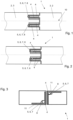
- the in Fig. 1 The drawing shown shows a schematic representation of a sensor arrangement 1 with test head 2 and test head receiving element 3, which end of the two parts is designed how, whether with grooves or springs is not important, which is why both ends each have both reference symbols.
- the Fig. 1 and 2 The embodiments shown show ends of the test head 2 and the test head receiving element 3 which have a tongue and groove connection and engage with each other.
- the sensor arrangement 1 has inductive interfaces 4 which are formed by conductor tracks on circuit boards 4.
- the Figures 1 and 2 The embodiments shown have two galvanically isolated interfaces 4 running parallel to the longitudinal axis 10.
- the interfaces 4 are formed by circuit boards 4 running parallel to each other and to the longitudinal axis 10, which have conductor tracks for exclusively inductive energy transmission.
- FIG. 1 and 2 are two pairs of such circuit boards 4 Of course, only one pair can form the inductive interface, or additional circuit boards can be used for the inductive interface.
- the optical interfaces 5 are arranged on the front side and their alignment is parallel to the longitudinal axis, which serve for data transmission. In order to ensure bidirectional data transmission, two optical interfaces 5 are to be provided.
- the optical interfaces 5 can be arranged as in Fig. 2 shown, can also be arranged on surfaces parallel to the longitudinal axis 10 on the test head 2 and on the test head receiving element 3.
- the optical interface 5 is in Fig. 2 perpendicular to the longitudinal axis is sufficient.
- a Bluetooth interface 8 can be used instead of the optical interface 5.
- Fig. 3 shows a schematic representation of a sensor arrangement 1 according to the invention in which a light guide 9 is used to transmit the optical signal of the optical interface 5.
- the signal from the transmitter 6 is projected by means of the light guide 9 in such a way that the receiver 7 can detect it without any problem.
- the circuit boards 4 of the inductive interface are parallel to the front sides of the test head 2 and the test head receiving element 3.
- the transmitter of the optical interface 5, preferably an LED, is coupled to a light guide 9. It has proven advantageous if the transmitter and the receiver 7 are arranged on a different circuit board 4 than the conductor tracks of the inductive interface 4.
- circuit board 11 of the transmitter 6 and receiver 7 are at a 90° angle to the circuit board of the inductive interface 4.
- the arrangement of the circuit boards 4, 11 in Fig.3 is only an example and other arrangements in which the transmitter and receiver are on a separate circuit board or not on the same circuit board as the conductor tracks of the inductive interface are conceivable.
- No galvanically coupled interface is shown, but it goes without saying that this is formed by conventional metallic elements, of which at least one is arranged on the test head 2 and at least one on the test head receiving element 3.
Landscapes
- Engineering & Computer Science (AREA)
- Physics & Mathematics (AREA)
- General Physics & Mathematics (AREA)
- Computer Networks & Wireless Communication (AREA)
- Signal Processing (AREA)
- Chemical & Material Sciences (AREA)
- Power Engineering (AREA)
- Health & Medical Sciences (AREA)
- Life Sciences & Earth Sciences (AREA)
- Biochemistry (AREA)
- Molecular Biology (AREA)
- Chemical Kinetics & Catalysis (AREA)
- Electrochemistry (AREA)
- Analytical Chemistry (AREA)
- Electromagnetism (AREA)
- General Health & Medical Sciences (AREA)
- Immunology (AREA)
- Pathology (AREA)
- Investigating Or Analysing Materials By Optical Means (AREA)
- Investigating Or Analysing Materials By The Use Of Chemical Reactions (AREA)
- Arrangements For Transmission Of Measured Signals (AREA)
- Near-Field Transmission Systems (AREA)
Priority Applications (16)
| Application Number | Priority Date | Filing Date | Title |
|---|---|---|---|
| EP23168841.7A EP4450962A1 (fr) | 2023-04-20 | 2023-04-20 | Interface universelle entre un élément de montage de tête d'essai et une tête d'essai |
| EP23189230.8A EP4451515A1 (fr) | 2023-04-20 | 2023-08-02 | Transfert d'énergie sans fil |
| EP23193982.8A EP4451516A1 (fr) | 2023-04-20 | 2023-08-29 | Optimisation d'un rendement en boucle fermee |
| CA3231062A CA3231062A1 (en) | 2023-04-20 | 2024-03-05 | Wireless power transfer |
| MX2024002821A MX2024002821A (es) | 2023-04-20 | 2024-03-05 | Transferencia inalambrica de energia |
| MX2024002823A MX2024002823A (es) | 2023-04-20 | 2024-03-05 | Interfaz universal |
| CA3231069A CA3231069A1 (en) | 2023-04-20 | 2024-03-05 | Universal interface |
| TW113108557A TW202510461A (zh) | 2023-04-20 | 2024-03-08 | 無線電力傳輸 |
| TW113108555A TW202445127A (zh) | 2023-04-20 | 2024-03-08 | 通用介面 |
| AU2024201946A AU2024201946A1 (en) | 2023-04-20 | 2024-03-26 | Wireless power transfer |
| AU2024202081A AU2024202081A1 (en) | 2023-04-20 | 2024-04-02 | Universal interface |
| US18/638,906 US20240353243A1 (en) | 2023-04-20 | 2024-04-18 | Universal interface |
| US18/638,855 US20240356385A1 (en) | 2023-04-20 | 2024-04-18 | Wireless power transfer |
| CN202410475470.7A CN118826884A (zh) | 2023-04-20 | 2024-04-19 | 通用接口 |
| JP2024068329A JP2024155886A (ja) | 2023-04-20 | 2024-04-19 | ワイヤレスエネルギ伝送 |
| JP2024068326A JP2024155885A (ja) | 2023-04-20 | 2024-04-19 | ユニバーサルインタフェース |
Applications Claiming Priority (1)
| Application Number | Priority Date | Filing Date | Title |
|---|---|---|---|
| EP23168841.7A EP4450962A1 (fr) | 2023-04-20 | 2023-04-20 | Interface universelle entre un élément de montage de tête d'essai et une tête d'essai |
Publications (1)
| Publication Number | Publication Date |
|---|---|
| EP4450962A1 true EP4450962A1 (fr) | 2024-10-23 |
Family
ID=86096047
Family Applications (2)
| Application Number | Title | Priority Date | Filing Date |
|---|---|---|---|
| EP23168841.7A Pending EP4450962A1 (fr) | 2023-04-20 | 2023-04-20 | Interface universelle entre un élément de montage de tête d'essai et une tête d'essai |
| EP23189230.8A Pending EP4451515A1 (fr) | 2023-04-20 | 2023-08-02 | Transfert d'énergie sans fil |
Family Applications After (1)
| Application Number | Title | Priority Date | Filing Date |
|---|---|---|---|
| EP23189230.8A Pending EP4451515A1 (fr) | 2023-04-20 | 2023-08-02 | Transfert d'énergie sans fil |
Country Status (8)
| Country | Link |
|---|---|
| US (1) | US20240353243A1 (fr) |
| EP (2) | EP4450962A1 (fr) |
| JP (1) | JP2024155885A (fr) |
| CN (1) | CN118826884A (fr) |
| AU (1) | AU2024202081A1 (fr) |
| CA (1) | CA3231069A1 (fr) |
| MX (1) | MX2024002823A (fr) |
| TW (1) | TW202445127A (fr) |
Citations (7)
| Publication number | Priority date | Publication date | Assignee | Title |
|---|---|---|---|---|
| GB2365122A (en) * | 2000-05-31 | 2002-02-13 | Abb Instrumentation Ltd | Analysis device |
| EP1206012A2 (fr) * | 2000-11-07 | 2002-05-15 | Endress + Hauser Conducta Gesellschaft für Mess- und Regeltechnik mbH + Co. | Connecteur pour connecter une ligne de transmision à au mois un senseur |
| EP1565898A2 (fr) | 2002-11-28 | 2005-08-24 | Endress + Hauser Conducta GmbH + Co. KG | Transducteur de mesure modulaire a capteur galvaniquement separe |
| DE102015210880A1 (de) * | 2015-06-15 | 2016-12-15 | Sentronic GmbH Gesellschaft für optische Meßsysteme | Messeinrichtung zur Bestimmung physikalischer Eigenschaften, chemischer Eigenschaften, biologischer Eigenschaften und/oder von Stoffen der Umgebung wenigstens eines Aufnehmers oder des wenigstens einen Aufnehmers als Bestandteil der Messeinrichtung |
| EP3168953A1 (fr) * | 2015-11-13 | 2017-05-17 | TE Connectivity Germany GmbH | Système de connecteur sans contact ayant une rétroaction à partir du côté secondaire |
| US20190132655A1 (en) * | 2016-03-11 | 2019-05-02 | Dae Yoon Scale Industrial Co., Ltd. | Sensor module, connector module, and water quality measuring device comprising the same |
| DE102019118712A1 (de) | 2019-07-10 | 2021-01-14 | Endress+Hauser Conducta Gmbh+Co. Kg | Feldgerät und Gegenstelle |
Family Cites Families (11)
| Publication number | Priority date | Publication date | Assignee | Title |
|---|---|---|---|---|
| NZ565234A (en) * | 2008-01-18 | 2010-11-26 | Telemetry Res Ltd | Selectable resonant frequency transcutaneous energy transfer system |
| KR20100130215A (ko) * | 2008-03-17 | 2010-12-10 | 파우워매트 엘티디. | 유도송전장치 |
| KR101912692B1 (ko) * | 2012-07-06 | 2018-10-29 | 엘지전자 주식회사 | 무선 전력 전송에서의 주파수를 주기적으로 변경하는 방법 및 장치 |
| KR101776991B1 (ko) * | 2014-12-03 | 2017-09-08 | 현대자동차주식회사 | 무선 전력 전송 장치 및 방법과 무선 전력 전송에 이용되는 공진주파수 검출 방법 |
| KR20170076170A (ko) * | 2015-12-24 | 2017-07-04 | 엘지이노텍 주식회사 | 다중 모드를 지원하는 무선 전력 송신기 |
| US10107774B2 (en) * | 2016-03-18 | 2018-10-23 | Simonds Precision Products, Inc. | Optically interfaced fuel characteristic sensor |
| US10122416B2 (en) * | 2016-12-30 | 2018-11-06 | Panosense Inc. | Interface for transferring power and data between a non-rotating body and a rotating body |
| CN208110365U (zh) * | 2017-06-12 | 2018-11-16 | 特莎有限公司 | 用于光学探针的铰接头、坐标测量系统和工具保持架 |
| US11059380B2 (en) * | 2017-09-21 | 2021-07-13 | Utah State University | Dynamic inductive wireless power transmitter system with a power transmitter module |
| EP4302059B1 (fr) * | 2021-03-01 | 2025-12-10 | Hahn-Schickard-Gesellschaft für angewandte Forschung e. V. | Dispositif de mesure de déformations, de contraintes, de forces et/ou de couples dans une pluralité d'axes |
| US20240106270A1 (en) * | 2022-09-23 | 2024-03-28 | Apple Inc. | Inductive coil assemblies for electronic devices and accessories |
-
2023
- 2023-04-20 EP EP23168841.7A patent/EP4450962A1/fr active Pending
- 2023-08-02 EP EP23189230.8A patent/EP4451515A1/fr active Pending
-
2024
- 2024-03-05 CA CA3231069A patent/CA3231069A1/en active Pending
- 2024-03-05 MX MX2024002823A patent/MX2024002823A/es unknown
- 2024-03-08 TW TW113108555A patent/TW202445127A/zh unknown
- 2024-04-02 AU AU2024202081A patent/AU2024202081A1/en active Pending
- 2024-04-18 US US18/638,906 patent/US20240353243A1/en active Pending
- 2024-04-19 JP JP2024068326A patent/JP2024155885A/ja active Pending
- 2024-04-19 CN CN202410475470.7A patent/CN118826884A/zh active Pending
Patent Citations (7)
| Publication number | Priority date | Publication date | Assignee | Title |
|---|---|---|---|---|
| GB2365122A (en) * | 2000-05-31 | 2002-02-13 | Abb Instrumentation Ltd | Analysis device |
| EP1206012A2 (fr) * | 2000-11-07 | 2002-05-15 | Endress + Hauser Conducta Gesellschaft für Mess- und Regeltechnik mbH + Co. | Connecteur pour connecter une ligne de transmision à au mois un senseur |
| EP1565898A2 (fr) | 2002-11-28 | 2005-08-24 | Endress + Hauser Conducta GmbH + Co. KG | Transducteur de mesure modulaire a capteur galvaniquement separe |
| DE102015210880A1 (de) * | 2015-06-15 | 2016-12-15 | Sentronic GmbH Gesellschaft für optische Meßsysteme | Messeinrichtung zur Bestimmung physikalischer Eigenschaften, chemischer Eigenschaften, biologischer Eigenschaften und/oder von Stoffen der Umgebung wenigstens eines Aufnehmers oder des wenigstens einen Aufnehmers als Bestandteil der Messeinrichtung |
| EP3168953A1 (fr) * | 2015-11-13 | 2017-05-17 | TE Connectivity Germany GmbH | Système de connecteur sans contact ayant une rétroaction à partir du côté secondaire |
| US20190132655A1 (en) * | 2016-03-11 | 2019-05-02 | Dae Yoon Scale Industrial Co., Ltd. | Sensor module, connector module, and water quality measuring device comprising the same |
| DE102019118712A1 (de) | 2019-07-10 | 2021-01-14 | Endress+Hauser Conducta Gmbh+Co. Kg | Feldgerät und Gegenstelle |
Also Published As
| Publication number | Publication date |
|---|---|
| CA3231069A1 (en) | 2025-07-02 |
| AU2024202081A1 (en) | 2024-11-07 |
| JP2024155885A (ja) | 2024-10-31 |
| TW202445127A (zh) | 2024-11-16 |
| CN118826884A (zh) | 2024-10-22 |
| MX2024002823A (es) | 2024-11-08 |
| US20240353243A1 (en) | 2024-10-24 |
| EP4451515A1 (fr) | 2024-10-23 |
Similar Documents
| Publication | Publication Date | Title |
|---|---|---|
| DE3538687A1 (de) | Testeinrichtung | |
| EP4450962A1 (fr) | Interface universelle entre un élément de montage de tête d'essai et une tête d'essai | |
| DE10255741A1 (de) | Modularer Messumformer mit galvanisch getrennten Messfühler | |
| DE102004034248A1 (de) | Elektronische Schaltung mit galvanisch getrennten Baugruppen | |
| DE2741585B2 (de) | Einschubsteckverbindung fur Lichtwellenleiter | |
| DE60304684T2 (de) | Radiofrequenzstromerzeugung und leistungsmessung | |
| EP1807502A1 (fr) | Dispositif pour agiter des agents | |
| EP3987367B1 (fr) | Dispositif de mesure | |
| DE29624219U1 (de) | Bussystem | |
| DE3702527C2 (fr) | ||
| EP1772707B1 (fr) | Dispositif de mesure | |
| WO2018050422A1 (fr) | Adaptation de la puissance d'émission et/ou de réception dans un appareil de terrain | |
| EP0837332A2 (fr) | Dispositif pour la détermination de la constante d'un appareil dans un dispositif de contrÔle intégré dans un véhicule | |
| DE10154710A1 (de) | Vorrichtung und Verfahren zur Detektion der Position eines Targets | |
| EP0769747A1 (fr) | Dispositif d'interfaçage pour lecteur de cartes magnétiques | |
| AT413606B (de) | Vorrichtung zum messen der qualität eines geschlachteten tieres oder von lebensmitteln | |
| DE102013000707B4 (de) | Messvorrichtung | |
| DE102018131214A1 (de) | Verfahren zur Konfiguration einer Erfassungsvorrichtung | |
| DE102010026341A1 (de) | Ultraschallsensor für Wertdokumente, Wandlermodul für diesen und Verfahren zur Herstellung des Ultraschallsensors | |
| DE202024106767U1 (de) | Zellspannungsmessvorrichtung für Brennstoffzellen | |
| DE4333245A1 (de) | Datenerfassungs- und Auswertevorrichtung | |
| DE3590302T1 (de) | Meßdaten-Übertragungssystem und Verbindungsaufbau für das System | |
| DE3732740A1 (de) | Anordnung mit einer zentralen steuereinheit und mehreren teilnehmern | |
| DE102018104924B4 (de) | Vorrichtung mit einer Funkkommunikationseinheit und einer Schalteinheit | |
| DE9317946U1 (de) | Schnittstellenkabel für Datenendeinrichtungen und Prüfeinrichtung |
Legal Events
| Date | Code | Title | Description |
|---|---|---|---|
| PUAI | Public reference made under article 153(3) epc to a published international application that has entered the european phase |
Free format text: ORIGINAL CODE: 0009012 |
|
| STAA | Information on the status of an ep patent application or granted ep patent |
Free format text: STATUS: THE APPLICATION HAS BEEN PUBLISHED |
|
| AK | Designated contracting states |
Kind code of ref document: A1 Designated state(s): AL AT BE BG CH CY CZ DE DK EE ES FI FR GB GR HR HU IE IS IT LI LT LU LV MC ME MK MT NL NO PL PT RO RS SE SI SK SM TR |
|
| STAA | Information on the status of an ep patent application or granted ep patent |
Free format text: STATUS: REQUEST FOR EXAMINATION WAS MADE |
|
| 17P | Request for examination filed |
Effective date: 20250422 |