EP4451003A1 - Agencement de capteur et procédé de fonctionnement d'un agencement de capteur - Google Patents
Agencement de capteur et procédé de fonctionnement d'un agencement de capteur Download PDFInfo
- Publication number
- EP4451003A1 EP4451003A1 EP23168177.6A EP23168177A EP4451003A1 EP 4451003 A1 EP4451003 A1 EP 4451003A1 EP 23168177 A EP23168177 A EP 23168177A EP 4451003 A1 EP4451003 A1 EP 4451003A1
- Authority
- EP
- European Patent Office
- Prior art keywords
- sensor arrangement
- alignment element
- alignment
- sensor
- scanning plane
- Prior art date
- Legal status (The legal status is an assumption and is not a legal conclusion. Google has not performed a legal analysis and makes no representation as to the accuracy of the status listed.)
- Pending
Links
Images


Classifications
-
- G—PHYSICS
- G01—MEASURING; TESTING
- G01S—RADIO DIRECTION-FINDING; RADIO NAVIGATION; DETERMINING DISTANCE OR VELOCITY BY USE OF RADIO WAVES; LOCATING OR PRESENCE-DETECTING BY USE OF THE REFLECTION OR RERADIATION OF RADIO WAVES; ANALOGOUS ARRANGEMENTS USING OTHER WAVES
- G01S7/00—Details of systems according to groups G01S13/00, G01S15/00, G01S17/00
- G01S7/48—Details of systems according to groups G01S13/00, G01S15/00, G01S17/00 of systems according to group G01S17/00
- G01S7/4804—Auxiliary means for detecting or identifying lidar signals or the like, e.g. laser illuminators
-
- G—PHYSICS
- G01—MEASURING; TESTING
- G01S—RADIO DIRECTION-FINDING; RADIO NAVIGATION; DETERMINING DISTANCE OR VELOCITY BY USE OF RADIO WAVES; LOCATING OR PRESENCE-DETECTING BY USE OF THE REFLECTION OR RERADIATION OF RADIO WAVES; ANALOGOUS ARRANGEMENTS USING OTHER WAVES
- G01S7/00—Details of systems according to groups G01S13/00, G01S15/00, G01S17/00
- G01S7/48—Details of systems according to groups G01S13/00, G01S15/00, G01S17/00 of systems according to group G01S17/00
- G01S7/497—Means for monitoring or calibrating
- G01S7/4972—Alignment of sensor
Definitions
- Such sensor arrangements include an area distance sensor with which object monitoring is carried out.
- the light beams of the transmitter are deflected by means of a deflection unit so that they are periodically guided within a flat monitoring area and thus scan a scanning plane.
- the area distance sensor Before starting work, the area distance sensor must be adjusted and aligned so that the scanning plane scanned by the light beams of the area distance sensor is aligned in a specified target position.
- an area distance sensor is aligned on a machine or vehicle so that the scanning plane runs in a horizontal plane. and is therefore aligned parallel to the floor of a hall or similar on which the machine is standing or the vehicle is driving.
- Active alignment units it is known to use active alignment units to align the area distance sensor. Active means that the alignment unit has several active components that receive the light rays, whereupon the corresponding display means are activated.
- An example of this is a column with a linear arrangement of photodiodes, to which light-emitting diodes are assigned as display means.
- the alignment unit designed in this way is set up so that the longitudinal axis of the column runs in a vertical direction. Depending on the orientation of the area distance sensor, its light rays hit a specific photodiode, which is visualized with the display means. A user can thus check the current orientation of the area distance sensor.
- the disadvantage here is that the alignment unit with its large number of active optical and electronic components is structurally complex and expensive.
- the discrete arrangement of the photodiodes limits the resolution when detecting the light rays, so that the accuracy of the alignment of the area distance sensor is correspondingly limited.
- the invention is based on the object of enabling an exact adjustment of an area distance sensor with the lowest possible construction and cost effort.
- the invention relates to a sensor arrangement with a surface distance sensor, with a transmitter emitting light beams and a receiver receiving light beams.
- the light beams are periodically guided in a scanning plane.
- An evaluation unit is used to determine distances between objects depending on the reception signals from the receiver.
- At least one alignment element is present, which is arranged at an angle to the scanning plane so that its height protrudes above the scanning plane.
- the alignment element has a contrast pattern which changes in a unique manner over the height of the alignment element.
- the distance of the alignment element and the amplitude or signal strength curve of the reception signals when scanning the contrast pattern with the light beams are evaluated as a measure of the orientation of the scanning plane based on the reception signals from the receiver.
- the invention also relates to a corresponding method.
- At least one alignment element is assigned to the area distance sensor for its adjustment.
- the alignment element forms a passive element, i.e. it has no active optical components or electronic components.
- the alignment element can therefore be manufactured simply and inexpensively.
- the alignment element can be a single object that is placed on the floor, for example.
- the alignment element can alternatively be attached firmly as a flat, thin surface or film to another object or a wall. It can therefore be integrated easily and flexibly.
- the alignment element has a contrast pattern that has a structure that is clearly location-dependent in the height direction of the alignment element.
- the alignment element is scanned with the light beams of the area distance sensor, whereby a measure of the alignment of the area distance sensor and its scanning plane is obtained based solely on the measured values of the area distance sensor.
- the area distance sensor is used to determine the distance to the alignment element.
- the contrast pattern of the alignment element is recorded by determining the amplitude curve of the received signals during scanning of the alignment element and its contrast pattern and evaluating this in the evaluation unit.
- the contrast pattern has a clear variation in the height direction of the alignment element, a different amplitude curve is always obtained for scanning the contrast pattern with the light beams at different heights.
- the determined amplitude curve in the evaluation unit can be used to determine exactly at which height the light beams hit the contrast pattern of the alignment element, i.e. this provides a clear measure of the position of the scanning plane and thus of the current alignment of the area distance sensor.
- the height of the position of the beam exit on the surface distance sensor is measured as a reference point for the scanning plane, as is also common practice with active alignment aids in the state of the art.
- the determination of this reference point is usually known from the design or attachment of the sensor or is easily measurable.
- the target height of the scanning plane on the alignment element corresponds to the exit height on the surface distance sensor.
- the sensor arrangement has only one alignment element.
- the received signals generated when scanning the alignment elements are then evaluated in the evaluation unit.
- the detection of the alignment elements detects tilts of the scanning plane in the height direction of the alignment elements and, in this respect, a plane spanned by the alignment elements.
- the alignment elements particularly advantageously span a horizontal target plane.
- the alignment elements are oriented perpendicular to the horizontal target plane.
- This configuration allows the scanning plane to be aligned particularly well to a horizontal target plane.
- a display unit which is assigned to the area distance sensor.
- the display unit shows the alignment of the scanning plane relative to the alignment element(s).
- the display unit shows the current alignment, which was determined by scanning the alignment element(s).
- the deviation of the current alignment of the surface distance sensor with respect to a target position is also advantageously displayed.
- the display unit can be used to indicate tilting of the surface distance sensors with respect to a target position.
- information or instructions can be displayed as to how or in which direction a user must tilt the orientation of the surface distance sensor in order to reach a target position.
- the achievement of the desired target position within a selected tolerance can be displayed.
- Alphanumeric values can be output on the display unit. It is particularly advantageous if the display unit is designed as a graphic display.
- the display unit can form a separate unit and be integrated, for example, in a PC, laptop, tablet or smartphone, whereby the separate unit is connected to the area distance sensors via a data connection.
- the display unit can also be integrated into the area distance sensor.
- the or each alignment element in the evaluation unit can be identified by means of its contrast pattern.
- the contrast pattern then has a unique structure that distinguishes the alignment element from other objects to be detected. This means that the alignment element can be identified during the measuring operation of the optical sensor or area distance sensor without additional measures.
- the contrast pattern of the or each alignment element comprises retroreflective elements on a diffusely reflecting background.
- a dark background is provided for convenience.
- the highly reflective retroreflective elements can be reliably distinguished from the weakly reflective background because received signals originating from the retroreflective elements have much larger amplitudes than received signals originating from the background.
- the contrast pattern has two retroreflective strips extending over the entire height of the alignment elements, which run at an angle of inclination to one another.
- the inclination of the two retroreflective strips relative to each other results in a different local pattern at each height of the alignment element, which is recorded when the light beams are scanned.
- the amplitude curve of the received signals together with the determined distance value thus provides a clear statement about the height at which the contrast pattern was scanned.
- the retroreflective strip thus provides a reference line that marks the beginning and end of the contrast pattern and the alignment element so that its position can be determined.
- the retroreflective strips are conveniently rectangular in shape.
- the retroreflective elements consist of retroreflective foils.
- the foils can be easily glued to the background of the alignment element.
- a further embodiment provides a film that can be applied in the corresponding height-dependent pattern to any vertical flat surface in the room (e.g. wall, furniture).
- a background for the alignment element may then no longer be necessary, as the film can form the contrasting pattern on any existing background.
- a predefined width or limitation of the flat surface to which the alignment element is applied is also not necessary, as the retroreflective strip marks the beginning and/or end of the glued-on integrated alignment aid.
- the area distance sensor can advantageously be designed as a safety sensor that can be used in the field of safety technology, in particular in the field of personal protection.
- a safety sensor can be used to monitor danger areas on hazardous systems.
- the safety sensor has a fail-safe structure for this purpose. This can be achieved, for example, by a redundant evaluation unit.
- a two-channel evaluation unit with two computer units that check each other cyclically can be provided.
- fail-safe output structures can be provided for the fail-safe output of object detection signals. These can be formed in the form of two-channel outputs.
- the area distance sensor designed as a safety sensor can be used to monitor the protective field.
- a binary switching signal is generated in the evaluation unit depending on the received signals from the receiver, the switching states of which indicate whether an object is in the protective field or not.
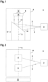
- Figure 1 shows a first embodiment of an area distance sensor 1, i.e. a scanning distance sensor, the components of which are housed in a housing 2.
- the optical sensor has a transmitter 4 emitting light beams 3 and a receiver 5 receiving light beams 3 with an upstream receiving optics 6.
- the transmitter 4 emits light beams 3 in the form of light pulses.
- the light rays 3 are reflected at a detecting object 7, whereby the corresponding light travel time of the light pulses to the object 7 and back to the area distance sensor 1 is evaluated for the distance determinations.
- the transmitter 4 and the receiver 5 are arranged stationary in the housing 2.
- the area distance sensor 1 detects objects in a flat detection area by periodically deflecting the light beams 3 by means of a deflection unit 8.
- the deflection unit 8 is motor-driven and comprises a deflection mirror 10 which can be rotated about an axis of rotation 9 and on which the light beams 3 are deflected.
- the light beams 3 reflected back from the object 7 are guided to the receiver 5 via the deflection unit 8.
- Figure 2 shows a variant of the area distance sensor 1 according to Figure 1
- the periodic deflection of the light beams 3 is achieved by arranging the transmitter 4 and the receiver 5 in a measuring head 11 which can be rotated about an axis of rotation 9, the measuring head 11 being rotatably mounted on a base 12.
- a protective field monitoring is particularly advantageous.
- a flat protective field is specified within the monitoring area.
- the area distance sensor 1 then generates a binary switching signal as an object detection signal, the switching states of which indicate whether an object 7 is within the protective field or not.
- the area distance sensors 1 are designed in accordance with Figures 1 and 2 designed as safety sensors and have a fail-safe structure, which can be implemented, for example, by a redundant evaluation unit in the form of two processors that cyclically monitor each other. Furthermore, a fail-safe, in particular two-channel output is provided for outputting the object detection signal.
- the Figures 3a, 3b show a first embodiment of the sensor arrangement 100 according to the invention with a surface distance sensor 1 according to the Figures 1 or 2, wherein the area distance sensor 1 is arranged on a machine 14, which is set up on a floor 15 of a hall, in an inclination-adjustable manner by means of an articulated connection 13.
- the area distance sensor 1 can also be attached to a driverless transport system (FTS) or an automated guided vehicle (AGV).
- FTS driverless transport system
- AGV automated guided vehicle
- the horizontal alignment of the scanning plane in the desired position is particularly important due to its proximity to the floor 15 and the alignment aid 16 according to the invention is particularly advantageous.
- the articulated connection 13 shown here represents a possible embodiment of a mounting or adjustment device for the area distance sensor 1, which allows a modification of the scanning plane.
- the sensor arrangement 100 has an alignment element 16.
- the alignment element 16 is attached to a not shown Holder mounted so that it is oriented perpendicular to the floor 15, ie the height direction of the alignment element 16 runs in the vertical direction.
- Figure 3 a shows the area distance sensor 1 in a misaligned position in which the scanning plane is inclined downwards. In this position, the alignment element 16 is scanned at a first height position I using the light beams 3 of the area distance sensor 1.
- Figure 3 shows the area distance sensor 1 in its target position after adjustment, in which the scanning plane runs in a horizontal plane. In this target position, the alignment element 16 is scanned in a second height position II using the light beams 3 of the area distance sensor 1.
- the alignment element 16 When the alignment element 16 is scanned with the area distance sensor 1, on the one hand the distance of the alignment element 16 to the area distance sensor 1 is detected and on the other hand the amplitude curve of the received signals is determined, whereby the contrast pattern is detected at the respective altitude.
- the contrast pattern has a clear variation in the height direction, a different amplitude curve of the received signal is always obtained when scanning each height position of the alignment element 16, which together with the distance value provides a clear measure of the position of the scanning plane relative to the alignment element 16.
- the deviation of the position of the area distance sensor 1 from the target position is thus quantitatively determined, which is visualized on a display unit.
- a user can thus adjust the area distance sensor 1 accordingly using the articulated connection 13, whereby in the present embodiment a one-dimensional pivoting movement is carried out in a vertical plane with the articulated connection 13.
- the display unit can be integrated in the area distance sensor 1.
- the display unit can be provided in an external unit.
- the external unit is a smartphone 17, the display of which is used as a display unit.
- the smartphone 17 is connected to the area distance sensor 1 via a data connection, in particular a radio link.
- Figure 4 shows an extension of the embodiment of the Figures 3a, 3b , wherein the sensor arrangement 100 is shown in a plan view from above.
- Three preferably identical alignment elements 16 are provided, which are arranged one behind the other at a distance in the scanning direction A of the light beams 3 of the area distance sensor 1.
- the alignment elements 16 span a horizontal plane which defines the target position for the scanning plane of the area distance sensor 1.
- the received signals generated during the scanning of the alignment elements 16 are evaluated in the evaluation unit.
- tilting of the scanning plane in the height direction of the alignment elements 16 and with respect to a plane spanned by the alignment elements 16 is determined by detecting the alignment elements 16.
- the surface distance sensor 1 can then be adjusted in two spatial directions on the articulated connection.
- the tilts are again displayed on the display unit of the smartphone 17 so that a user can correct the misalignment of the area distance sensor 1.
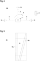
- Figure 5 shows a concrete design of a contrast pattern of the alignment element 16 of the Figures 3a, 3b , 4 . As from Figure 5 As can be seen, the alignment element 16 is rectangular.
- the contrast pattern is formed by applying, in particular gluing, two rectangular retroreflective strips 18a, 18b in the form of foils onto a dark, diffusely reflecting background 19 on the surface of the alignment element 16 facing the area distance sensor 1.
- the first retroreflective strip 18a runs along a lateral edge of the alignment element 16 in a vertical direction and marks the beginning of the alignment element 16.
- the second retroreflective strip 18b runs at an angle inclined to the first retroreflective strip 18a. Both retroreflective strips 18a, 18b extend over the entire height of the alignment element 16.
- the retroreflective strips 18a, 18b formed in this way result in a contrast pattern that clearly varies in the height direction of the alignment element 16. If the light rays 3 are guided over the retroreflective strips 18a, 18b, amplitudes or signal strengths S result, maximum values of the amplitudes S of the received signals, which are considerably greater than the amplitude values when the light rays 3 are guided over the background 19 of the alignment element 16.
- FIG. 6a, 6b This is in the Figures 6a, 6b illustrated.
- the Figures 6a, 6b show the measured values of the amplitudes S of the received signals depending on the deflection position D of the light beams 3.
- Figure 6a shows the amplitude curve of the received signals when the contrast pattern is scanned at altitude I with the area distance sensor 1 misaligned, as in Figure 3a shown.
- the amplitude curve has two maxima 20, 21, which are created by scanning the retroreflective strips 18a, 18b. Since the retroreflective strips 18a, 18b are close to each other at altitude I, the distance 22 between the maxima 20, 21 is small.
- Figure 6a shows the amplitude curve of the received signals when the contrast pattern is scanned at altitude II with adjusted area distance sensors 1, as in Figure 3b shown.
- the amplitude curve again has two maxima 20', 21', which are created by scanning the retroreflective strips 18a, 18b. Since the retroreflective strips 18a, 18b are further apart at altitude II, the distance 22' between the maxima 20', 21' is larger.
- the amplitude curve of the received signals together with the determined distance of the alignment elements 16 thus provides a clear measure of the degree of misalignment of the area distance sensor 1, so that the adjustment of the area distance sensor 1 can be carried out using these measured values.
Landscapes
- Engineering & Computer Science (AREA)
- Physics & Mathematics (AREA)
- Computer Networks & Wireless Communication (AREA)
- General Physics & Mathematics (AREA)
- Radar, Positioning & Navigation (AREA)
- Remote Sensing (AREA)
- Optics & Photonics (AREA)
- Length Measuring Devices By Optical Means (AREA)
Priority Applications (3)
| Application Number | Priority Date | Filing Date | Title |
|---|---|---|---|
| EP23168177.6A EP4451003A1 (fr) | 2023-04-17 | 2023-04-17 | Agencement de capteur et procédé de fonctionnement d'un agencement de capteur |
| PCT/EP2024/059438 WO2024217905A1 (fr) | 2023-04-17 | 2024-04-08 | Agencement de capteur et procédé de fonctionnement d'un agencement de capteur |
| CN202480026137.6A CN121039527A (zh) | 2023-04-17 | 2024-04-08 | 传感器装置和用于传感器装置的运行方法 |
Applications Claiming Priority (1)
| Application Number | Priority Date | Filing Date | Title |
|---|---|---|---|
| EP23168177.6A EP4451003A1 (fr) | 2023-04-17 | 2023-04-17 | Agencement de capteur et procédé de fonctionnement d'un agencement de capteur |
Publications (1)
| Publication Number | Publication Date |
|---|---|
| EP4451003A1 true EP4451003A1 (fr) | 2024-10-23 |
Family
ID=86052034
Family Applications (1)
| Application Number | Title | Priority Date | Filing Date |
|---|---|---|---|
| EP23168177.6A Pending EP4451003A1 (fr) | 2023-04-17 | 2023-04-17 | Agencement de capteur et procédé de fonctionnement d'un agencement de capteur |
Country Status (3)
| Country | Link |
|---|---|
| EP (1) | EP4451003A1 (fr) |
| CN (1) | CN121039527A (fr) |
| WO (1) | WO2024217905A1 (fr) |
Citations (2)
| Publication number | Priority date | Publication date | Assignee | Title |
|---|---|---|---|---|
| WO2021021869A1 (fr) * | 2019-07-30 | 2021-02-04 | Brain Corporation | Systèmes et procédés d'étalonnage de capteurs d'émission de lumière non visible à l'aide de cibles d'alignement |
| DE102019128437A1 (de) * | 2019-10-22 | 2021-04-22 | Valeo Schalter Und Sensoren Gmbh | Kalibriervorrichtung zur Kalibrierung wenigstens einer optischen Detektionsvorrichtung |
-
2023
- 2023-04-17 EP EP23168177.6A patent/EP4451003A1/fr active Pending
-
2024
- 2024-04-08 WO PCT/EP2024/059438 patent/WO2024217905A1/fr not_active Ceased
- 2024-04-08 CN CN202480026137.6A patent/CN121039527A/zh active Pending
Patent Citations (2)
| Publication number | Priority date | Publication date | Assignee | Title |
|---|---|---|---|---|
| WO2021021869A1 (fr) * | 2019-07-30 | 2021-02-04 | Brain Corporation | Systèmes et procédés d'étalonnage de capteurs d'émission de lumière non visible à l'aide de cibles d'alignement |
| DE102019128437A1 (de) * | 2019-10-22 | 2021-04-22 | Valeo Schalter Und Sensoren Gmbh | Kalibriervorrichtung zur Kalibrierung wenigstens einer optischen Detektionsvorrichtung |
Also Published As
| Publication number | Publication date |
|---|---|
| CN121039527A (zh) | 2025-11-28 |
| WO2024217905A1 (fr) | 2024-10-24 |
Similar Documents
| Publication | Publication Date | Title |
|---|---|---|
| EP3260885B1 (fr) | Capteur optoélectronique et procédé de détection d'objets | |
| EP3136127B1 (fr) | Capteur telemetrique et procede comprenant un capteur telemetrique | |
| DE69516871T2 (de) | Verfahren zum lokaliseren eines trieders im raum | |
| EP0596330B1 (fr) | Arrangement pour mesurer les oscillations d'une charge de grue | |
| EP1947477B1 (fr) | Capteur de triangulation doté d'une détermination d'éloignement à partir de la position et de la forme de la tache lumineuse | |
| EP1517117A1 (fr) | Méthode et système pour la détermination de la position actuelle d'un appareil de postionement | |
| WO2012110343A1 (fr) | Procédé de localisation autonome d'un véhicule motorisé sans conducteur | |
| DE4422497A1 (de) | Optoelektronische Vorrichtung zum Erfassen von Gegenständen in einem Überwachungsbereich | |
| EP2565699A2 (fr) | Capteur optoélectronique et un procédé pour détecter des objets dans une zone de surveillance | |
| WO2003087873A1 (fr) | Determination de l'orientation d'un capteur optoelectronique | |
| EP3739287A1 (fr) | Dispositif de mesure | |
| DE10026711B4 (de) | Positionsüberwachungsvorrichtung und -verfahren | |
| EP3208511B1 (fr) | Dispositif de surveillance d'une zone de surveillance d'un véhicule sans conducteur | |
| EP1921469A2 (fr) | Agencement de capteur optoélectrique et procédé d'ajustement d'un agencement de capteur optoélectrique | |
| EP1756515B1 (fr) | Appareil de marquage | |
| WO2022152463A1 (fr) | Procédé d'étalonnage d'un scanner laser et installation technique | |
| EP4451003A1 (fr) | Agencement de capteur et procédé de fonctionnement d'un agencement de capteur | |
| DE3611896C2 (fr) | ||
| EP3309520A1 (fr) | Système de mesure d'angle destiné à déterminer un angle de rotation | |
| EP1329691B1 (fr) | Procédé et dispositif pour la localisation automatique de cibles | |
| EP3415951B1 (fr) | Capteur optique | |
| DE69423971T2 (de) | Apparat zum messen der dimensionen von grossen objekten | |
| EP1959271A1 (fr) | Agencement de capteur optoélectrique et procédé de vérification du mode de fonctionnement et/ou de l'ajustement d'un agencement de capteur optoélectronique | |
| DE102017103791B4 (de) | Optoelektronischer Sensor und Verfahren zur Erfassung von Objekten | |
| DE102020124704B4 (de) | Vorrichtung und Verfahren zur Erfassung einer räumlichen Position eines Körpers |
Legal Events
| Date | Code | Title | Description |
|---|---|---|---|
| PUAI | Public reference made under article 153(3) epc to a published international application that has entered the european phase |
Free format text: ORIGINAL CODE: 0009012 |
|
| STAA | Information on the status of an ep patent application or granted ep patent |
Free format text: STATUS: REQUEST FOR EXAMINATION WAS MADE |
|
| 17P | Request for examination filed |
Effective date: 20231115 |
|
| AK | Designated contracting states |
Kind code of ref document: A1 Designated state(s): AL AT BE BG CH CY CZ DE DK EE ES FI FR GB GR HR HU IE IS IT LI LT LU LV MC ME MK MT NL NO PL PT RO RS SE SI SK SM TR |
|
| P01 | Opt-out of the competence of the unified patent court (upc) registered |
Free format text: CASE NUMBER: APP_58675/2024 Effective date: 20241028 |