EP4454590A2 - Interface électrique pour bras de robot chirurgical - Google Patents
Interface électrique pour bras de robot chirurgical Download PDFInfo
- Publication number
- EP4454590A2 EP4454590A2 EP24172789.0A EP24172789A EP4454590A2 EP 4454590 A2 EP4454590 A2 EP 4454590A2 EP 24172789 A EP24172789 A EP 24172789A EP 4454590 A2 EP4454590 A2 EP 4454590A2
- Authority
- EP
- European Patent Office
- Prior art keywords
- interface
- end effector
- robot arm
- electrical interface
- face
- Prior art date
- Legal status (The legal status is an assumption and is not a legal conclusion. Google has not performed a legal analysis and makes no representation as to the accuracy of the status listed.)
- Pending
Links
- 230000002093 peripheral effect Effects 0.000 claims abstract description 42
- 239000012636 effector Substances 0.000 claims abstract description 41
- 238000009413 insulation Methods 0.000 claims description 2
- 238000001356 surgical procedure Methods 0.000 description 25
- 210000000988 bone and bone Anatomy 0.000 description 22
- 210000000707 wrist Anatomy 0.000 description 19
- 230000013011 mating Effects 0.000 description 15
- 238000005516 engineering process Methods 0.000 description 10
- 238000003384 imaging method Methods 0.000 description 10
- 238000000034 method Methods 0.000 description 10
- 230000006870 function Effects 0.000 description 8
- 238000005286 illumination Methods 0.000 description 6
- 230000003595 spectral effect Effects 0.000 description 6
- 238000001228 spectrum Methods 0.000 description 6
- 230000008569 process Effects 0.000 description 5
- 210000004872 soft tissue Anatomy 0.000 description 5
- 230000000295 complement effect Effects 0.000 description 4
- 238000010292 electrical insulation Methods 0.000 description 4
- 230000003287 optical effect Effects 0.000 description 4
- 230000005855 radiation Effects 0.000 description 4
- 210000001519 tissue Anatomy 0.000 description 4
- 238000001914 filtration Methods 0.000 description 3
- 230000004075 alteration Effects 0.000 description 2
- 230000008901 benefit Effects 0.000 description 2
- 230000005540 biological transmission Effects 0.000 description 2
- 230000037237 body shape Effects 0.000 description 2
- 238000001514 detection method Methods 0.000 description 2
- 210000000887 face Anatomy 0.000 description 2
- 239000007943 implant Substances 0.000 description 2
- 210000003127 knee Anatomy 0.000 description 2
- 239000004973 liquid crystal related substance Substances 0.000 description 2
- 230000011664 signaling Effects 0.000 description 2
- 230000001360 synchronised effect Effects 0.000 description 2
- 239000003826 tablet Substances 0.000 description 2
- 238000002604 ultrasonography Methods 0.000 description 2
- XUIMIQQOPSSXEZ-UHFFFAOYSA-N Silicon Chemical compound [Si] XUIMIQQOPSSXEZ-UHFFFAOYSA-N 0.000 description 1
- 238000009825 accumulation Methods 0.000 description 1
- 210000003484 anatomy Anatomy 0.000 description 1
- 230000003190 augmentative effect Effects 0.000 description 1
- 238000004364 calculation method Methods 0.000 description 1
- 238000002591 computed tomography Methods 0.000 description 1
- 230000008878 coupling Effects 0.000 description 1
- 238000010168 coupling process Methods 0.000 description 1
- 238000005859 coupling reaction Methods 0.000 description 1
- 230000001186 cumulative effect Effects 0.000 description 1
- 238000013479 data entry Methods 0.000 description 1
- 238000010586 diagram Methods 0.000 description 1
- 239000011521 glass Substances 0.000 description 1
- 230000006872 improvement Effects 0.000 description 1
- 238000002329 infrared spectrum Methods 0.000 description 1
- 238000009434 installation Methods 0.000 description 1
- 230000003993 interaction Effects 0.000 description 1
- 239000000463 material Substances 0.000 description 1
- 230000007246 mechanism Effects 0.000 description 1
- 230000000399 orthopedic effect Effects 0.000 description 1
- 230000001902 propagating effect Effects 0.000 description 1
- 230000001681 protective effect Effects 0.000 description 1
- 238000002271 resection Methods 0.000 description 1
- 238000002432 robotic surgery Methods 0.000 description 1
- 239000000523 sample Substances 0.000 description 1
- -1 server Substances 0.000 description 1
- 229910052710 silicon Inorganic materials 0.000 description 1
- 239000010703 silicon Substances 0.000 description 1
- 210000004233 talus Anatomy 0.000 description 1
- 230000036962 time dependent Effects 0.000 description 1
- 238000011883 total knee arthroplasty Methods 0.000 description 1
- 230000001052 transient effect Effects 0.000 description 1
- 239000013598 vector Substances 0.000 description 1
Images


Classifications
-
- A—HUMAN NECESSITIES
- A61—MEDICAL OR VETERINARY SCIENCE; HYGIENE
- A61B—DIAGNOSIS; SURGERY; IDENTIFICATION
- A61B34/00—Computer-aided surgery; Manipulators or robots specially adapted for use in surgery
- A61B34/30—Surgical robots
-
- A—HUMAN NECESSITIES
- A61—MEDICAL OR VETERINARY SCIENCE; HYGIENE
- A61B—DIAGNOSIS; SURGERY; IDENTIFICATION
- A61B90/00—Instruments, implements or accessories specially adapted for surgery or diagnosis and not covered by any of the groups A61B1/00 - A61B50/00, e.g. for luxation treatment or for protecting wound edges
- A61B90/30—Devices for illuminating a surgical field, the devices having an interrelation with other surgical devices or with a surgical procedure
- A61B90/35—Supports therefor
-
- A—HUMAN NECESSITIES
- A61—MEDICAL OR VETERINARY SCIENCE; HYGIENE
- A61B—DIAGNOSIS; SURGERY; IDENTIFICATION
- A61B17/00—Surgical instruments, devices or methods
- A61B2017/00477—Coupling
-
- A—HUMAN NECESSITIES
- A61—MEDICAL OR VETERINARY SCIENCE; HYGIENE
- A61B—DIAGNOSIS; SURGERY; IDENTIFICATION
- A61B34/00—Computer-aided surgery; Manipulators or robots specially adapted for use in surgery
- A61B34/20—Surgical navigation systems; Devices for tracking or guiding surgical instruments, e.g. for frameless stereotaxis
- A61B2034/2046—Tracking techniques
- A61B2034/2055—Optical tracking systems
- A61B2034/2057—Details of tracking cameras
-
- A—HUMAN NECESSITIES
- A61—MEDICAL OR VETERINARY SCIENCE; HYGIENE
- A61B—DIAGNOSIS; SURGERY; IDENTIFICATION
- A61B34/00—Computer-aided surgery; Manipulators or robots specially adapted for use in surgery
- A61B34/20—Surgical navigation systems; Devices for tracking or guiding surgical instruments, e.g. for frameless stereotaxis
- A61B2034/2046—Tracking techniques
- A61B2034/2063—Acoustic tracking systems, e.g. using ultrasound
-
- A—HUMAN NECESSITIES
- A61—MEDICAL OR VETERINARY SCIENCE; HYGIENE
- A61B—DIAGNOSIS; SURGERY; IDENTIFICATION
- A61B34/00—Computer-aided surgery; Manipulators or robots specially adapted for use in surgery
- A61B34/20—Surgical navigation systems; Devices for tracking or guiding surgical instruments, e.g. for frameless stereotaxis
- A61B2034/2046—Tracking techniques
- A61B2034/2065—Tracking using image or pattern recognition
-
- A—HUMAN NECESSITIES
- A61—MEDICAL OR VETERINARY SCIENCE; HYGIENE
- A61B—DIAGNOSIS; SURGERY; IDENTIFICATION
- A61B34/00—Computer-aided surgery; Manipulators or robots specially adapted for use in surgery
- A61B34/30—Surgical robots
- A61B2034/305—Details of wrist mechanisms at distal ends of robotic arms
-
- A—HUMAN NECESSITIES
- A61—MEDICAL OR VETERINARY SCIENCE; HYGIENE
- A61B—DIAGNOSIS; SURGERY; IDENTIFICATION
- A61B90/00—Instruments, implements or accessories specially adapted for surgery or diagnosis and not covered by any of the groups A61B1/00 - A61B50/00, e.g. for luxation treatment or for protecting wound edges
- A61B90/06—Measuring instruments not otherwise provided for
- A61B2090/061—Measuring instruments not otherwise provided for for measuring dimensions, e.g. length
-
- A—HUMAN NECESSITIES
- A61—MEDICAL OR VETERINARY SCIENCE; HYGIENE
- A61B—DIAGNOSIS; SURGERY; IDENTIFICATION
- A61B90/00—Instruments, implements or accessories specially adapted for surgery or diagnosis and not covered by any of the groups A61B1/00 - A61B50/00, e.g. for luxation treatment or for protecting wound edges
- A61B90/06—Measuring instruments not otherwise provided for
- A61B2090/064—Measuring instruments not otherwise provided for for measuring force, pressure or mechanical tension
-
- A—HUMAN NECESSITIES
- A61—MEDICAL OR VETERINARY SCIENCE; HYGIENE
- A61B—DIAGNOSIS; SURGERY; IDENTIFICATION
- A61B90/00—Instruments, implements or accessories specially adapted for surgery or diagnosis and not covered by any of the groups A61B1/00 - A61B50/00, e.g. for luxation treatment or for protecting wound edges
- A61B90/30—Devices for illuminating a surgical field, the devices having an interrelation with other surgical devices or with a surgical procedure
- A61B2090/309—Devices for illuminating a surgical field, the devices having an interrelation with other surgical devices or with a surgical procedure using white LEDs
-
- A—HUMAN NECESSITIES
- A61—MEDICAL OR VETERINARY SCIENCE; HYGIENE
- A61B—DIAGNOSIS; SURGERY; IDENTIFICATION
- A61B90/00—Instruments, implements or accessories specially adapted for surgery or diagnosis and not covered by any of the groups A61B1/00 - A61B50/00, e.g. for luxation treatment or for protecting wound edges
- A61B90/36—Image-producing devices or illumination devices not otherwise provided for
- A61B2090/364—Correlation of different images or relation of image positions in respect to the body
- A61B2090/365—Correlation of different images or relation of image positions in respect to the body augmented reality, i.e. correlating a live optical image with another image
-
- A—HUMAN NECESSITIES
- A61—MEDICAL OR VETERINARY SCIENCE; HYGIENE
- A61B—DIAGNOSIS; SURGERY; IDENTIFICATION
- A61B34/00—Computer-aided surgery; Manipulators or robots specially adapted for use in surgery
- A61B34/25—User interfaces for surgical systems
Definitions
- the present application relates to hardware components of surgical robot arms used in robotized computer-assisted surgery.
- Robot arms have become prominent equipment in surgical rooms, often in assistance to operating staff.
- the robot arm supports instruments, e.g., known as guides, relative to a body part of a patient, while the operating staff such as a surgeon manipulates the tools using the guides to perform bone alterations.
- the characteristics of a robot arm such as its stiffness and capacity to hold its position and orientation, combined with the precision of robot arm position tracking, may benefit the operating staff and the patient by contributing to the success of a surgical procedure.
- robotic surgery assistance systems use, among other things, calibrated mechanical instruments, laser optical systems. Since these instruments are installed at the end of the robot to obtain optimum precision, the patient registration operation can only be carried out before the surgical procedure. Accuracy may then rely on the ability to keep the patient and the robot perfectly still.
- the surgical robot arms do not necessarily interact directly with the patient's body, but rather serve as a collaborative tool used to assist the operating staff. Nevertheless, it may be desired to increase the functionalities associated with such surgical robot arm, as its end effector is in close proximity to the surgical site and thus at a unique point of view thereof.
- some surgical robots are commonly used with a navigation system incorporating a camera. It is therefore possible to continuously monitor the position of the instruments, the robot stand and the patient.
- the navigation system is usually located at a distance of about a meter or more. Consequently, there may be an accumulation of errors that may be proportional to the distances, to the various changes of reference frames, to the cumulative calculation times.
- an interface for a robotic arm comprising: a body having a first axial face adapted to be connected to a distal face of a link of a robotic arm, a second axial face adapted to be connected to a proximal face of an end effector, the second axial face having a geometry differing from a geometry of the proximal face of the end effector so as to define a peripheral band in the second axial face, the peripheral band facing distally; a connection configuration for the interface to be fixed to the link and for the end effector to be fixed to the interface; circuitry embedded in the body; and at least one light source in the peripheral band, the at least one light source connected to the circuitry to produce light in a distal direction of the robotic arm.
- the peripheral band extends around the proximal face of the end effector for at least 270 degrees.
- the peripheral band extends around the proximal face of the end effector for 360 degrees.
- the interface has a plurality of the light source, at least one of the light sources being located in each quadrant of the peripheral band.
- At least one lens of a vision system may be in the peripheral band, the at least one lens capturing images in a distal direction of the robotic arm.
- electric insulation may be provided in the body.
- an interface for a robotic arm comprising: a body having a first axial face adapted to be connected to a distal face of a link of a robotic arm, a second axial face adapted to be connected to a proximal face of an end effector; a connection configuration for the interface to be fixed to the link and for the end effector to be fixed to the interface; circuitry embedded in the body; a circumferential surface defined between the first axial face and the second axial face; and at least one light source in the circumferential surface, the at least one light source connected to the circuitry to produce light.
- At least one of the light sources is in a lower portion of the circumferential surface so as to produce light in a downward direction.
- At least one lens of a vision system may be in the circumferential surface.
- the at least one lens is in a lower portion of the circumferential surface so as to capture images below the end effector.
- the circumferential surface defines a flat surface, at least one of the lens being in the flat surface.
- a robot comprising: a robotic arm; an interface as described above, the interface being between the distal arm and an end effector.
- the end effector is a non-powered tool support.
- the interface is non-electrically connected to the end effector.
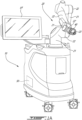
- a robotized computer-assisted surgery (CAS) system is generally shown at 10, and is used to provide surgery assistance to an operator.
- the robotized CAS system 10 may be robotized in a variant, and has, may have or may be used with a robot as shown by its one or more robot arms 20, a tracking device 30, a CAS controller 50, a tracking module 60, and a robot driver 70, or any combination thereof:
- interfaces I/F such as displays, screens, computer station, servers, and like etc. Secondary robotized CAS systems may also be used for redundancy.
- the interfaces I/F may include one such interface as part of the base or station supporting the robot arm 20, as shown in Fig. 1A .
- any of the links 22, including a wrist or like distal-most link 22' may optionally incorporate a force/torque sensor for collaborative/cooperative control mode, in which an operator manipulates the robot arm 20.
- the robot arm 20 is shown being a serial mechanism, arranged for the tool head 23 to be displaceable in a desired number of degrees of freedom (DOF).
- DOF degrees of freedom
- the robot arm 20 controls 6-DOF movements of the tool head, i.e., X, Y, Z in the coordinate system, and pitch, roll and yaw. Fewer or additional DOFs may be present.
- joints 21 and links 22 are powered for the robot arm 20 to move as controlled by the CAS controller 50 in the six DOFs, and in such a way that the position and orientation of the tool head 23 in the coordinate system may be known, for instance by readings from encoders on the various joints 21, or from any integrated rotational joint sensing enabling rotation of the joints 21 to be quantified, and/or via tracking by the tracking device 30.
- the tool head 23 may be calibrated relative to the robot arm 20, in such a way that the position and/or orientation of the tool head 23 in the referential system of surgery is known.
- the powering of the joints is such that the tool head 23 of the robot arm 20 may execute precise movements, such as moving along a single direction in one translation DOF, or being restricted to moving along a plane, among possibilities.
- Such robot arms 20 are known, for instance as described in United States Patent Application Serial no. 11/610,728 , and incorporated herein by reference.
- an inertial sensor unit may be on the robot arm 20 for the tracking of the end effector of the robot arm 10.
- the tool head 23 of robot arm 20 may be defined by a chuck or like tool interface, that is non-powered and that serves as a guide and/or support for tools T manipulated and/or supported by the operator (e.g., a surgeon, physician or like medical professional).
- powered tools such as a reamer (e.g., cylindrical, tapered), a reciprocating saw, a retractor, a laser rangefinder or light-emitting device (e.g., the indicator device of US Patent No. 8,882,777 ), laminar spreader depending on the nature of the surgery.
- the various tools may be part of a multi-mandible configuration or may be interchangeable, whether with human assistance, or as an automated process.
- the installation of a tool in the tool head may then require some calibration in order to track the installed tool in the X, Y, Z coordinate system of the robot arm 20.
- the tool head 23 of the robot arm 20 may also be a universal instrument adapter, which can be positioned by robot arm 20 relative to the surgical area in a desired orientation according to a surgical plan, such as a plan based on preoperative imaging.
- the universal instrument adapter may include a tool base, an extension arm, at the end of which a cutting guide is located.
- the cutting guide may be known as a cutting block, adapter block, etc.
- the extension arm may have a first segment and second segment, though fewer or more segments may be present, so as to give a given orientation to the cutting guide relative to the tool head.
- the cutting guide may have a body defining a guide surface (e.g., cut slot), and pin holes.
- the cutting guide can be configured as a talus resection block for use in a total knee arthroplasty. Other configurations of the cutting guide may be used, such as with or without pin holes. Again, calibration steps may be performed if required to calibrate any end effector instrument.
- the CAS controller 50 can manipulate the robot arm 20 automatically by the robot driver 70, or by a surgeon manually operating the robot arm 20 (e.g. physically manipulating, via a remote controller through the interface I/F) to move the end effector of the robot arm 20 to the desired location, e.g., a location called for by a surgical plan to align an instrument relative to the anatomy.
- a surgeon manually operates the robot arm 20 it may be in a collaborative mode in which the robot arm 20 may sense forces applied to the robot arm 20 and actuate its joints 21 as a function of force vectors. Once aligned, a step of a surgical procedure can be performed.
- the robot arm 20 may include sensors 25 in its various joints 21 and links 22.
- the sensors 25 may be of any appropriate type, such as rotary encoders, optical sensors, position switches, for the position and orientation of the end effector, and of the tool in the tool head 23 (e.g., cutting block) to be known.
- the tracking module 60 may determine the position and orientation of the robot arm 20 in a frame of reference of the robot arm 20, such as by obtaining the position (x,y,z) and orientation (phi, theta, ro) of the tool from the robot driver 70 using the sensors 25 in the robot arm 20.
- the robot arm 20 may be the coordinate measuring machine (CMM) of the robotized CAS system 10, with a frame of reference (e.g., coordinate system, referential system) of the procedure being relative to the fixed position of the base of the robot 20.
- CMM coordinate measuring machine
- the sensors 25 must provide the precision and accuracy appropriate for surgical procedures.
- the coupling of tools to the robot arm 20 may automatically cause a registration of the position and orientation of the tools in the frame of reference of the robot arm 20, though steps of calibration could be performed. For example, when a cutting guide is coupled to the robot arm 20, a position and orientation of the guide surface may be registered for its subsequent tracking as the robot arm 20 moves in space.
- the geometry of the cutting guide is thus known, as well as the manner by which the cutting guide is coupled to the robot arm 20, to allow this automatic registration. Additional steps may be performed to register/calibrate the cutting guide, such as the contact with a probe, image processing, data entry, etc.
- the sensors 25 may include force/torque sensors for three axis of torque and three directions of forces, for example. Such sensors may be useful as part of the operation of a collaborative mode.
- the electrical interface 40 is connected directly to the wrist 22' ( Fig. 7 ), and is between the wrist 22' or other distal face of the robotic arm 20, and the tool head 23 ( Fig. 3 ) or other proximal face of the end effector including the tool interface 23' ( Fig. 6 ) if present.
- the tool head 23 is shown as being a passive (i.e., non-powered) clamp 23A at the end of an arm 23B projecting from a base 23C, as an example among others.
- the electrical interface 40 may incorporate electrical insulation, to avoid any electrical interference with a tool supported by the tool head 23.
- the electrical interface 40 is powered to bring additional functionalities to the end of the distal end of the robot arm 20, as described below, including signaling capacity and data transmission. Accordingly, the electrical interface 40 may be layered internally, such as by having a shielding layer positioned distally relative to a printed-circuit board (PCB) or other circuitry embedded or located inside the electrical interface 40.
- the electrical interface 40 has any appropriate body shape.
- the electrical interface 40 is shown in Figs. 2 and 3 as optionally having a disc-shaped (disk-shaped) body 40A, with a round geometry, through other geometries are contemplated (e.g., polygonal, square, oval, etc), one of which is described below.
- a dimension of the disc body 40A is greater than that of a base of the tool head 23 or like proximal face of the end effector, so as to define a peripheral or like surrounding surface 40B that projects beyond the base 23C of the tool head 23.
- Surface 40B may lie in an axial plane. This could be achieved in other ways, such as by having a different geometry.
- the base 23C is generally of similar shape and size (e.g., diameter) as that of the wrist 22'.
- the disc body 40A may act as a flange, and may also serve as a support or interface for a drape. In a variant, a drape is connected to a rear surface of the disc body 40A.
- the electrical interface 40 may be powered via the robot arm 20, or by wires internally routed into the robot arm 20 or exterior to the robot arm 20.
- the wiring may be proximally located relative to the drape, if present.
- the electrical interface 40 may include a battery, so as to be wireless and battery operated.
- the electrical interface 40 may include a telecommunications unit, using any appropriate telecommunications protocol (e.g., wi-fi, Bluetooth ® , etc).
- the peripheral surface 40B may be said to be a distal surface, as it is located toward the distal end of the robot arm 20. Moreover, the peripheral surface 40B may be normal to a rotational axis of the wrist 20' as a possibility. Accordingly, the peripheral surface 40B faces distally, toward the tool head 23. In an embodiment, the peripheral surface 40B is substantially flat, though this is optional.
- the electrical interface 40 may have a mating connector 41 as part of a connection configuration.
- the mating connector 41 is shown as being a male connector, and/or may have cylindrical shape or any other projecting shape, but other configurations are possible, including a female connector.
- the mating connector 41 could have a clocking feature to ensure a unique complementary positioning of the tool head 23 on the electrical interface 40.
- Attachment bore(s) 42 such as threaded bores, may be circumferentially distributed around the mating connector 41 if present, or may be at other locations, and may also be part of the connector configuration.
- the attachment bore(s) 42 may be used to secure a tool such as the tool head 23 to the electrical interface 40. Accordingly, some compatibility is required between the mating connector 41 and/or attachment bore(s) 42, for tools to be attached to the electrical interface 40.
- different patterns and configurations of attachment bores 42 may be present as part of the connector configuration, for the electrical interface 40 to be compatible with different tool types.
- Alignment features 43 may optionally be present, for example if no other clocking feature is present, and may be part of the connector configuration.
- the alignment features 43 may be circumferentially distributed around the mating connector 41 if present, or may be at other locations.
- the alignment features 43 may be conical holes and/or conical projections, matingly engaged with complementary features on the tool head 23.
- the alignment features 43 are used to ensure a precise positioning engagement of the tool head 23, for example by removing any possible play between the tool head 23 and the electrical interface 40 once connected, provided the fastener(s) received in the attachment bore(s) 42 is suitably tightened, such as threaded members with knobs 23D on the tool head 23 ( Fig. 2 ).
- the alignment features 43 contribute to the stability of the assembly, and to the precision of the positioning of the tool head 23 in the referential system, as the geometrical relation between the tool head 23 and the electrical interface 40 is predictable and reproducible.
- the alignment features 43 may be factor in the improvement of surgical precision.
- Light source(s) 44 may be located on the peripheral surface 40B.
- the light sources 44 are embedded in the disc body 40A so as not to project beyond a surface of the peripheral surface 40B, but this is merely optional.
- their light is projected in a distal direction, generally along an axis of the wrist 22'.
- the wrist 22' is in the vicinity of the surgical site, and as the wrist 22' may often support a tool (e.g., tool head 23) that is along the rotation axis of the wrist 22', the light source(s) 44 is(are) strategically positioned to assist in providing light at the surgical site.
- the light source 44 there may be more than one light source 44, with some of the light sources 44 located in a lower half of the disc body 40A, and some of the light sources 44 located in an upper half of the disc body 40A.
- the location of the light sources 44 on the lower half and upper half may ensure that a zone that is otherwise shaded by the tool head 23 is illuminated (lights may be in all four quadrants if the peripheral surface 40B extends for more than 270 degrees.
- the light source(s) 44 is(are) light-emitted diodes, and may be selected based on light spectrum requirements. Other types of light sources could be used.
- the light source(s) 44 if present, enable the electrical interface 40 to provide focused lighting on the operated area.
- an emitter 45A and a receiver 45B may also be located on the peripheral surface 40B of the disc body 40A.
- the emitter 45A and the receiver 45B work as a pair to perform detection, such as ranging, proximity sensing, tracking.
- the emitter 45A and the receiver 45B are shown as a separate pair, but the emitter 45A and the receiver 45B may be grouped in a single location on the peripheral surface 40B, or multiple pairs may also be present.
- the technology used by the emitter 45A and receiver 45B may be of any type. For example, the technology can be based on a reflection of light, a laser, a sound or an ultrasound or other.
- the emitter 45A and receiver 45B are on the peripheral surface 40B, giving them a close-up point of view of the surgical site, aligned with the axis of the wrist 22'.
- FIG. 4-7 another embodiment of the electrical interface is illustrated as 40'.
- the electrical interface 40' shares some features with the electrical interface 40 of Figs. 2 and 3 , and like reference numerals will indicate like components.
- the electrical interface 40' is also connected directly to the wrist 22' ( Figs. 6 and 7 ), and is between the wrist 22' and the tool head 23 ( Fig. 6 ) or tool interface 43' if present, again the tool head 23 may be a passive (i.e., non-powered) clamp 23A, as an example among others.
- the electrical interface 40' may also incorporate electrical insulation, to avoid any electrical interference with a tool supported by the tool head 23.
- the electrical interface 40' is powered to bring additional functionalities to the end of the distal end of the robot arm 20, as described below, including data transmission, signaling.
- the electrical interface 40' may include a shielding layer positioned distally relative to a printed-circuit board (PCB) or other electric/electronic components.
- PCB printed-circuit board
- the electrical interface 40' has any appropriate body shape.
- the electrical interface 40' resembles the electrical interface 40 in that it is generally disc-shaped (disk-shaped) body 40A, but with truncated portions in the outer periphery 40C, defining optional flat support surfaces 40D in the outer periphery 40C. As observed, the support surfaces 40D may face downwardly.
- the body 40A may also have width dimensions greater than that of a base of the tool head 23, so as to define the peripheral surface 40B that projects beyond the base 23C of the tool head 23.
- the body 40A may thus be viewed as a flange relative to the wrist 22'.
- the body 40A may serve as a support or interface for a drape. In a variant, a drape is connected to a rear surface of the body 40A.
- the electrical interface 40' may be powered via the robot arm 20, or by wires internally routed into the robot arm 20 or exterior to the robot arm 20.
- the wiring may be proximally located relative to the drape, if present.
- the electrical interface 40' may include a battery, so as to be wireless and battery operated.
- the electrical interface 40 may include a telecommunications unit, using any appropriate telecommunications protocol (e.g., wi-fi, Bluetooth ® , etc).
- the peripheral surface 40B may be said to be a distal surface, as it is located toward the distal end of the robot arm 20. Moreover, the peripheral surface 40B may be normal to a rotational axis of the wrist 20' as a possibility. Accordingly, the peripheral surface 40B faces distally, toward the tool head 23. In an embodiment, the peripheral surface 40B is substantially flat, though this is optional.
- the electrical interface 40' may have a mating connector 41, as part of a connector configuration.
- the mating connector 41 is shown as being a male connector, or cylindrical shape, but other configurations are possible, including a female connector.
- the mating connector 41 could have a clocking feature to ensure a unique complementary positioning of the tool head 23 on the electrical interface 40'. This is visible in the various embodiments in the form of a keyway on the mating connector 41.
- Attachment bore(s) 42 may be circumferentially distributed around the mating connector 41 if present, or may be at other locations, and may be part of the connector configuration.
- the attachment bore(s) 42 may be used to secure a tool such as the tool head 23 to the electrical interface 40'. Some compatibility is required between the mating connector 41 and/or attachment bore(s) 42, for tools to be attached to the electrical interface 40'. Moreover, different patterns and configurations of attachment bores 42 may be present, for the electrical interface 40' to be compatible with different tool types.
- Alignment features 43 may optionally be present, as part of the connector configuration.
- the alignment features 43 may be circumferentially distributed around the mating connector 41 if present, or may be at other locations.
- the alignment features 43 may be in a non-symmetrical pattern, to create a unique orientation connection correspondence between the electrical interface 40' and the tool head 23 (or any other tool to be connected to the electrical interface 40'.
- the alignment features 43 may be conical holes and/or conical projections, matingly engaged with complementary features on the tool head 23.
- the alignment features 43 are used to ensure a precise positioning engagement of the tool head 23, for example by removing any possible play between the tool head 23 and the electrical interface 40' once connected, provided the fastener(s) received in the attachment bore(s) 42 is suitably tightened, such as threaded members with knobs 23D on the tool head 23 ( Fig. 6 ).
- the alignment features 43 contribute to the stability of the assembly, and to the precision of the positioning of the tool head 23 in the referential system, as the geometrical relation between the tool head 23 and the electrical interface 40' is predictable and reproducible.
- Light source(s) 44 may be located on the peripheral surface 40B.
- the light sources 44 are embedded in the disc body 40A so as not to project beyond a surface of the peripheral surface 40B, but this is merely optional.
- Other light sources 44' may be provided on the peripheral surface 40C and/or on the flat support surfaces 40D, and may be selectively turned on an off (such light sources 44' may also be in the electrical interface 40). These light sources 44' may be in every quadrant of the electrical interface 40. As the light sources 44 are on the peripheral surface 40B, their light is projected in a distal direction, generally along an axis of the wrist 22'.
- the light source 44 and 44' are strategically positioned to assist in providing light at the surgical site.
- there may be more than one light source 44 with some of the light sources 44 located in a lower half of the disc body 40A, and some of the light sources 44 located in an upper half of the disc body 40A.
- the location of the light sources 44 and 44' on the lower half and upper half may ensure that a zone that is otherwise shaded by the tool head 23 is illuminated.
- the light source 44 and/or 44' are light-emitted diodes, and may be selected based on light spectrum requirements. Other types of light sources could be used.
- the light sources 44 and 44' if present, enable the electrical interface 40 to provide focused lighting on the operated area.
- a vision system may be provided in the electrical interface 40', as shown by the presence of one or more lenses 46, located on the flat support surfaces 40C of the body 40A, but potentially located elsewhere, including on the peripheral surface 40B.
- the vision system may be used to capture images, video feed, and may also be used for other functions such ranging, proximity sensing, tracking.
- the lenses 46 are shown as a pair, so as to enable triangulation tracking, depth camera functionality, such as in the infrared spectrum.
- Buttons 47 may be provided on the electrical interface 40' (and also in the electrical interface 40 though not shown).
- the buttons 47 may be mechanical and thus connected to switches within the electrical interface 40'. Other technologies can be used, include capacitive sensing.
- the buttons 47 may strategically be positioned on the periphery 40C of the body 40A, so as to be readily accessible.
- the buttons 47 may be configured by a user of the robot arm 20 to perform selected functions, such as some functions related to the operation of the electrical interface 40' (e.g., turning lights 44 on/off), or optionally functions associated with the surgical workflow, in a manner similar to a keyboard, mouse, etc.
- the buttons 47 may be taught some functions.
- the electrical interface 40' may use the vision system to perform various functions.
- the electrical interface 40' may be used to facilitate patient landmark registration, by capturing images of such bone landmarks in proximity to the patient.
- the captured images of the vision system of the electrical interface 40' may be used to monitor the relative position of the patient in relation to the instrumentation in real time throughout the surgery, from a privileged proximal point of view, which may result in enhanced accuracy.
- Both electrical interfaces 40 and 40' are configured to be placed in between a link of the robotic arm 20, such as the wrist 22', and the end effector (including any passive or active component, tool) that is at the distal end of the robotic arm 20. Accordingly, the electrical interfaces 40 and 40' may be retrofitted to existing systems, and their connector configurations may be disposed depending on the type of robotic arm 20/end effector. Moreover, their thinness gives the electric interfaces 40 and 40' a small footprint, for example in comparison to other interfaces and tracking camera.
- the tracking device 30 may optionally be used to track the patient tissue, instruments, and the robot arm 20.
- the tracking device 30 may include the vision system that is on the electrical interface 40'.
- the tracking device 30 includes a Navitrack ® system having the capacity to track retroreflective elements of tracker devices on the various objects (e.g., bones, tools, implants).
- the tracking device 30 may have the capacity to capture images, e.g., in video format, using camera technology similar such as depth cameras, with optional pattern projector, as described below, or may be a different imaging technology, to provide its video feed.
- the tracking device 30 includes multiple separate image capture devices from different points of view, including the lens(es) 46 of the vision system of the electrical interface 40'.
- the tracking device 30 may include or may be embodied by a head-mounted device worn by an operator, such as by the surgeon performing surgery. If present, the head-mounted device may have a display screen to provide data to the wearer, though this may be optional in an embodiment.
- the tracking device 30 may produce structured light illumination for tracking objects with structured light 3D imaging.
- structured light illumination a portion of the objects is illuminated with one or multiple patterns from a pattern projector or like light source.
- Structured light 3D imaging is based on the fact that a projection of a line of light from the pattern projector onto a 3D shaped surface produces a line of illumination that appears distorted as viewed from perspectives other than that of the pattern projector. Accordingly, imaging such a distorted line of illumination allows a geometric reconstruction of the 3D shaped surface.
- Imaging of the distorted line of illumination is generally performed using one or more cameras (including appropriate components such as e.g., lens(es), aperture, image sensor such as CCD, image processor) which are spaced apart from the pattern projector so as to provide such different perspectives, e.g., triangulation perspective.
- the pattern projector is configured to project a structured light grid pattern including many lines at once as this allows the simultaneous acquisition of a multitude of samples on an increased area. In these embodiments, it may be convenient to use a pattern of parallel lines. However, other variants of structured light projection can be used in some other embodiments.
- the structured light grid pattern can be projected onto the surface(s) to track using the pattern projector.
- the structured light grid pattern can be produced by incoherent light projection, e.g., using a digital video projector, wherein the patterns are typically generated by propagating light through a digital light modulator.
- digital light projection technologies include transmissive liquid crystal, reflective liquid crystal on silicon (LCOS) and digital light processing (DLP) modulators.
- the resolution of the structured light grid pattern can be limited by the size of the emitting pixels of the digital projector.
- patterns generated by such digital display projectors may have small discontinuities due to the pixel boundaries in the projector. However, these discontinuities are generally sufficiently small that they are insignificant in the presence of a slight defocus.
- the structured light grid pattern can be produced by laser interference.
- two or more laser beams can be interfered with one another to produce the structured light grid pattern wherein different pattern sizes can be obtained by changing the relative angle between the laser beams.
- the tracking device 30 may consequently include the cameras to acquire backscatter images of the illuminated portion of objects.
- the cameras capture the pattern projected onto the portions of the object.
- the cameras are adapted to detect radiations in a region of the electromagnetic spectrum that corresponds to that of the patterns generated by the light projector.
- the known light pattern characteristics and known orientation of the pattern projector relative to the cameras are used by the tracking module 60 to generate a 3D geometry of the illuminated portions, using the backscatter images captured by the camera(s).
- a single camera spaced form the pattern projector can be used, using more than one camera may increase the field of view and increase surface coverage, or precision via triangulation.
- the tracking device 30 may also have one or more filters integrated into either or both of the cameras to filter out predetermined regions or spectral bands of the electromagnetic spectrum.
- the filter can be removably or fixedly mounted in front of any given camera.
- the filter can be slidably movable into and out of the optical path of the cameras, manually or in an automated fashion.
- multiple filters may be periodically positioned in front of a given camera in order to acquire spectrally resolved images with different spectral ranges at different moments in time, thereby providing time dependent spectral multiplexing.
- Such an embodiment may be achieved, for example, by positioning the multiple filters in a filter wheel that is controllably rotated to bring each filter in the filter wheel into the optical path of the given one of the camera in a sequential manner.
- the filter can be used to provide a maximum contrast between different materials which can improve the imaging process and more specifically the soft tissue identification process.
- the filter can be used to filter out bands that are common to backscattered radiation from typical soft tissue items, the surgical structure of interest, and the surgical tool(s) such that backscattered radiation of high contrast between soft tissue items, surgical structure and surgical tools can be acquired.
- the filter can includes band pass filters configured to let pass only some spectral bands of interest.
- the filter can be configured to let pass spectral bands associated with backscattering or reflection caused by the bones, the soft tissue while filtering out spectral bands associated with specifically colored items such as tools, gloves and the like within the surgical field of view.
- Other methods for achieving spectrally selective detection including employing spectrally narrow emitters, spectrally filtering a broadband emitter, and/or spectrally filtering a broadband imaging detector, can also be used.
- the CAS controller 50 is shown in greater detail relative to the other components of the robotized CAS system 10.
- the CAS controller 50 has a processor unit 51 (one or more processors) and a non-transitory computer-readable memory 52 communicatively coupled to the processing unit 51 and configured for executing computer-readable program instructions executable by the processing unit 51 to perform some functions, such as tracking the patient tissue and tools, using the camera feed from the tracking device 30.
- the CAS controller 50 may also control the movement of the robot arm 20.
- the robotized CAS system 10 may comprise various types of interfaces I/F, for the information to be provided to the operator.
- the interfaces I/F may include a monitor and/or screens including wireless portable devices (e.g., phones, tablets), audio guidance, LED displays, among many other possibilities.
- the interface D includes a graphic-user interface (GUI) operated by the system 10.
- the CAS controller 50 may drive the robot arm 20 in performing the surgical procedure based on the surgery planning achieved preoperatively.
- the CAS controller 50 may run various modules, in the form of algorithms, code, non-transient executable instructions, etc, in order to operate the CAS system 10 in the manner described herein.
- the CAS controller 50 may be part of any suitable processor unit(s), such as a personal computer or computers including laptops and desktops, tablets, server, cloud, etc.
- the tracking module 60 may be a subpart of the CAS controller 50, or an independent module or system.
- the tracking module 60 receives from the tracking device 30 (if present) the video feed of the surgical scene, e.g., as backscatter images of the objects.
- the video images and the orientation data are synchronized, as they are obtained and processed simultaneously. Other processing may be performed to ensure that the video footage and the orientation data are synchronized.
- the tracking module 60 processes the video images to track one or more objects, such as a bone, an instrument, etc.
- the tracking module 60 may determine the relative position of the objects, and segment the objects within the video images.
- the tracking module 60 may process the video images to track a given portion of an object, that may be referred to as a landmark.
- the tracking module 60 may also be provided with models of the objects to be tracked.
- the tracking module 60 may track bones and tools, and hence uses virtual bone models and tool models.
- the bone models may be acquired from pre-operative imaging (e.g., MRI, CT-scans), for example in 3D or in multiple 2D views, including with 2D X-ray to 3D bone model technologies.
- the virtual bone models may also include some image processing done preoperatively, for example to remove soft tissue or refine the surfaces that will be exposed and tracked.
- the virtual bone models may be of greater resolution at the parts of the bone that will be tracked during surgery, such as the knee articulation in knee surgery.
- the bone models may also carry additional orientation data, such as various axes (e.g., longitudinal axis, mechanical axis, etc).
- the bone models may therefore be patient specific. It is also considered to obtain bone models from a bone model library, with the data obtained from the video images used to match a generated 3D surface of the bone with a bone from the bone atlas.
- the virtual tool models may be provided by the tool manufacturer, or may also be generated in any appropriate way so as to be a virtual 3D representation of the tool(s).
- the tracking module 60 may generate 3D models using the video images. For example, if the tracking module 60 can have video images of a tool, from 360 degrees, it may generate a 3D model that can be used for subsequent tracking. This intraoperative model may or may not be matched with pre-existing or pre-operative model of the tool.
- Additional data may also be available, such as tool orientation (e.g., axis data and geometry).
- tool orientation e.g., axis data and geometry
- the tracking module 60 may recognize an object in the image processing and/or may obtain additional information, such as the axes related to bones or tools.
- the image processing by the tracking module 60 may be assisted by the presence of the models, as the tracking module 60 may match objects from the video images with the virtual models.
- the electrical interface 40 and 40' may be generally described as being an interface for a robotic arm that may have a body having a first axial face adapted to be connected to a distal face of a link of a robotic arm, a second axial face adapted to be connected to a proximal face of an end effector, the second axial face having a geometry differing from a geometry of the proximal face of the end effector so as to define a peripheral band in the second axial face, the peripheral band facing distally; a connection configuration for the interface to be fixed to the link and for the end effector to be fixed to the interface; circuitry embedded in the body; and at least one light source in the peripheral band, the at least one light source connected to the circuitry to produce light in a distal direction of the robotic arm.
- the electrical interface 40 and 40' may alternatively be described as An interface for a robotic arm having a body having a first axial face adapted to be connected to a distal face of a link of a robotic arm, a second axial face adapted to be connected to a proximal face of an end effector; a connection configuration for the interface to be fixed to the link and for the end effector to be fixed to the interface; circuitry embedded in the body; a circumferential surface defined between the first axial face and the second axial face; and at least one light source in the circumferential surface, the at least one light source connected to the circuitry to produce light.
Landscapes
- Health & Medical Sciences (AREA)
- Surgery (AREA)
- Life Sciences & Earth Sciences (AREA)
- Engineering & Computer Science (AREA)
- Heart & Thoracic Surgery (AREA)
- Biomedical Technology (AREA)
- Nuclear Medicine, Radiotherapy & Molecular Imaging (AREA)
- Medical Informatics (AREA)
- Molecular Biology (AREA)
- Animal Behavior & Ethology (AREA)
- General Health & Medical Sciences (AREA)
- Public Health (AREA)
- Veterinary Medicine (AREA)
- Robotics (AREA)
- Pathology (AREA)
- Oral & Maxillofacial Surgery (AREA)
- Manipulator (AREA)
Applications Claiming Priority (1)
| Application Number | Priority Date | Filing Date | Title |
|---|---|---|---|
| US202363498665P | 2023-04-27 | 2023-04-27 |
Publications (2)
| Publication Number | Publication Date |
|---|---|
| EP4454590A2 true EP4454590A2 (fr) | 2024-10-30 |
| EP4454590A3 EP4454590A3 (fr) | 2024-12-18 |
Family
ID=90922430
Family Applications (1)
| Application Number | Title | Priority Date | Filing Date |
|---|---|---|---|
| EP24172789.0A Pending EP4454590A3 (fr) | 2023-04-27 | 2024-04-26 | Interface électrique pour bras de robot chirurgical |
Country Status (2)
| Country | Link |
|---|---|
| US (1) | US20240358453A1 (fr) |
| EP (1) | EP4454590A3 (fr) |
Citations (1)
| Publication number | Priority date | Publication date | Assignee | Title |
|---|---|---|---|---|
| US8882777B2 (en) | 2006-03-17 | 2014-11-11 | Zimmer Technology, Inc. | Indicator device for use with a surgical guide instrument |
Family Cites Families (13)
| Publication number | Priority date | Publication date | Assignee | Title |
|---|---|---|---|---|
| WO2012088471A1 (fr) * | 2010-12-22 | 2012-06-28 | Veebot, Llc | Systèmes et procédés d'introduction autonome d'une aiguille intraveineuse |
| DE102014117408A1 (de) * | 2014-11-27 | 2016-06-02 | avateramedical GmBH | Vorrichtung zur robotergestützten Chirurgie |
| AU2016225968B2 (en) * | 2015-03-05 | 2020-07-23 | Think Surgical, Inc. | Methods for locating and tracking a tool axis |
| US11678939B2 (en) * | 2017-10-05 | 2023-06-20 | Mobius Imaging Llc | Methods and systems for performing computer assisted surgery |
| DE102017009319C5 (de) * | 2017-10-09 | 2023-08-03 | Günther Zimmer | Adaptersystem zur Anbindung des letzten Gliedes einer kinematischen Kette an eine Handhabungsvorrichtung |
| DK201800225A1 (da) * | 2018-05-19 | 2019-12-16 | Life Science Robotics Aps | Robot for anvendelse ved genoptræning af ekstremiteter. |
| US11864857B2 (en) * | 2019-09-27 | 2024-01-09 | Globus Medical, Inc. | Surgical robot with passive end effector |
| EP3821843A1 (fr) * | 2019-11-12 | 2021-05-19 | Surgivisio | Système chirurgical robotique |
| CN113081269B (zh) * | 2020-01-08 | 2024-07-23 | 格罗伯斯医疗有限公司 | 用于对患者的解剖特征进行手术的手术机器人系统 |
| WO2022150802A1 (fr) * | 2021-01-08 | 2022-07-14 | Xyz Robotics Inc. | Outils de préhension souples pour des systèmes robotiques de type preneur-placeur |
| US12343105B2 (en) * | 2021-02-11 | 2025-07-01 | Cilag Gmbh International | Robotic surgical instruments with rotary shaft power transmission |
| US12260561B2 (en) * | 2021-06-15 | 2025-03-25 | Orthosoft Ulc | Tracking system for robotized computer-assisted surgery |
| EP4389050A1 (fr) * | 2022-12-22 | 2024-06-26 | Ecential Robotics | Ensemble de suivi et système robotique |
-
2024
- 2024-04-26 EP EP24172789.0A patent/EP4454590A3/fr active Pending
- 2024-04-26 US US18/646,976 patent/US20240358453A1/en active Pending
Patent Citations (1)
| Publication number | Priority date | Publication date | Assignee | Title |
|---|---|---|---|---|
| US8882777B2 (en) | 2006-03-17 | 2014-11-11 | Zimmer Technology, Inc. | Indicator device for use with a surgical guide instrument |
Also Published As
| Publication number | Publication date |
|---|---|
| US20240358453A1 (en) | 2024-10-31 |
| EP4454590A3 (fr) | 2024-12-18 |
Similar Documents
| Publication | Publication Date | Title |
|---|---|---|
| US12201383B2 (en) | Bone and tool tracking in robotized computer-assisted surgery | |
| US20250009441A1 (en) | Systems And Methods For Surgical Navigation | |
| US12238433B2 (en) | Systems and methods for tracking objects | |
| US12544152B2 (en) | Systems and methods for visibly communicating a condition to a tracker using remote illumination | |
| JP2017000771A (ja) | 位置調整デバイス並びにロボット支援手術のための装置及び方法 | |
| US20230346484A1 (en) | Robotic surgery system with user interfacing | |
| JP2021194538A (ja) | 基準シードを介した可視光での外科手術での対象の追跡および合成画像登録 | |
| US20240358454A1 (en) | Surgical robotic arm with proximity skin sensing | |
| US20230126611A1 (en) | Information processing apparatus, information processing system, and information processing method | |
| KR20220024055A (ko) | 추적 시스템 시야 위치설정 시스템 및 방법 | |
| EP4454590A2 (fr) | Interface électrique pour bras de robot chirurgical | |
| US20240197409A1 (en) | Tool navigation in mixed reality computer-assisted surgery | |
| US20250032133A1 (en) | Computer-assisted navigation of lock hole in implant | |
| US20250134606A1 (en) | Robotic surgery system with user interfacing | |
| US20250391551A1 (en) | System and method for managing surgical hardware | |
| US20250186144A1 (en) | Device and method for tracking movement of robot in robot-assisted surgery | |
| WO2025189285A1 (fr) | Traqueur chirurgical mobile | |
| WO2025222291A1 (fr) | Planification avancée pour évaluation d'accessibilité en chirurgie assistée par robot | |
| WO2026042070A1 (fr) | Suivi anatomique par projection de motif actif | |
| CN121512704A (zh) | 用于全髋关节成形术(tha)规程的端部执行器 |
Legal Events
| Date | Code | Title | Description |
|---|---|---|---|
| PUAI | Public reference made under article 153(3) epc to a published international application that has entered the european phase |
Free format text: ORIGINAL CODE: 0009012 |
|
| STAA | Information on the status of an ep patent application or granted ep patent |
Free format text: STATUS: REQUEST FOR EXAMINATION WAS MADE |
|
| 17P | Request for examination filed |
Effective date: 20240426 |
|
| AK | Designated contracting states |
Kind code of ref document: A2 Designated state(s): AL AT BE BG CH CY CZ DE DK EE ES FI FR GB GR HR HU IE IS IT LI LT LU LV MC ME MK MT NL NO PL PT RO RS SE SI SK SM TR |
|
| PUAL | Search report despatched |
Free format text: ORIGINAL CODE: 0009013 |
|
| AK | Designated contracting states |
Kind code of ref document: A3 Designated state(s): AL AT BE BG CH CY CZ DE DK EE ES FI FR GB GR HR HU IE IS IT LI LT LU LV MC ME MK MT NL NO PL PT RO RS SE SI SK SM TR |
|
| RIC1 | Information provided on ipc code assigned before grant |
Ipc: A61B 17/00 20060101ALN20241113BHEP Ipc: A61B 90/00 20160101ALN20241113BHEP Ipc: A61B 34/20 20160101ALN20241113BHEP Ipc: A61B 34/30 20160101AFI20241113BHEP |