EP4454604A1 - Unité d'insertion pour appareil électrique de soins personnels - Google Patents
Unité d'insertion pour appareil électrique de soins personnels Download PDFInfo
- Publication number
- EP4454604A1 EP4454604A1 EP23170573.2A EP23170573A EP4454604A1 EP 4454604 A1 EP4454604 A1 EP 4454604A1 EP 23170573 A EP23170573 A EP 23170573A EP 4454604 A1 EP4454604 A1 EP 4454604A1
- Authority
- EP
- European Patent Office
- Prior art keywords
- charging device
- unit
- plug
- carrier
- housing
- Prior art date
- Legal status (The legal status is an assumption and is not a legal conclusion. Google has not performed a legal analysis and makes no representation as to the accuracy of the status listed.)
- Pending
Links
Images






Classifications
-
- A—HUMAN NECESSITIES
- A61—MEDICAL OR VETERINARY SCIENCE; HYGIENE
- A61C—DENTISTRY; APPARATUS OR METHODS FOR ORAL OR DENTAL HYGIENE
- A61C17/00—Devices for cleaning, polishing, rinsing or drying teeth, teeth cavities or prostheses; Saliva removers; Dental appliances for receiving spittle
- A61C17/16—Power-driven cleaning or polishing devices
- A61C17/22—Power-driven cleaning or polishing devices with brushes, cushions, cups, or the like
- A61C17/224—Electrical recharging arrangements
-
- A—HUMAN NECESSITIES
- A61—MEDICAL OR VETERINARY SCIENCE; HYGIENE
- A61C—DENTISTRY; APPARATUS OR METHODS FOR ORAL OR DENTAL HYGIENE
- A61C17/00—Devices for cleaning, polishing, rinsing or drying teeth, teeth cavities or prostheses; Saliva removers; Dental appliances for receiving spittle
- A61C17/16—Power-driven cleaning or polishing devices
- A61C17/22—Power-driven cleaning or polishing devices with brushes, cushions, cups, or the like
- A61C17/225—Handles or details thereof
-
- H—ELECTRICITY
- H02—GENERATION; CONVERSION OR DISTRIBUTION OF ELECTRIC POWER
- H02J—ELECTRIC POWER NETWORKS; CIRCUIT ARRANGEMENTS OR SYSTEMS FOR SUPPLYING OR DISTRIBUTING ELECTRIC POWER; SYSTEMS FOR STORING ELECTRIC ENERGY
- H02J50/00—Circuit arrangements or systems for wireless supply or distribution of electric power
- H02J50/10—Circuit arrangements or systems for wireless supply or distribution of electric power using inductive coupling
Definitions
- the invention relates to an insert unit for a handpiece of an electric personal care device, in particular an electric toothbrush, as well as a corresponding handpiece and a corresponding personal care device, in particular an electric toothbrush.
- the product structure of electric personal care devices in particular electric toothbrushes, nowadays comprises in particular a housing, a plug-in unit (which consists of several components, one or more of these components being able to at least partially penetrate the housing), a closure cover and a brush attachment.
- the assembly generally includes the manufacture of the housing, the assembly and provision of the plug-in unit and the manufacture of the closure cover, whereby the plug-in unit is inserted into the housing and the closure cover is attached to the housing, thereby closing the interior of the housing.
- the charging socket In systems with direct charging (charging via a physical electrical connection), the charging socket is regularly located in the device and the housing is closed with a cover to prevent water from entering the housing.
- the cover In addition to closing the inside of the housing, the cover is also used to physically close the circuit; the plug-in unit is therefore not functional on its own.
- the plug-in unit or its individual components are mounted on a frame unit (monoframe), which consists of two half-shell-like halves. First, the individual components are inserted into the first half-shell-like half and fixed with the second half-shell-like half. The frame unit is then pushed into the housing. The housing cover is then screwed onto the housing and locked or fixed there.
- a frame unit monoframe
- the present invention is therefore based on the object of providing an electric toothbrush in which the number of components can be reduced
- a further object of the invention is to provide an electric toothbrush with simple charging handling.
- the essence of the invention consists of the following: a plug-in unit for a handpiece of an electric personal care device, in particular an electric toothbrush, which has a plug-in carrier on which a drive unit, an on/off switch, a power source, a printed circuit board and a charging device are arranged.
- the plug-in unit is configured in such a way that a closed circuit can be produced with it alone and it is therefore able to function on its own.
- the plug-in carrier comprises a charging device carrier in the area of the charging device and the charging device carrier and/or the charging device form part of the outer surface of the handpiece when assembled.
- insert carrier in the present case includes such structures, in particular frame-like holding structures, on which the individual components of the insert unit can be arranged with sufficiently firm hold in order to ensure trouble-free insertion into the housing and later safe use of the device.
- the term "drive unit” here includes all suitable motors, in particular electric motors, such as direct current or AC motors.
- the drive types for the device are in particular vibrating drives (e.g. motor with eccentric for a vibrating movement with a standard head on the brush attachment), pivoting-oscillating drives (e.g. left-right pivoting movement with a standard head on the brush attachment) and oscillating-rotating drives (e.g. left-right rotating movement with a round head on the brush attachment).
- the movement involves a vibration generated by a motor with a connected eccentric.
- the motor speed ranges between 8,000 rpm and 15,000 rpm.
- the movement of the drive shaft (from its basic position) covers an angular range of +/- 1° to +/- 15°, preferably +/- 3° to +/- 10°.
- the motor speed in the unloaded state is from 7,000 rpm to 12,000 rpm, preferably from 9,000 rpm to 11,000 rpm. This results in 15,000 to 25,000 movements per minute.
- the movement of the drive shaft covers an angular range of +/- 10° to +/- 40°, preferably from +/- 20° to +/- 30° and most preferably from +/- 25°.
- the movement of the brush head from the basic position i.e. the angle of rotation of the bristle carrier, is +/- 15° to +/- 40°, preferably +/- 20° to +/- 30° when unloaded.
- the motor speed when unloaded is 3,500 rpm to 10,000 rpm, preferably 4,000 rpm to 7,000 rpm. This results in 7,000 to 10,000 movements per minute.
- the bristle field is aligned differently to the drive shaft/rotation axis depending on the drive.
- the bristle field is almost perpendicular to the drive shaft and the bristles are aligned parallel to the axis of rotation of the bristle holder.
- the bristle field is aligned perpendicular to the drive shaft, which corresponds to the axis of rotation.
- printed board refers in particular to structures such as printed circuit boards, circuit cards, circuit boards and printed circuits.
- the printed circuit board is connected in particular to the charging device, the energy source, the drive unit and the on/off switch. All electrical connections in the device are connected to the printed circuit board.
- the connections can be made using electrical lines/cables or plug or contact connections; for example, in the case of the on/off switch, via a mechanical or electrical coupling.
- on/off switch in this case includes both (particularly single-pole) mechanical and electronic pressure switches.
- energy source in this context includes in particular all suitable accumulators (rechargeable batteries) or batteries (disposable or reusable batteries).
- the "part of the outer surface of the handpiece” refers in particular to the rear part of the surface of the handpiece, which includes the charging device.
- the outer surface can in particular include essentially horizontal (i.e. essentially parallel to the longitudinal axis of the handpiece) or essentially vertical (i.e. essentially perpendicular to the longitudinal axis of the handpiece) areas, but also outwardly curved areas.
- the charging device carrier and/or the charging device are in any case partially open to the outside.
- charging device is understood here to mean a device for directly charging the corresponding device, i.e. basically without the need for an inductive charging station, for example.
- the charging device therefore comprises charging sockets, via which charging is carried out using a power supply unit that has a plug that corresponds to the charging socket.
- the design of the charging device as an inductive device is also conceivable in principle.
- charging device carrier in this case includes structures that ensure that the charging device is securely held on the plug-in unit and that at least partially enclose and/or at least partially support the charging device.
- the charging device carrier is also usually structurally configured to provide a seal between the plug-in unit and the housing.
- the charging device is open to the outside.
- the charging device comprises a plug-in device, in particular a charging socket for a corresponding plug of a power supply unit.
- a plug-in device in particular a charging socket for a corresponding plug of a power supply unit.
- This form of direct charging has proven to be particularly efficient in practice.
- the charging device comprises an inductive device, in particular a charging coil, for example for introducing a corresponding ferrite core.
- the charging device carrier preferably comprises a charging device carrier body and an end part.
- the charging device carrier body usually encloses the charging device, at least partially, with the charging device being open to the outside, and clamps it in (in the assembled state) to ensure a secure hold.
- the end part is usually the section of the charging device carrier which forms part of the outer surface of the corresponding device or forms the end of the surface to the outside, i.e. in particular in the rear area of the device or handset, where the charging device is also located.
- the end part can fulfill a protective function for the charging device as well as a handling function by being designed for the corresponding device to be set up vertically. In this way, the usual closure cover can be dispensed with.
- the loading device carrier is designed in one piece. This is particularly efficient in terms of production.
- a multi-part design of the loading device carrier is also provided, wherein the loading device carrier comprises a separate end part which can be locked to the loading device carrier body.
- the insertion unit forms a unit and is used as a whole, ie with the End piece inserted into the housing interior of the handset of the corresponding device.
- the charging device carrier can comprise a separate end part which can be (straight) plugged onto the charging device carrier body, i.e. essentially in a form-fitting manner with a snap-in or clamp fit if necessary.
- the plug-in unit can in turn be inserted as a whole, i.e. with the end part plugged onto the charging device carrier body, into the housing interior of the handset of the corresponding device.
- the multi-part structure allows different end parts to be installed, i.e. different sized base areas or specific, different designs.
- the charging device preferably comprises a, preferably hook-shaped, locking geometry, which is configured to cause the charging device to lock relative to the charging device carrier body when mounted. Furthermore, the charging device is preferably pressed into the charging device carrier body, whereby a positive connection occurs, which causes the charging device to be sealed relative to the charging device carrier body.
- the inner surface of the charging device carrier body is preferably designed to correspond and thus supports the pressing and sealing (e.g. by tapering in the insertion direction). This serves to protect the interior of the housing and the charging device itself.
- the charging device carrier body has a first sealing zone relative to a housing of a handset, preferably in the form of a first groove for receiving a first sealing element (e.g. an O-ring), which is configured to seal the insertion unit relative to the housing wall of the handset when mounted.
- a first sealing element e.g. an O-ring
- the charging device carrier body has a second sealing zone opposite a housing of a handpiece, preferably in the form of a second groove for receiving a second sealing element (e.g. an O-ring), which is configured to seal the plug-in unit in the assembled state. against the housing wall of the handset.
- This second sealing element is arranged in front of the first sealing element when viewed in the insertion direction of the insertion unit and provides additional sealing if necessary. In principle, however, it is also conceivable to use only the second (inner) sealing element.
- the charging device carrier body has a sealing zone opposite the end part, preferably in the form of a groove for receiving a sealing element (e.g. an O-ring), which is configured to effect an axial seal of the charging device carrier body against the end part when assembled.
- a sealing element e.g. an O-ring
- the end part also has a sealing zone opposite the housing of a hand part, preferably in the form of a groove for receiving a sealing element (e.g. an O-ring), which is configured to effect a lateral seal of the plug-in unit against the housing wall of the hand part when assembled.
- This double seal enables optimal protection to be achieved for this variant of the multi-part design of the charging device carrier.
- sealing elements can also be realized as molded elements made of soft components, so that assembly of the sealing element is not necessary, since the element is already molded in the injection molding process.
- the charging device and/or the charging device carrier body form a part of the outer surface of the handset, which extends substantially perpendicular to the longitudinal axis of the handset. This creates an effective base for vertically setting up the device and ensures open accessibility of the charging device.
- the end part of the charging device carrier forms part of the outer surface of the handpiece.
- the end part can form a substantially ring-shaped protective element for the charging device (in particular the charging socket pin), which at the same time forms an insertion opening for approximately a plug of a corresponding power supply unit.
- the design is preferably such that the device can be safely placed vertically.
- one or more locking lugs are arranged on the charging device carrier body, which are configured to engage in corresponding locking recesses in the housing wall of the handset when mounted. In this way, a robust anchoring of the plug-in unit to the housing is achieved.
- the locking lugs preferably have a wedge-like shape with an insertion bevel, a horizontally running part and a rear wall that ends essentially vertically. This design has proven to be particularly effective because the locking lugs rest with the rear wall at the back (i.e. against the insertion direction) on the corresponding walls of the locking recesses in the housing wall.
- the loading device carrier is spring-mounted on a support structure (the insertion unit) by means of a spring bearing.
- the spring bearing comprises a first spring clip and a second spring clip, which are preferably arranged independently of one another between the loading device carrier and the support structure. In this way, a particularly effective length compensation function can be provided (according to this embodiment, the loading device carrier presses against the end part and thus the insertion unit into the housing).
- Preferred components without a drive which can be implemented on the plug-in unit and are installed in or on the device, include motion detectors such as gyroscopes or motion sensors and lighting devices such as infrared lamps. Accordingly, a product without a drive can also be implemented with other electrical components using a corresponding plug-in unit.
- a further aspect of the invention comprises a handset for an electric personal care appliance, in particular for an electric toothbrush, which has a housing and a plug-in unit according to the above specifications.
- Yet another aspect of the present invention includes an electric personal care appliance, in particular an electric toothbrush, which has a handle according to the above specifications.
- the housing of the handset generally serves to position and guide the plug-in unit, which is at least partially determined by the shape of the plug-in carrier and/or the entire (i.e. equipped) plug-in unit and the space layout within the housing. Separate guides or positioning elements are not necessarily required; rather, this can be determined solely by the geometric design of the plug-in carrier and/or the equipped plug-in unit itself.
- any positioning or guide elements provided to ensure the transmission of force between the housing and the plug-in unit must ensure that the plug-in unit cannot rotate in the housing and that, at the same time, the plug-in unit is clearly positioned.
- the preferred elements here are locking recesses in the housing or the inner housing wall, which are made in the hard component or the hard plastic shell and may also be provided with a soft component.
- the positioning in the circumferential direction is such that the locking recesses can be arranged regularly or irregularly along the circumference, but a symmetrical arrangement is preferred (ie top versus bottom or front versus back).
- the locking recesses are preferably arranged at the front (towards the top) and at the back (towards the back); the angle between the recesses measured from the longitudinal axis or base line is between 20° and 90°, preferably between 30° and 60°.
- the dimensions of the locking recesses in the housing are in terms of length in the direction of the longitudinal axis from 0.3 mm to 3 mm, preferably from 0.5 mm to 2 mm.
- the width measured in the transverse direction is from 1 mm to 5 mm, preferably from 1.5 mm to 4 mm.
- the hole or the locking recess is preferably not open from the outside and is generally implemented in the hard component or hard plastic shell of the housing, for example as a blind hole. If implemented as a through hole in the hard component, the soft component can close part of the through hole, and the soft component can be arranged in such a way that it is later partially displaced by the locking lug.
- the depth in the finished housing is from 0.2 mm to 2 mm, preferably from 0.3 mm to 1 mm.
- the number of recesses is from 2 to 8, preferably from 3 to 4.
- the locking recesses preferably have a symmetrical structure (i.e. in relation to the longitudinal axis or a plane containing the longitudinal axis) or a regular structure (i.e. in relation to the cross-sectional plane and the division into the angles).
- the basic rule for the shape of the locking recesses is that during manufacture, it must be taken into account that appropriate demolding is possible.
- the outline of the locking recesses is usually rectangular, preferably oblong (i.e. they have a rounded, almost rectangular shape).
- the locking recesses are preferably shaped in such a way that a straight wall is perpendicular to the longitudinal axis of the handle or the housing. When assembled, this serves to interact with the associated locking lug.
- the shape is preferably a straight cylinder or a cylindrical shape on a rectangular or oblong base.
- a conical or truncated cone shape is also conceivable.
- the insert unit is inserted into the housing of the handset, with positioning and stop preferably being implemented in one. Twisting of the insert unit is prevented by the geometry or cross-sectional shape of the insert. In other words, a clear positioning is specified, with the shape in the front part of the insert unit in particular determining the alignment.
- the plug-in unit rests against the housing in various areas.
- Longitudinal guides are implemented, which define the alignment of the plug-in unit with protruding elements.
- the end position is only reached when it is inserted correctly, with the (vibration) motor at the front of the housing.
- the motor and the housing are at a preferably acute angle to the longitudinal axis, with the stop being implemented flatly in the housing at an angle to the longitudinal axis.
- the locking lugs When inserted correctly, the locking lugs engage in the corresponding locking recesses when the stop is reached, i.e. the locking lugs rest against the front of the housing and engage (preferably at the back) in the locking recesses on the housing.
- the insertion unit and its individual components are preferably secured by means of a clamping mechanism between the catch and the stop. In between, the insertion unit and the individual components are largely free, i.e. they only rest on the housing at certain points.
- the force is transmitted via the geometry of the insert.
- the detents are free on the sides, i.e. the locking lugs preferably do not lie on the sides of the locking recesses.
- the insert unit is preferably held in place by clamping it between the end part and the housing.
- the end part can have its own closure, e.g. a snap closure, and seals the housing and the insert.
- the seal is preferably provided by means of two O-rings, which are arranged on the loading device carrier and/or on the end part, depending on the design.
- the plug-in unit is only positioned and held, but not sealed against the end piece.
- the end piece is individually designed and preferably holds on to the plug-in unit or the housing.
- housing elements include interaction elements such as one or more switches made of soft components (i.e., among others, the on/off switch), which are intended for interaction with elements or components on the plug-in unit.
- a recess for a pressure compensation element can also be provided, i.e., for example, a through hole with a membrane for outgassing the housing interior.
- the plug-in unit is functional on its own, i.e. you do not need a conventional cover or similar to close the circuit.
- the function can be carried out without any other elements.
- the insert unit comprises the insert carrier for the functional elements and at the same time preferably also one or more sealing elements for sealing the interior of the housing.
- a part of the insert unit or the loading device carrier (preferably the end part) also forms part of the outer product surface.
- the outer contour of the product is continued with the insert unit or the loading device carrier, so that a continuous surface is created (i.e. in particular without notches etc.).
- the loading device carrier (together with the rest of the slide-in carrier) is made from one piece, and the various components are mounted on it.
- the slide-in unit extends essentially over the entire length of the housing. Elements that form part of the external geometry, ie above all the end part of the loading device carrier or the loading device carrier body or the loading device itself, are formed at the rear end of the housing, since the slide-in unit is inserted into the insertion opening of the handpiece with the motor or the eccentric first.
- the plug-in unit is anchored and fixed in place opposite the housing. Installation consists of pushing the plug-in unit in until it clicks into place in or on the housing. This creates an irreversible fixation, i.e. the plug-in unit can no longer be removed without causing damage after installation.
- the anchoring or fixing takes place in the locking recesses in the housing wall.
- corresponding locking lugs are arranged on the insert itself, which snap into the recesses in or on the housing, whereby the recesses described above represent the counterpart to the locking lugs.
- the design of the locking lugs is wedge-shaped, viewed against the direction of insertion.
- the locking lugs initially comprise an insertion bevel or ramp which defines an angle alpha with respect to the longitudinal axis (or a bevel with respect to the base line in the solid material), in a range from 10° to 75°, preferably from 15° to 35°.
- the length L 1 of the base line of the insertion bevel is (measured in a straight line parallel to the longitudinal axis) from 0.3 mm to 3 mm, preferably from 0.5 mm to 1.5 mm.
- the height H of the insertion slope or ramp is from 0.1 mm to 1.5 mm, preferably from 0.25 mm to 0.5 mm. The height increases steadily and then merges into the horizontal part.
- the horizontal part has (parallel to the insertion direction) a base line with a length L 2 of 0.1 mm to 1 mm, preferably 0.15 mm to 2 mm.
- the height H is between 0.1 mm to 1.5 mm, preferably 0.25 mm to 0.5 mm (ie corresponding to the highest point of the insertion bevel).
- the rear, vertical wall (perpendicular to the longitudinal axis or the insertion direction) is used for the actual locking into the locking recesses in the housing and accordingly also has the height H.
- the total dimension of the insertion slope or ramp is therefore in length L 1 plus L 2 from 0.4 mm to 4 mm, preferably from 0.65 mm to 3.5 mm, in width (ie transverse to the longitudinal axis or the insertion direction) from 0.5 mm to 3 mm preferably from 0.8 mm to 2 mm and in height from 0.1 mm to 1.5 mm, preferably from 0.25 mm to 0.5 mm.
- the locking lugs can be designed with springs.
- the springing is achieved if necessary by the locking lugs being applied to a springy base.
- the loading device carrier or the loading device carrier body has springy elements or areas that carry the locking lugs. For example, by a U-shaped release of the base that carries the locking lugs.
- the number of locking lugs preferably corresponds to the number of locking recesses, but there can also be more locking recesses than locking lugs. However, each locking lug snaps into a locking recess.
- the number of locking recesses is from 2 to 8, preferably from 3 to 4.
- the position of the locking lugs is generally coordinated with the locking recesses in or on the housing. On the plug-in unit, the positioning depends on the position of the plug-in unit in relation to the housing and the other components on the plug-in unit.
- the plug-in unit or the plug-in carrier comprises various carrier areas or carrier zones for mounting various components on the plug-in unit. It is intended that electrical elements are electrically connected to one another. The individual areas of the plug-in carrier are described in detail below.
- the motor support (motor zone) is intended for the attachment of the motor, whereby the motor is held and fixed in the inclined position, for example. Assembly takes place from the front.
- the eccentric protrudes from the zone for the motor and thus from the slide-in support.
- the switch carrier (switch zone) is intended for mounting the on/off switch. Installation takes place from the front.
- the switch carrier is usually located directly next to the motor carrier or between the motor carrier and the battery carrier
- the battery carrier (battery zone) is used to attach the battery.
- the battery is connected to the printed circuit board using soldered contact plates and the The battery is held in place by clamping it to the battery carrier, which is located between the battery and the printed circuit board when installed.
- the battery is installed from the top.
- the battery carrier is located between the switch carrier and the charger carrier.
- a connecting carrier can also be connected to the battery carrier, which contains an empty space for routing the electrical lines or cables to the socket or for compensating for different battery lengths.
- the charging device is mounted on the charging device carrier or the charging device carrier body along the longitudinal axis of the plug-in unit.
- the charging socket is arranged on the inside and the sealing elements and locking lugs are arranged on the outside.
- the sealing elements are mounted from the motor along the longitudinal axis (i.e. against the direction of insertion) and the socket is mounted from the rear along the longitudinal axis (i.e. in the direction of insertion).
- the charging device carrier also includes the end piece, which forms the rear end of the handpiece and forms part of the outer surface.
- the printed circuit board carrier (print zone) carries the printed circuit board, whereby the printed circuit board runs over several of the other carrier zones. The assembly takes place accordingly from the rear.
- the charging functionality there is a plug-in solution for the energy source or battery as well as an inductive solution, i.e. on the one hand the device is charged by plugging it in directly (i.e. as a power supply with a plug or via a plug from the PC, e.g. USB plug) and on the other hand an inductive charger can be provided with which the device can be charged (without a plug contact).
- directly i.e. as a power supply with a plug or via a plug from the PC, e.g. USB plug
- an inductive charger can be provided with which the device can be charged (without a plug contact).
- a charging socket integrated in the product
- this can include a standard device, such as a standard socket for a power supply plug.
- a standard device such as a standard socket for a power supply plug.
- Possible variants include USB, USB-C and Lightning plugs.
- plugs of any size can be used.
- the prerequisite is that a seal with at least IPX7 protection class standard is provided.
- the charging device carrier is located at the rear end of the plug-in unit.
- the charging socket is preferably recessed in the assembled state. Charging device carrier body.
- the charging socket remains open and accessible.
- the arrangement in the recess preferably formed by the end part already offers a certain degree of protection against water, moisture or contamination.
- the charging device carrier is preferably designed parallel to the longitudinal axis of the housing.
- the end part is generally not closed (unless the cover described above is provided), but remains accessible from the outside.
- the seal of the charging socket itself meets the IPX7 protection standard.
- a coil body for the plug-in unit
- the charging device carrier is closed, as no opening is required for the charging socket or the corresponding plug of the power supply. This means that no hole is required in the end part and a corresponding sealing zone is therefore omitted.
- the aim is to generally provide a seal against the ingress of water or moisture and contamination.
- the seal is created directly on the insertion unit, whereby no separate end piece is required for sealing in the one-piece design.
- a seal is preferably provided between the charging device or the charging socket and the charging device carrier, with the seal being around the charging socket.
- the charging socket is pressed into the slot so that a compression takes place between the charging socket and the material.
- locking geometries or locking hooks are preferably provided on the charging socket.
- the charging socket is thus clawed into the charging device carrier.
- the seal is also provided by the fit of the charging socket pressed into the charging device carrier.
- the plug-in unit or the charging device carrier is preferably sealed against the housing, which is usually implemented as a groove with an inserted O-ring that presses against the housing wall and seals.
- a version with a double seal is also possible.
- two grooves are provided on the insertion unit or on the loading device carrier, with an O-ring inserted into each groove so that a double seal is achieved.
- both grooves are usually implemented in the finished plug-in unit or the finished loading device carrier, but both do not necessarily have to be used.
- only the seal that is closer to the free or rear end of the handle is used.
- the loading device carrier body presses against the end part, whereby the seal is formed between the plug-in unit and the end part.
- the seal can be achieved by fitting (via the contact surface) or by means of a sealing ring in a groove on the loading device carrier body, whereby the seal is achieved by pressing.
- the end part can seal against the housing.
- the sealing position is either arranged laterally opposite the housing wall or at the rear end of the housing.
- Another seal includes a pressure equalization element, which is designed as a membrane applied to a hole in the housing.
- the function of the pressure equalization element is to enable the battery to outgas, ie it should create the possibility for gas to escape from the interior of the housing via the membrane.
- the components of the pressure equalization element include a membrane with a diameter of approximately 5 mm and a through hole through the housing with a diameter of approximately 1 mm. This allows gas to escape and prevents water from entering.
- the pressure compensation element can be located on the side of the housing wall, although it should be noted that application on a flat surface is preferable, as this allows for better bonding than on a curved surface.
- the pressure equalization element can also be arranged at the rear of or in the end part.
- two further seals are provided, namely one between the housing and the insert unit or insert carrier in the exit area of the drive device and also between the insert unit or insert carrier and the drive shaft in the exit area of the drive device.
- an additional zone is provided between the end part and the housing.
- O-rings and/or molded-on elements can be used as sealing options.
- the O-rings are made of silicone or preferably acrylonitrile butadiene rubber (NBR).
- the dimensions of the O-rings of the seal in the rear area of the insert carrier are, with regard to the diameter of the ring (i.e. in the middle of the strand), from 10 mm to 20 mm, preferably from 13 mm to 16 mm.
- the diameter of the strand itself is from 1 mm to 5 mm, preferably from 1.5 mm to 3.5 mm.
- the molded elements as a further sealing option are provided on the housing or on the plug-in unit or the plug-in carrier, in particular as a second seal between the plug-in unit or the plug-in carrier and the housing (ie in particular in the case of a one-piece construction of the charging device carrier).
- the end part rests on the housing.
- the soft component is formed up to the contact area and the end part rests against the soft component, thus creating an additional sealing option.
- sealing elements can also be realized as molded elements made of soft components, so that assembly of the sealing element is not necessary, since the element is already molded in the injection molding process.
- the insert carrier is usually made of a hard component, preferably POM. This has the advantage that dimensional stability is ensured, no water absorption occurs (which is reflected in the accuracy) and overall a more consistent seal is achieved through more precise positioning.
- the rear end of the housing is designed in such a way that the device can be placed on a flat surface and the longitudinal axis of the handle is perpendicular to the surface.
- the rear end surface of the end part is therefore flat. Materials that increase grip or have a certain level of surface adhesion are preferably applied to the rear end surface.
- a protective cap can be implemented, i.e. not a conventional cover, because the charging socket should always remain open and accessible.
- a protective cap made of a soft component can be provided, for example, which can be inserted into the insertion opening to protect the charging socket from water and dirt ingress.
- the protective cap can be implemented as a separate part or it can be molded onto the housing, whereby the protective cap is then preferably connected to the housing via a material bridge. This connection is permanent and holds the protective cap to the housing.
- (conventional) extruded bristles are preferably used, i.e. both in pointed and cylindrical form, made of hard and/or soft components, preferably of polyamide (PA) or polyester (PBT).
- PA polyamide
- PBT polyester
- Production can be carried out by extrusion of one material or by extrusion of more than one material (co-extrusion).
- conventional bristles are extruded, cut and, if necessary, processed before they are inserted into the bristle carrier using a suitable process.
- the longitudinal shape of the bristles or bristle filaments can be cylindrical, mechanically or chemically pointed (especially in polyester (PBT)), wavy, twisted and/or helical.
- Preferred cross-sectional shapes are circular, round, triangular, rectangular, square, elliptical, polygonal, trapezoidal, parallelogram or rhombus-shaped.
- the diameter is 0.075 mm to 0.25 mm and the cross-sectional area is 0.002 mm2 to 0.2 mm2 .
- the diameter describes the smallest circle that can be formed around the cross-sectional shape of the bristle.
- a diameter of 0.025 mm to 0.2 mm and a cross-sectional area of 0.001 mm 2 to 0.15 mm 2 is sufficient.
- the surface of the bristles is preferably smooth or textured.
- the bristles are regularly grouped in bundles.
- tongue cleaners can also be provided on the brush heads, which are made of hard components and/or soft components and/or combinations of hard components and soft components and/or material for injected bristles.
- the tongue cleaners are usually manufactured using the injection molding process.
- the plastics preferably used as hard components in the context of the present invention generally comprise styrene polymers such as styrene-acrylonitrile (SAN), polystyrene (PS), acrylonitrile-butadiene-styrene (ABS), styrene-methyl methacrylate (SMMA) or styrene-butadiene (SB); polyolefins such as polypropylene (PP) or polyethylene (PE) (preferably also in the form of high density polyethylene (HDPE) or low density polyethylene (LDPE)); polyesters such as polyethylene terephthalate (PET) in the form of acid-modified polyethylene terephthalate (PETA) or glycol-modified polyethylene terephthalate (PETG), polybutylene terephthalate (PBT), acid-modified polycyclohexylenedimethylene terephthalate (PCT-A) or glycol-modified polycyclohexylenedimethylene
- Polyethylene can be used as both a hard component and a soft component.
- Polyurethane PU can also be used as both a hard component and a soft component.
- polypropylene (PP) with an elastic modulus of 1000 to 2400 N/mm 2 , preferably 1200 to 2000 N/mm 2 , and particularly preferably 1300 to 1800 N/mm 2 is used.
- the hard component (or combinations thereof) is preferably used for or in unstable structural elements.
- these are basically the housing, the frame unit, the molded joint piece with the pivot pin, the connecting rod, the eccentric, the key element and the housing cover.
- these are basically the head section, the attachment section, the neck section and the bristle carrier.
- the hard components used preferably form a material bond with each other.
- a form fit is provided (e.g. through undercuts and/or openings as well as partial and/or complete overmolding, etc.).
- the second injected hard component then shrinks onto the first injected hard component during cooling and forms a shrinkage connection.
- Examples of possible hard component pairings that do not form a material bond are polypropylene and polyester or polypropylene and styrene acrylonitrile.
- the soft component(s) is/are generally made of a thermoplastic styrene elastomer (TPE-S) (preferably a styrene-ethylene-butylene-styrene copolymer (SEBS) or styrene-butadiene-styrene copolymer (SBS)); a thermoplastic polyurethane elastomer (TPE-U); a thermoplastic polyamide elastomer (TPE-A); a thermoplastic polyolefin elastomer (TPE-O); thermoplastic polyester elastomer (TPE-E) and/or silicones.
- TPE-S thermoplastic styrene elastomer
- SEBS styrene-ethylene-butylene-styrene copolymer
- SBS styrene-butadiene-styrene copolymer
- TPE-U thermoplastic polyurethane elastomer
- soft components are used, for example, in injected bristles, in cleaning and massage elements on the bristle carrier of a brush head, in tongue cleaners on or at the bristle carrier of a brush head or as grip-enhancing materials on the handle and/or in the area of the switches on the handle.
- Polyethylene (PE) and polyurethane (PU) can be used both as hard components and as soft components.
- Soft components are particularly preferably thermoplastic elastomers (TPEs) with a Shore A hardness of less than 90, preferably less than 50 and even more preferably less than 30.
- TPEs thermoplastic elastomers
- the soft components preferably form a material bond with hard components when overmolding in a two- or multi-component injection molding process.
- the material(s) for the injected bristles are preferably made of thermoplastic polyurethane elastomers (TPE-U). These have better flow properties than standard TPE and a faster Solidification (i.e. a faster crystallization whereby the molecular chains combine even at high temperatures).
- TPE-U thermoplastic polyurethane elastomers
- PE polyethylene
- LDPE low density polyethylene
- LLDPE linear low density polyethylene
- TPE-E thermoplastic polyester elastomers
- TPE-A thermoplastic polyamide elastomers
- the materials for injected bristles preferably comprise soft components, preferably thermoplastic elastomers, and have a Shore D hardness of 0 to 100, preferably 30 to 80.
- soft components preferably thermoplastic elastomers
- special forms of soft components are used, which generally have higher Shore hardnesses than soft components from which soft-elastic cleaning/massage elements or handle zones or tongue cleaners are made.
- the materials for injected bristles generally do not form a material bond with the other soft and/or hard components used (e.g. with a carrier plate or a bristle carrier). Consequently, a form fit is provided for any connections with other hard or soft materials (e.g. through undercuts and/or breakthroughs as well as partial and/or complete overmolding, etc.).
- the second injected material for the injected bristles shrinks onto the first injected hard or soft component when it cools down, thus forming a shrinkage connection.
- bioplastics i.e. plastics made from renewable raw materials
- water-soluble polymers can also be used as special materials.
- Bioplastics consist at least partially of the following raw materials. Possible raw materials include corn, hemp, sugar, castor oil, palm oil, potatoes, wheat, sugar cane, rubber, wood or the castor plant/castor bean plant. Examples of raw materials include cellulose, starch, lactic acid (PLA), glucose, chitin or chitosan.
- PHA lactic acid
- bioplastics preferred here include starch-based bioplastics, cellulose-based bioplastics, polyhydroxyalkanoates (e.g. polyhydroxybutyric acid (PHB)), polylactic acid (PLA) or aliphatic/aromatic copolyesters.
- PHB polyhydroxybutyric acid
- PLA polylactic acid
- Other preferred bioplastics include lignin-based bioplastics.
- the present invention is particularly applicable to brush products for personal care. Electric toothbrushes are particularly suitable for oral hygiene. These in turn use different types of movement, such as oscillating, pivoting, translational, and vibrating movements. However, combinations and superpositions are also possible.
- Other electrical personal care devices relate particularly to the cosmetics sector, such as mascara brushes, nail polish brushes, facial brushes, applicators and massage devices.
- the electric toothbrushes in particular include mechanical drives with a gear (1:1 gear or gear with transmission or reduction), an oscillating armature or an electric motor.
- the exact design depends on the desired speeds.
- Disposable batteries or accumulators are used as energy storage devices; charging may be carried out inductively or directly via a plug connection.
- Injection molding is generally carried out in an injection molding tool (or a corresponding machine), preferably in the form of multi-component injection molding.
- the materials can bond together by material bonding or by substance bonding. However, it is also possible that the materials do not bond together, ie a shrinkage connection with mobility or a joint is created by means of a form fit.
- hot runner, cold runner or co-injection processes can be used.
- the position of the injection points can vary depending on the component, i.e. the injection points can be located at the front of the component, in the middle of the component or at the rear of the respective component.
- the preferred bristle methods for the brush heads described here are in particular anchor punching methods and anchorless bristle methods.
- the base body is first injected with corresponding blind holes for the bristles.
- the bristles are then folded and secured in the blind holes using anchors, which are usually made from punching wire (or are cut from it).
- anchors which are usually made from punching wire (or are cut from it).
- the anchor punching process requires a punching device, a punching tool, punching wire or anchor and corresponding mold inserts.
- a variant of anchor punching which can also be used here, is the so-called loop punching.
- the bristles are constricted using wire loops, which are also made of punching wire, and inserted into the blind holes.
- the bristles are not folded and no punching wire is used.
- the bristles are therefore only half the length of the bristles from the anchor or loop punching method.
- the sequence of a first preferred process variant is as follows: First, the bristle bundles are separated, then the bristle ends are fused and then the bristle ends are directly overmolded.
- the bristle bundles can generally be brought together here, i.e. combined into a larger bundle. If the overmold also includes the injection molding of the handle, this is referred to as the "In Mold Tufting" process (IMT process). If the bristles are first overmolded with platelets and then the platelets are overmolded with the handle, this is referred to as Integrated Anchorless Production.
- the sequence of a second preferred process variant is as follows: First, the injection molding of (separate) carrier plates for the bristles with through holes takes place, then the bristles are provided and The bristles are then melted at their rear ends and fused to the carrier plate, and finally the bristle-covered carrier plate is welded to the handle, which is also manufactured separately, using ultrasound.
- the bristle bundles can be brought together in the process or not.
- the sequence of a third preferred method variant is as follows: First, the base body is injection molded with through holes for bristles in the head area, then the bristles are provided and guided through the through holes in the head area. Then the bristles are melted on the back of the head area and then the bristle melt is overmolded with soft material.
- Known methods include options in which bristles cannot be brought together and methods in which bristles can be brought together.
- the fourth process variant is as follows: First, a base body with blind holes or recesses for the bristles is injected in the head area, then the bristles are provided in bundles. The bristles are then fused in bundles, then the base body in the head area (i.e. in particular the bristle carrier or the bristle carrier) is heated to approximately glass temperature and finally the fused bristle ends are inserted into the blind holes or recesses and the bristle bundles are anchored in the bristle carrier using pressure. In other words, the size of the blind holes is reduced or the geometry of the bristle carrier or the bristle carrier is deformed in order to anchor the bristle bundles.
- the bristle filaments are first fed, bundled and pulled forward.
- the bristle filaments are fed from a roll.
- Several filament strands can be wound on a roll.
- Several rolls are pre-tensioned for machine feeding, because each bristle filament in the brush corresponds to a filament strand.
- the filaments are spread out appropriately so that they have the width in which they are inserted into the brush.
- the filaments are then pulled forward so that they are free for the next step, i.e. so that the wire can be guided over them.
- the wire is now fed, cut and bent.
- the wire is fed from a wire roll to the bristle machine (i.e. unwound) and introduced into the process.
- the wire is cut to a length that is greater than the unwound length of the twisted bristle filaments (the final cutting takes place after twisting).
- the wire is then bent into a U so that the open side can later be pushed over the filaments (this is also referred to as threading the bristles).
- the filaments and the bent wire are brought together.
- the wire is pushed over the filaments from the outside, with the wire being held in the bend or at the bottom of the U.
- the open end of the wire is then clamped so that the filaments are held between the pieces of wire.
- the filaments are then cut to a length that is longer than the final length in the brush so that the brush can be cut correctly after the filaments have been twisted in.
- the filaments are then twisted and profiled. This means that the wire is twisted so that the filaments are clamped or fixed between the wire. After the filaments have been clamped or fixed between the wire, they are cut to the desired length or profiled accordingly. After the corresponding brush section is finished, the excess wire is finally cut off.
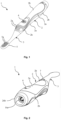
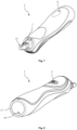
- Fig. 1 to 15 1 generally illustrates an electric toothbrush 1 in accordance with the present invention with an alternative embodiment variant (vibrating drive).
- the electric toothbrush 1 is shown from different sides.
- the electric toothbrush comprises a handle 2, which has a housing made of hard component 2a, which is provided in some areas with soft component 2b in order to increase the grip.
- the toothbrush 1 has an on/off switch 4, which is also coated with soft component 2b.
- a Brush head 3 is applied, which is in Fig. 1 and Fig. 2 has no bristles, so that only the bristle holes 5a are visible on the bristle carrier 5 or brush head, which in this case are designed as blind holes.
- the brush attachment has bristles 5b, which in this embodiment have the same length.
- the end part 26b closes the housing of the handset 2 and surrounds the charging socket 16 as a kind of protective structure.
- the brush attachment 3 has a recess 8 on the back, in which a corresponding cam 7 of the handpiece 2 engages, whereby a predefined pull-off force of the brush attachment 3 can be set.
- the handpiece 2 On the back, the handpiece 2 has a surface with a soft component 2b opposite the on/off switch 4, which in turn ensures a better grip.
- a through hole with a pressure compensation element 6 for degassing the housing interior 19 is provided in the rear end area on the back of the handpiece 2.
- Fig. 6 According to the sectional view in Fig. 6 Firstly, you can see the bristles 5b arranged in the blind holes (bristle holes 5a) of the bristle carrier 5. You can also see the insertion unit 20 inserted into the handpiece 2, which comprises the insertion carrier 21, on which the motor 11 with the eccentric 11a, the on/off switch 4, the battery 12, the printed circuit board 15 and the charging socket 16 with the charging socket housing 16b and the charging socket pin 16a are arranged. The charging socket 16 or the charging socket housing 16b and the charging socket pin 16a are connected via the electrical lines 14 to the printed circuit board 15, which in turn is connected to the battery 12.
- the motor 11 is connected to the printed circuit board 15 via the electrical lines 13 and the on/off switch 4 is arranged on the printed circuit board 15 in such a way that it can close or interrupt the circuit.
- the plug-in unit 20 is thus configured in such a way that a closed circuit can be created with it alone.
- the rear end of the hand part 2 is formed by the end part 26b. The hand part 2 is inserted at the front with its plug-like coupling structure 10 into the corresponding socket-like coupling structure 9 of the brush attachment 3.
- Fig. 7 to 9 illustrate the handpiece 2 or its housing, ie without brush head and without insert unit 20.
- Fig. 7 shows in particular the through hole with pressure compensation element 6 in the rear area of the handle 2 as well as the cam 7 and the plug-like coupling structure 10, which forms the interface to the brush head 3.
- Fig. 8 In particular, the on/off switch 4 overmolded with soft component is shown as well as the housing wall 17 with a locking recess 18 for a corresponding locking lug 29 of the plug-in unit 20, which is described further below.
- at least two, in this case four, locking recesses 18 are provided in the rear housing area, as in Fig. 9 which are arranged opposite one another on the housing wall 17 in the direction of the top and rear.
- positioning aids 19a and 19b for the plug-in unit 20 and the plug-in carrier 21 are provided in the housing interior 19, as well as the stop 19c for the motor 11.
- the direction of insertion for the plug-in unit 20 is indicated by the arrow E.
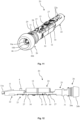
- a plug-in unit 20 according to the invention is shown on its own.
- the plug-in unit 20 comprises the plug-in carrier 21, which is divided into several sections for the individual components.
- the motor carrier 22 for the motor 11 is provided at the front.
- the switch carrier 23 which surrounds the on/off switch 4 (the switch itself is arranged on the printed circuit board).
- the battery carrier 24 into which the battery 12 is inserted, which is in electrical contact with the printed circuit board 15 via soldered contact plates 27 (in this case only the front contact plate is visible).
- the connection carrier 25 through which the electrical lines 14 are led from the printed circuit board 15 to the charging socket 16 in the final device.
- the charging socket 16 is accommodated in the charging device carrier 26.
- the locking lugs 29, which snap into the previously described recesses 18 in the housing wall 17 of the handset 2, are also located on the charging socket carrier 26.
- a locking lug 29 or its wedge-shaped structure (opposite the insertion direction E) is illustrated in a side view.
- the locking lug 29 comprises an insertion bevel 29a which extends at an angle ⁇ from the base line of the locking lug 29, which has a length L 1
- the insertion bevel 29a is followed by the horizontal part 29b, which has a base line with a length L 2 and a vertical wall 29c with a height H which corresponds to the maximum height of the insertion bevel 29a.
- the angle ⁇ defined by the insertion bevel 29a with respect to the base line lies in a range from 10° to 75°, preferably from 15° to 35°.
- the length L 1 of the base line of the insertion bevel 29a is from 0.3 mm to 3 mm, preferably from 0.5 mm to 1.5 mm.
- the height H of the insertion bevel 29a is from 0.1 mm to 1.5 mm, preferably from 0.25 mm to 0.5 mm.
- the height H increases continuously and then merges into the horizontal part 29b.
- the horizontal part 29b comprises the base line with the length L 2 of 0.1 mm to 1 mm, preferably 0.15 mm to 2 mm.
- the height H is between 0.1 mm to 1.5 mm, preferably 0.25 mm to 0.5 mm (ie corresponding to the highest point of the insertion bevel 29a).
- the rear, vertical wall 29c serves for the actual locking into the locking recesses 18 in the housing and accordingly also has the height H.
- the total dimension of the insertion bevel 29a is therefore in the length of L 1 plus L 2 from 0.4 mm to 4 mm, preferably from 0.65 mm to 3.5 mm, in the width (ie perpendicular to the longitudinal axis X or to the insertion direction E) from 0.5 mm to 3 mm, preferably from 0.8 mm to 2 mm and in the height from 0.1 mm to 1.5 mm, preferably from 0.25 mm to 0.5 mm.
- the charging device carrier 26 which accommodates the charging socket 16 with the charging socket pin 16a and the charging socket housing 16b.
- the end part 26b of the charging device carrier 26 surrounds the charging socket 16 or its front end in the manner of a ring-shaped protective element, which is also configured for vertical positioning of the device in that it has a flat outer surface 46.
- Through corresponding openings in the printed circuit board The contact ends of the contact plates 27 protrude through 15, which are soldered to the printed circuit board 15 and ensure the connection of the battery 12 with the printed circuit board 15.
- the printed circuit board 15 is held by holders 30 of the slide-in carrier.
- the motor carrier 22 has two adjacent through openings 22a on its rear side with a partition wall arranged between them.
- the side view of the plug-in unit according to Fig. 12 essentially illustrates once again the issues related to Fig. 10 described parts or components of the plug-in unit 20 according to the invention.
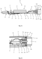
- Fig. 13 a sectional view through the assembled plug-in unit 20 according to Fig. 12 with schematically illustrated components.
- the charging device carrier body 26a encloses the charging socket 16 or the charging socket housing 16b, which surrounds the charging socket pin 16a.
- a corresponding plug of a power supply for charging the device can be plugged onto the charging socket pin 16a.
- the end part 26b surrounds the charging socket 16 or its front end in the manner of a ring-shaped protective element, which is also configured for vertical positioning of the device in that it has a flat outer surface 46 (cf. Fig. 11 ).
- One electrical line 14 is connected to the charging socket housing 16b and the other electrical line 14 is connected to the charging socket pin 16a.
- the electrical lines 14 are led from the printed circuit board 15 through the connecting carrier 25 to the charging socket housing 16b or to the charging socket plug 16a.
- the charging socket housing 16b further comprises hook-shaped locking geometries 16c by means of which the charging socket 16 is held in the charging device carrier body 26a.
- the end part 26b comprises a circumferential projection 45 at its end facing the charging device carrier body 26a, which can cooperate in a sealing manner with an adjacent soft component area 2b of the housing.
- the charging device carrier body 26a has at its outer circumference also has two circumferential grooves 33a and 34a, each of which serves to accommodate a corresponding sealing element or O-ring.
- only the groove 34a located towards the end part 26b is covered with an O-ring 34b.
- This form of sealing between the housing and the charging device carrier is usually sufficient.
- the groove 33a can also be covered with an additional sealing element or O-ring 33b. It is also conceivable that only the groove 33a is covered with a sealing element or O-ring 33b.
- the printed circuit board 15 is held in position by the holders 30 of the insert carrier 21.
- the electrical lines 13 are led from the printed circuit board 15 under the switch carrier 23 into the motor carrier 22 and are each preferably connected there to a connection on the back of the motor 11.
- FIG. 14 an embodiment of the inventive insert unit 20 is shown, in which the charging device carrier 26 has a two-part structure.
- the end part 26b is locked to the charging device carrier body 26a with locking devices 47 and can thus be inserted into the hand part 2 together with this or as part of the insert unit 20.
- a further seal is created between the projection 45 and the adjacent soft component 2b at the rear end of the hand part, ie in addition to the circumferential seal between the sealing element or O-ring 34b and the inside of the housing wall 17.
- the charging socket 16 is freely accessible from the outside through the charging opening 35.
- the through hole with pressure compensation element is introduced into the housing wall 17 towards the rear.
- the flattened area 31 supports the connection carrier 25 against the inside of the housing wall 17.
- the charging device carrier body 26a is supported circumferentially on the inside of the housing wall 17.
- the end part 26b closes off the handset 2 towards the outside and thus forms part of the outer surface of the handset, in particular in the horizontal direction with its outer circumference 49 but also in the vertical direction by means of the flat outer surface 46.
- the charging socket 16 also forms part of the outer surface in the vertical direction with the outer part of the charging socket housing 16b and the rear end of the charging socket pin 16a.
- a further embodiment of the plug-in unit 20 according to the invention is shown, in which the charging device carrier has a two-part structure.
- the end part 26b is plugged laterally onto the charging device carrier body 26a, whereby a clamping effect is preferably achieved and whereby the end part 26b as part of the plug-in unit 20 is pushed into the hand part with it.
- a seal is created between the projection 45 and the adjacent soft component 2b at the rear end of the hand part 2, ie in addition to the seals between the end part 26b and the inside of the housing wall 17 and between the end part 26b and the charging device carrier body 26a in the axial direction.
- the circumferential seal between the end part 26b and the inside of the housing wall 17 is achieved by means of the sealing element 36b or O-ring in the groove 36a at the front end of the end part.
- the axial sealing between the end part 26b and the loading device carrier body 26a is achieved by means of the sealing element 37b or O-ring in the groove 37a at the rear end of the loading device carrier body 26a, wherein the end part 26b presses against the O-ring 37b with a retaining projection 48.
- the end part can be pushed into the device together with the charging device carrier body or the rest of the plug-in unit 20.
- the charging socket 16 is freely accessible from the outside through the charging opening 35.
- the through hole with pressure compensation element 6 is introduced into the housing wall 17 towards the rear.
- the flattened area 31 supports the connecting carrier 25 against the inside of the housing wall 17.
- the charging device carrier body 26a is in turn supported circumferentially on the inside of the housing wall 17.
- the end part 26b closes off the handset 2 towards the outside and thus forms part of the outer surface of the handset 2, in particular in the horizontal direction with its outer circumference 49 but also in the vertical direction by means of the flat outer surface 46.
- the charging socket 16 also forms part of the outer surface in the vertical direction with the outer part of the charging socket housing 16b and approximately the rear end of the charging socket pin 16a.
- the electric toothbrush 1 comprises a handpiece 2, which has a housing made of hard component 2a. On the top, the toothbrush 1 has an on/off switch 4. Above the on/off switch 4, signal elements 38, such as LED lights, are arranged in the housing, which may indicate the operating and/or charging status of the device.
- a closing part 26b is arranged, which has an opening for the charging socket 16 and which closes the handpiece 2 towards the outside and thus forms part of the outer surface of the handpiece, in particular in the longitudinal direction with its flat outer surface 50 and also perpendicular to the longitudinal direction with its outer circumference 51.
- the through hole with pressure compensation element 6 is also arranged in the closing part 26b, towards the flat outer surface 50.
- storage structures 39 can also be seen for safely storing the handpiece 2 on the back, ie with the bristles 5b facing upwards.
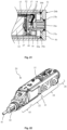
- Fig. 21 shows a cross-sectional view of the rear end of the handle of an electric toothbrush with inserted insert unit according to the Fig. 16 to 20 .
- the end part 26b lies flush with the rear end of the housing wall 17, with the flat outer surface 50 forming part of the outer surface of the handpiece 2 in the longitudinal direction and the outer circumference 51 forming part of the outer surface of the handpiece perpendicular to the longitudinal direction.
- the end part 26b has a sealing element or an O-ring 36b which is inserted into a corresponding groove 36a.
- the charging device carrier body 26a For axial sealing of the charging device carrier body 26a against the end part 26b, the charging device carrier body 26a has a groove 37a into which a sealing element 37b or an O-ring is inserted, onto which the end part 26a presses with its inside in the axial direction.
- the end part 26b locks into the housing here and is not inserted into the handset with the plug-in unit 20, but is attached separately to the rear end of the handset, with the end part 26b preferably locking into the housing wall 17.
- the end part 26b as such is not part of the plug-in unit 20 or the charging device carrier 26b in this embodiment.
- the charging device carrier body 26a is here spring-mounted by means of a spring bearing 40 on a support structure 52 of the plug-in unit 20, which adjoins the battery 12 or the battery carrier 24.
- the electrical lines 14 coming from the printed circuit board 15 are connected to the contacts of the charging socket 16.
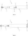
- the insert unit 20 for the electric toothbrush is inserted according to the Fig. 16 to 21 illustrated in perspective view from the front and rear as well as in the side view.
- the printed circuit board 15 is arranged on the top of the plug-in carrier 21, the plug-in carrier 20 being constructed in the manner of a monoframe, which has a gear carrier 43 (for the gear that generates the rotating-oscillating movement), a motor carrier or a motor zone 22, a battery carrier or a battery zone 24 and a charging device carrier 26 or a charging device carrier zone.
- the key element 42 (as an interface to the brush attachment 3) is arranged at the front end of the plug-in unit 20 and encloses the drive shaft 41.
- the plug-in unit 20 is also configured in such a way that a closed circuit can be produced with it alone.
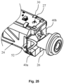
- Fig. 25 Finally, a detailed view of the rear end of the slide-in unit 20 is shown according to the Fig. 22 to 24 illustrated. It can be seen that the loading device carrier 26 is spring-mounted on the support structure 52 of the insertion unit 20 via a first spring clip 40a of the spring bearing 40 and a second spring clip 40b of the spring bearing 40.
- the spring clips 40a and 40b are arranged independently of one another between the support structure 52 and the loading device carrier 26. In this way, a particularly effective length compensation function can be provided (the end part 26b presses in this embodiment the insertion unit 20 into the housing).
- the holders 30 on the battery carrier 24 can be seen, which are in engagement with the top of the printed circuit board 15.
- a contact plate 27 with a contact end protrudes through the printed circuit board 15.
- the present disclosure also includes embodiments with any combination of features mentioned or shown above or below for various embodiments. It also includes individual features in the figures, even if they are shown there in connection with other features and/or are not mentioned above or below.
- the alternatives of embodiments described in the figures and the description and individual alternatives of their features can also be excluded from the subject matter of the invention or from the disclosed subject matters.
- the disclosure includes embodiments that exclusively include the features described in the claims or in the exemplary embodiments, as well as those that include additional other features.
Landscapes
- Health & Medical Sciences (AREA)
- Engineering & Computer Science (AREA)
- Dentistry (AREA)
- Epidemiology (AREA)
- Life Sciences & Earth Sciences (AREA)
- Animal Behavior & Ethology (AREA)
- General Health & Medical Sciences (AREA)
- Public Health (AREA)
- Veterinary Medicine (AREA)
- Computer Networks & Wireless Communication (AREA)
- Power Engineering (AREA)
- Brushes (AREA)
Priority Applications (3)
| Application Number | Priority Date | Filing Date | Title |
|---|---|---|---|
| EP23170573.2A EP4454604A1 (fr) | 2023-04-28 | 2023-04-28 | Unité d'insertion pour appareil électrique de soins personnels |
| PCT/EP2024/061615 WO2024223867A1 (fr) | 2023-04-28 | 2024-04-26 | Unité insérable pour appareil électrique de soins personnels |
| EP24722270.6A EP4701573A1 (fr) | 2023-04-28 | 2024-04-26 | Unité insérable pour appareil électrique de soins personnels |
Applications Claiming Priority (1)
| Application Number | Priority Date | Filing Date | Title |
|---|---|---|---|
| EP23170573.2A EP4454604A1 (fr) | 2023-04-28 | 2023-04-28 | Unité d'insertion pour appareil électrique de soins personnels |
Publications (1)
| Publication Number | Publication Date |
|---|---|
| EP4454604A1 true EP4454604A1 (fr) | 2024-10-30 |
Family
ID=86282572
Family Applications (2)
| Application Number | Title | Priority Date | Filing Date |
|---|---|---|---|
| EP23170573.2A Pending EP4454604A1 (fr) | 2023-04-28 | 2023-04-28 | Unité d'insertion pour appareil électrique de soins personnels |
| EP24722270.6A Pending EP4701573A1 (fr) | 2023-04-28 | 2024-04-26 | Unité insérable pour appareil électrique de soins personnels |
Family Applications After (1)
| Application Number | Title | Priority Date | Filing Date |
|---|---|---|---|
| EP24722270.6A Pending EP4701573A1 (fr) | 2023-04-28 | 2024-04-26 | Unité insérable pour appareil électrique de soins personnels |
Country Status (2)
| Country | Link |
|---|---|
| EP (2) | EP4454604A1 (fr) |
| WO (1) | WO2024223867A1 (fr) |
Citations (4)
| Publication number | Priority date | Publication date | Assignee | Title |
|---|---|---|---|---|
| WO2016117580A1 (fr) | 2015-01-21 | 2016-07-28 | 株式会社大塚製薬工場 | Procédé de production d'orifice et procédé de production de poche de solution médicale |
| US20170007384A1 (en) * | 2015-07-08 | 2017-01-12 | Water Pik, Inc. | Oral cleansing device with energy conservation |
| WO2019072994A1 (fr) | 2017-10-11 | 2019-04-18 | Trisa Holding Ag | Brosse amovible, poignée de brosse à dents électrique et brosse à dents électrique pourvue de la poignée de brosse à dents électrique et de la brosse amovible |
| WO2022128207A1 (fr) | 2020-12-18 | 2022-06-23 | Trisa Holding Ag | Unité d'entraînement pour une pièce à main de brosse à dents électrique, pièce à main de brosse à dents électrique, méthode de production d'une pièce à main de brosse à dents électrique, tête de brosse pour une pièce à main de brosse à dents électrique, et brosse à dents électrique |
Family Cites Families (1)
| Publication number | Priority date | Publication date | Assignee | Title |
|---|---|---|---|---|
| EP4233639B1 (fr) | 2015-05-04 | 2025-10-15 | Trisa Holding AG | Appareil électrique de soins corporels |
-
2023
- 2023-04-28 EP EP23170573.2A patent/EP4454604A1/fr active Pending
-
2024
- 2024-04-26 EP EP24722270.6A patent/EP4701573A1/fr active Pending
- 2024-04-26 WO PCT/EP2024/061615 patent/WO2024223867A1/fr not_active Ceased
Patent Citations (4)
| Publication number | Priority date | Publication date | Assignee | Title |
|---|---|---|---|---|
| WO2016117580A1 (fr) | 2015-01-21 | 2016-07-28 | 株式会社大塚製薬工場 | Procédé de production d'orifice et procédé de production de poche de solution médicale |
| US20170007384A1 (en) * | 2015-07-08 | 2017-01-12 | Water Pik, Inc. | Oral cleansing device with energy conservation |
| WO2019072994A1 (fr) | 2017-10-11 | 2019-04-18 | Trisa Holding Ag | Brosse amovible, poignée de brosse à dents électrique et brosse à dents électrique pourvue de la poignée de brosse à dents électrique et de la brosse amovible |
| WO2022128207A1 (fr) | 2020-12-18 | 2022-06-23 | Trisa Holding Ag | Unité d'entraînement pour une pièce à main de brosse à dents électrique, pièce à main de brosse à dents électrique, méthode de production d'une pièce à main de brosse à dents électrique, tête de brosse pour une pièce à main de brosse à dents électrique, et brosse à dents électrique |
Also Published As
| Publication number | Publication date |
|---|---|
| WO2024223867A1 (fr) | 2024-10-31 |
| EP4701573A1 (fr) | 2026-03-04 |
Similar Documents
| Publication | Publication Date | Title |
|---|---|---|
| EP3928659B1 (fr) | Appareil électrique de soins corporels | |
| EP3831242B1 (fr) | Brosse à dents pourvue de soies moulées par injection | |
| EP2130454B1 (fr) | Procédé de fabrication de brosses à dents à poils non ancrés | |
| EP3694441B1 (fr) | Poignée de brosse à dents électrique | |
| EP3381404B1 (fr) | Brosse de soin corporelle électrique | |
| EP2862478B1 (fr) | Brosse à dents et son procédé de fabrication | |
| EP1864588A2 (fr) | Brosse à dents et procédé destiné à sa fabrication | |
| EP4262621B1 (fr) | Poigné de brosse à dents électrique et procédé de fabrication d'une poigné de brosse à dents électrique | |
| EP1494561B1 (fr) | Brosse a dents et procede de fabrication | |
| EP2664298B1 (fr) | Brosse à dents électrique, connecteur de la tête de brosse et poignée pour une brosse à dents électrique | |
| EP3865088B1 (fr) | Dispositif de brosse enfichable | |
| DE102012010415B4 (de) | Verfahren zum Herstellen von Bürsten, Borstenträger sowie Bürste | |
| EP4454604A1 (fr) | Unité d'insertion pour appareil électrique de soins personnels | |
| DE102011102624B4 (de) | Halteelement und Halteanordnung zum Halten einer Sicherung sowie Sicherungssystem | |
| WO2023232822A1 (fr) | Produit d'hygiène bucco-dentaire | |
| DE102011017099A1 (de) | Verfahren zur Herstellung von Zahnbürsten | |
| DE102007037940A1 (de) | Verfahren zur Erzeugung einer formschlüssigen Verbindung sowie mittels Formschluss steckverbundene Teile |
Legal Events
| Date | Code | Title | Description |
|---|---|---|---|
| PUAI | Public reference made under article 153(3) epc to a published international application that has entered the european phase |
Free format text: ORIGINAL CODE: 0009012 |
|
| STAA | Information on the status of an ep patent application or granted ep patent |
Free format text: STATUS: THE APPLICATION HAS BEEN PUBLISHED |
|
| AK | Designated contracting states |
Kind code of ref document: A1 Designated state(s): AL AT BE BG CH CY CZ DE DK EE ES FI FR GB GR HR HU IE IS IT LI LT LU LV MC ME MK MT NL NO PL PT RO RS SE SI SK SM TR |
|
| STAA | Information on the status of an ep patent application or granted ep patent |
Free format text: STATUS: REQUEST FOR EXAMINATION WAS MADE |
|
| 17P | Request for examination filed |
Effective date: 20250430 |
|
| STAA | Information on the status of an ep patent application or granted ep patent |
Free format text: STATUS: EXAMINATION IS IN PROGRESS |
|
| 17Q | First examination report despatched |
Effective date: 20250812 |
|
| GRAP | Despatch of communication of intention to grant a patent |
Free format text: ORIGINAL CODE: EPIDOSNIGR1 |
|
| STAA | Information on the status of an ep patent application or granted ep patent |
Free format text: STATUS: GRANT OF PATENT IS INTENDED |
|
| INTG | Intention to grant announced |
Effective date: 20260331 |