EP4454789A1 - Dispositif et procédé de fabrication additive d'un composant - Google Patents
Dispositif et procédé de fabrication additive d'un composant Download PDFInfo
- Publication number
- EP4454789A1 EP4454789A1 EP23170368.7A EP23170368A EP4454789A1 EP 4454789 A1 EP4454789 A1 EP 4454789A1 EP 23170368 A EP23170368 A EP 23170368A EP 4454789 A1 EP4454789 A1 EP 4454789A1
- Authority
- EP
- European Patent Office
- Prior art keywords
- raw material
- granular raw
- carrier
- electrode
- component
- Prior art date
- Legal status (The legal status is an assumption and is not a legal conclusion. Google has not performed a legal analysis and makes no representation as to the accuracy of the status listed.)
- Pending
Links
Images


Classifications
-
- B—PERFORMING OPERATIONS; TRANSPORTING
- B22—CASTING; POWDER METALLURGY
- B22F—WORKING METALLIC POWDER; MANUFACTURE OF ARTICLES FROM METALLIC POWDER; MAKING METALLIC POWDER; APPARATUS OR DEVICES SPECIALLY ADAPTED FOR METALLIC POWDER
- B22F10/00—Additive manufacturing of workpieces or articles from metallic powder
- B22F10/20—Direct sintering or melting
- B22F10/28—Powder bed fusion, e.g. selective laser melting [SLM] or electron beam melting [EBM]
-
- B—PERFORMING OPERATIONS; TRANSPORTING
- B22—CASTING; POWDER METALLURGY
- B22F—WORKING METALLIC POWDER; MANUFACTURE OF ARTICLES FROM METALLIC POWDER; MAKING METALLIC POWDER; APPARATUS OR DEVICES SPECIALLY ADAPTED FOR METALLIC POWDER
- B22F10/00—Additive manufacturing of workpieces or articles from metallic powder
- B22F10/30—Process control
- B22F10/37—Process control of powder bed aspects, e.g. density
-
- B—PERFORMING OPERATIONS; TRANSPORTING
- B33—ADDITIVE MANUFACTURING TECHNOLOGY
- B33Y—ADDITIVE MANUFACTURING, i.e. MANUFACTURING OF THREE-DIMENSIONAL [3D] OBJECTS BY ADDITIVE DEPOSITION, ADDITIVE AGGLOMERATION OR ADDITIVE LAYERING, e.g. BY 3D PRINTING, STEREOLITHOGRAPHY OR SELECTIVE LASER SINTERING
- B33Y10/00—Processes of additive manufacturing
-
- B—PERFORMING OPERATIONS; TRANSPORTING
- B33—ADDITIVE MANUFACTURING TECHNOLOGY
- B33Y—ADDITIVE MANUFACTURING, i.e. MANUFACTURING OF THREE-DIMENSIONAL [3D] OBJECTS BY ADDITIVE DEPOSITION, ADDITIVE AGGLOMERATION OR ADDITIVE LAYERING, e.g. BY 3D PRINTING, STEREOLITHOGRAPHY OR SELECTIVE LASER SINTERING
- B33Y30/00—Apparatus for additive manufacturing; Details thereof or accessories therefor
-
- B—PERFORMING OPERATIONS; TRANSPORTING
- B33—ADDITIVE MANUFACTURING TECHNOLOGY
- B33Y—ADDITIVE MANUFACTURING, i.e. MANUFACTURING OF THREE-DIMENSIONAL [3D] OBJECTS BY ADDITIVE DEPOSITION, ADDITIVE AGGLOMERATION OR ADDITIVE LAYERING, e.g. BY 3D PRINTING, STEREOLITHOGRAPHY OR SELECTIVE LASER SINTERING
- B33Y50/00—Data acquisition or data processing for additive manufacturing
- B33Y50/02—Data acquisition or data processing for additive manufacturing for controlling or regulating additive manufacturing processes
-
- B—PERFORMING OPERATIONS; TRANSPORTING
- B22—CASTING; POWDER METALLURGY
- B22F—WORKING METALLIC POWDER; MANUFACTURE OF ARTICLES FROM METALLIC POWDER; MAKING METALLIC POWDER; APPARATUS OR DEVICES SPECIALLY ADAPTED FOR METALLIC POWDER
- B22F10/00—Additive manufacturing of workpieces or articles from metallic powder
- B22F10/10—Formation of a green body
- B22F10/14—Formation of a green body by jetting of binder onto a bed of metal powder
-
- B—PERFORMING OPERATIONS; TRANSPORTING
- B22—CASTING; POWDER METALLURGY
- B22F—WORKING METALLIC POWDER; MANUFACTURE OF ARTICLES FROM METALLIC POWDER; MAKING METALLIC POWDER; APPARATUS OR DEVICES SPECIALLY ADAPTED FOR METALLIC POWDER
- B22F10/00—Additive manufacturing of workpieces or articles from metallic powder
- B22F10/30—Process control
- B22F10/38—Process control to achieve specific product aspects, e.g. surface smoothness, density, porosity or hollow structures
-
- B—PERFORMING OPERATIONS; TRANSPORTING
- B22—CASTING; POWDER METALLURGY
- B22F—WORKING METALLIC POWDER; MANUFACTURE OF ARTICLES FROM METALLIC POWDER; MAKING METALLIC POWDER; APPARATUS OR DEVICES SPECIALLY ADAPTED FOR METALLIC POWDER
- B22F12/00—Apparatus or devices specially adapted for additive manufacturing; Auxiliary means for additive manufacturing; Combinations of additive manufacturing apparatus or devices with other processing apparatus or devices
- B22F12/60—Planarisation devices; Compression devices
-
- B—PERFORMING OPERATIONS; TRANSPORTING
- B22—CASTING; POWDER METALLURGY
- B22F—WORKING METALLIC POWDER; MANUFACTURE OF ARTICLES FROM METALLIC POWDER; MAKING METALLIC POWDER; APPARATUS OR DEVICES SPECIALLY ADAPTED FOR METALLIC POWDER
- B22F2999/00—Aspects linked to processes or compositions used in powder metallurgy
Definitions
- the invention relates to devices and methods for the additive manufacturing of components from a granular raw material.
- Additive or generative manufacturing (3D printing) has established itself as an industrially applicable manufacturing technology, particularly in aerospace engineering, medical technology and mechanical engineering.
- Additive manufacturing refers to manufacturing techniques in which material is applied layer by layer to create three-dimensional objects (components or workpieces).
- An example of an additive manufacturing technique is laser beam melting. It is often used for the additive manufacturing of metallic components from metal powders. A layer of metal powder is applied to a construction plate using a coater. Thermal energy is selectively applied to this metal powder layer using a laser beam, thereby melting the metal powder. The subsequent cooling and solidification of the melted metal powder creates a firm bond with the layer below. The construction plate is then lowered by one layer height and another layer of metal powder is applied using a coater. The cyclical manufacturing process is repeated until the component has been completely built up layer by layer.
- laser beam melting presents process-specific challenges.
- One of these challenges is achieving the most homogeneous layer of the applied metal powder with the smoothest or most even surface possible. This not only enables higher relative densities of the additively manufactured components to be achieved, but often also improves the mechanical and optical properties of the components.
- the metal powder is often applied by means of linear or rotary movement of a device attached to the coater. attached coater lip onto the underlying metal powder layer. Since individual metal powder particles can be pushed in the coating direction by the coater with a typical particle size distribution of 20 to 55 ⁇ m and a typical powder layer thickness of 20 to 100 ⁇ m, grooves can form in the powder layer surface. These grooves can impair the component quality, in particular the surface quality.
- the powder application by means of the coater results in an inhomogeneous powder distribution in the coating direction due to the different setting behavior of metal powder particles of different particle sizes.
- the coating lip is damaged, the depth or height of the grooves is many times greater. Damage to the coating lip occurs in particular when component elements bulge out of the powder as a result of thermal distortion during the manufacturing process or when their support structures detach from the building board. During the subsequent coating, the coating lip collides with the component elements protruding from the powder and is damaged. Alternatively, the coating lip can also be damaged by splashes of metallic melt from the melt pool.
- the coater lips are typically replaced after each production process, which results in additional costs and reduces productivity.
- the unevenness of the coater lip caused by collisions is transferred as a negative to the powder layer in the subsequent coating processes, which can severely impair the homogeneity and evenness or smoothness of the surface. These grooves can be transferred to the components to be manufactured. In many cases, this leads to these components being rejected or requires additional work steps in the form of component post-processing.
- the state of the art contains numerous proposed solutions for achieving the most homogeneous layers of the granular raw material, such as a metal powder, with the smoothest or most even surface possible in devices and processes for the additive manufacturing of components from a granular raw material.
- the granular raw material such as a metal powder
- the published patent application WO 2020/260785 A1 suggests, for example, using a vibrating device to cause the applied powder to oscillate mechanically or vibrate, thereby leveling out any irregularities and/or unevenness that may arise when the powder is applied.
- a vibrating device to cause the applied powder to oscillate mechanically or vibrate, thereby leveling out any irregularities and/or unevenness that may arise when the powder is applied.
- the coater is set into mechanical oscillations or vibrations with the help of an ultrasonic generator in order to remove any existing irregularities and/or unevenness by shearing and friction movements.
- a powder spreading device is proposed in which mechanical oscillations or vibrations are used to apply powder without contact and thus as homogeneously and smoothly as possible. With the help of electrostatic fields, the powder particles are additionally accelerated in order to increase the density of the applied powder.
- the WO 2016/205719 A1 also uses electrostatic fields to recompact the powder.
- electrostatic fields can be used not only to accelerate powder particles and (re-)compact the applied powder, but also to apply it to a building plate without contact.
- the methods proposed in the state of the art often affect not only the applied powder, but also the component. This can damage the component, parts of it or any support structures that are necessary for the construction of the component. This is especially true when larger masses such as the coater or the construction plate are set in vibration or the applied powder is re-compacted using electrostatic forces.
- the component and any support structures can also be damaged if individual powder particles hit the component and the support structures at high speed and in an uncontrolled manner. This not only affects the quality of the components, but can also result in additional work steps in the form of component re-processing or even lead to component rejection.
- the object of the invention is to provide devices and methods for the additive manufacturing of components from a granular raw material, with which the quality of the components can be improved or a high quality of the components can be ensured.
- the particles of the granular raw material in the holder of the carrier are subjected to alternating voltage, the particles of the granular raw material are alternately attracted or repelled by the alternating electric field generated by the alternating voltage. In this way, the particles of the granular raw material are set in vibrations. and/or vibrations. Typically, the part of the granular raw material closest to the electrode is subjected to oscillations and/or vibrations.
- the oscillations and/or vibrations lead to the reduction and equalization of irregularities and/or unevenness of at least one part of the granular raw material that can arise when filling the carrier receptacle with the layer of granular raw material (e.g. furrows). In many cases, this is manifested by the particles of at least one part of the granular raw material being distributed more evenly in the carrier receptacle. In addition, the surface of at least one part of the granular raw material is leveled or smoothed and the granular raw material or at least part of it is compacted. Furthermore, irregularities in the distribution of the particles in terms of size can be equalized.
- the at least one part of the granular raw material is the layer or part of the layer of granular raw material that was last introduced into the carrier receptacle in order to be selectively solidified next to produce the component.
- the removal and/or compensation of the aforementioned irregularities and/or unevenness therefore in many cases directly results in an improvement in the quality of the components produced with the proposed device.
- Parts of the raw material that have already solidified are generally subjected to far less oscillations and/or vibrations due to their greater mass, i.e. the amplitude of the oscillations and/or vibrations of these parts is smaller than the amplitude of the oscillations and/or vibrations exhibited by the particles of the granular raw material.
- This difference in the amplitude of the oscillations and/or vibrations represents a selection that does not occur or occurs to a far lesser extent in the known devices, for example with an oscillating device.
- the selection particularly affects the component or parts thereof or any support structures, which are typically subjected to less oscillations than the particles of the granular raw material.
- the selection can be further enhanced by connecting the component and/or any support structures to the carrier during the manufacture of the component by the component production unit, so that the component and/or any support structures cannot oscillate or at least cannot oscillate completely independently of the carrier.
- the proposed device can therefore avoid the disadvantages that arise from movement of the already solidified parts, in particular the component, parts thereof or any supporting structures. This not only has a positive effect on the quality of the component, but also leads to less waste and reduces the effort required for any subsequent processing.
- the movement of the particles induced by the alternating voltage is not necessarily orderly, but is typically chaotic. These impacts and/or collisions usually lead to the aforementioned irregularities and unevenness of at least part of the granular raw material being reduced or evened out. If the excitation of the particles by the alternating voltage is switched off, the particles come to rest again and assume a resting state or resting positions. During the transition from the state excited by the alternating voltage to this resting state, the particles arrange themselves regularly. With the help of the applied alternating voltage, the particles can therefore not only be distributed more evenly, but also brought into a more regular arrangement. This uniform distribution and regular arrangement leads, among other things, to a smoothing of the surface of the granular raw material, in particular of the part of the granular raw material that is available for selective solidification by the component production unit.
- the frequency of the alternating voltage is preferably in the range from 3 Hz to 3 kHz, particularly preferably in the range from 30 Hz to 300 Hz.
- undesirable electrical excitations can be avoided or reduced to an acceptable level, i.e. the excitation of the particles of the granular raw material can thus be essentially limited to mechanical oscillations and/or vibrations.
- the mains frequency of 50 Hz or 60 Hz, for example, which means that components for converting and/or converting the mains frequency can be saved.
- the alternating voltage can be applied, for example, between the carrier or a part of the carrier and the electrode.
- the application can also be carried out using another electrode, which does not have to be in direct electrical contact with the carrier.
- the two electrodes are preferably arranged in such a way or can be moved or moved in such a way that the carrier's receptacle is located between the electrode and the other electrode.
- the granular raw material can be a metal powder, for example a titanium, steel, cobalt-chromium or copper powder or a mixture of these.
- a metal powder for example a titanium, steel, cobalt-chromium or copper powder or a mixture of these.
- other granular raw materials in particular ceramic powders, plastic granules or sand.
- the particles of the granular raw material can therefore be powder particles, grains of sand and/or plastic beads. The particles can have different shapes and sizes.
- the component is a component that is ready for use.
- it can also be a green body or an intermediate product that needs to be further processed or reworked in subsequent work steps.
- the alternating voltage can be in the low voltage range (up to 1000 V) or high voltage range ( ⁇ 1000 V).
- High voltages generally require special protective measures to avoid arcing and electrical excitation.
- Low voltages are therefore generally easier to handle than high voltages.
- lower voltages generate less strong electrical fields, so that the granular raw material or at least part of the granular raw material is also less subject to oscillations and/or vibrations than when higher voltages are used.
- an appropriate balance must be found between the effort required for the protective measures and the result to be achieved of a distribution of the granular raw material that is as homogeneous as possible with a surface that is as smooth or even as possible.
- the alternating voltage is therefore preferably in the high voltage range, i.e. it has effective values in the range from 1 kV to 100 kV, particularly preferably in the range from 3 kV to 30 kV or 6 kV to 15 kV. In many cases, optimal results are achieved for an effective value of 12 kV.
- the alternating voltage can have different temporal profiles. It can have a rectangular profile, a triangular profile or a sinusoidal or cosinusoidal profile.
- the alternating voltage can also have a profile that represents a superposition of a rectangular, triangular, sinusoidal and/or cosinusoidal profile.
- the choice of profile can improve the homogenization and/or compaction of the granular raw material or of at least part of the granular raw material or the associated surface properties.
- the electrode is preferably designed as a metal plate.
- the electrode can also be insulated with a thermally resistant material.
- the thermally resistant material can be glass or ceramic, for example.
- the electrode and/or the carrier can be designed to be movable. In many cases, this makes it easier to fill the holder with granular raw material, in particular with a new layer of granular raw material, for example with the help of a coater and a coater lip or a coater brush.
- the homogenization and/or compaction of the granular raw material or of at least part of the granular raw material or the associated surface properties therefore depend on the distance between the electrode and the holder of the carrier.
- the electrode, the carrier and the control system can therefore be designed and set up to move the electrode at a predetermined distance from the holder of the carrier.
- the specified distance can, for example, be in a range from 0.1 mm to 10 mm.
- the specified distance is preferably in a range from 0.5 mm to 5 mm.
- the movement of the electrode at a predetermined distance from the carrier holder can also be carried out as part of a linear movement or translation. In many cases, this makes it easier to supply the electrode with alternating voltage.
- the result of the homogenization and/or compaction of the granular raw material or of at least a portion of the granular raw material or the associated surface properties depend on the speed at which the electrode and/or the carrier is moved. The best results are achieved when the electrode and/or the carrier are moved as evenly as possible.
- the electrode, the carrier and the control system can therefore be designed and configured to move the electrode at a predetermined speed and/or a predetermined speed profile, at least in the area where the carrier is received.
- the speed profile shows higher speeds for the parts of the electrode that are further away from the axis of rotation.
- the speed profile can also be chosen in such a way that the electrode can be moved quickly towards the support holder and the electrode can be moved quickly away from the holder after homogenization and/or compaction. This can, among other things, shorten the construction time of the components that can be manufactured using the proposed devices.
- Process steps 2 to 4 are usually repeated until the component is completely manufactured or finished.
- the quality of the component can often be significantly improved, particularly by repeatedly applying the third process step.
- the proposed method can be improved with one of the proposed devices with which the electrode can be moved at a predetermined distance from the support holder.
- the electrode when carrying out the third method step described above, can be moved at a predetermined distance from the support holder and the distance can be selected in order to optimize the removal and/or compensation of any irregularities and/or unevenness of at least one part of the granular raw material by the mechanical oscillations and/or vibrations.
- the distance at which the reduction and/or compensation of any irregularities and/or unevenness of at least a part of the granular raw material can be optimized by the mechanical oscillations and/or vibrations can be for example, be determined using measurements in which a certain surface property of at least one part of the granular raw material in the holder of the carrier is determined for different distances and the distance is selected at which the surface property has a very good or the best value. These measurements can be carried out, for example, using a profilometer to determine, for example, the maximum height difference that the at least one part has, or the standard deviation from an average height of the height profile of at least one part of the granular raw material determined with the profilometer.
- the optimal distance in these cases would be the distance at which the maximum height difference or the standard deviation has the smallest value. It is also possible to use other measuring methods and look at other properties. For example, the surface of the granular raw material can be photographed and the surface texture can be determined using image processing methods. For this purpose, the contrast of the images or the maximum brightness difference can be used, for example.
- the density of the granular raw material and/or the distribution of the particles according to size can also be optimized. A combination of these properties can also be the subject of optimization.
- the measurements do not necessarily have to be carried out on granular raw material in the carrier's receptacle.
- Reference containers and/or test equipment can also be used for this purpose, which preferably have properties that are comparable to the properties of the carrier's receptacle. These include geometric dimensions such as height, width and depth, shape and material of the carrier or container.
- the surface of the granular raw material or at least part of the granular raw material in the holder of the carrier can still have small cracks, grooves and/or dents even after the third process step described above.
- these small cracks, grooves and/or dents look like the cracks, grooves and/or dents of an orange peel.
- these orange peel effects can be quantified using the measurements described above and reduced or even avoided by choosing the right distance. Reducing or avoiding the orange peel effects also represents an optimization of the reduction and/or compensation of any irregularities and/or unevenness of at least part of the granular raw material caused by the mechanical oscillations and/or vibrations.
- the method can also be improved with the proposed devices, with which the electrode can be positioned not only at a predetermined distance from the support can be moved, but also at a predetermined speed and/or a predetermined speed profile.
- the electrode can thus be moved at a predetermined speed and/or a predetermined speed profile when carrying out the third method step described above and the predetermined speed and/or the predetermined speed profile can be selected in order to optimize the removal and/or compensation of any irregularities and/or unevenness of the at least part of the granular raw material by the mechanical oscillations and/or vibrations.
- the optimal speed and/or the optimal speed profile can also be determined using the measurements described above. Likewise, by choosing the correct predetermined speed, the orange peel effects described above can be reduced or even avoided.
- the predetermined speed and/or the predetermined speed profile can, for example, have a value in the range of 5 to 200 mm/s, preferably 20 to 50 mm/s, particularly preferably 30 to 40 mm/s. In many cases, the best results are achieved when the predetermined speed and/or the predetermined speed profile has a value of 35 mm/s.
- the best result is achieved when both the distance and the specified speed and/or the specified speed profile are selected to optimize the removal and/or compensation of any irregularities and/or unevenness of at least part of the granular raw material by the mechanical oscillations and/or vibrations.
- the orange peel effects mentioned can be reduced even further in this way and in many cases even completely eliminated or reduced to a level that these effects are no longer significant.
- the control of one of the proposed devices can be set up to carry out the steps of one of the methods just proposed - apart from the step of providing.
- One solution to the problem therefore also consists in a computer program that includes instructions that cause a control of one of the proposed devices to carry out the steps of one of the proposed methods after the device has been provided.
- a computer-readable medium on which the computer program just described is also a solution to the problem.
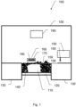
- Fig. 1 shows a device 100 for the additive production of a component 110.
- the component 110 is located on a construction plate 120.
- the construction plate 120 is delimited by carrier elements 130.
- the carrier elements 130 and the construction plate 120 form a carrier with a receptacle.
- granular raw material 140 is located next to the component 110.
- the construction plate 120 can only be delimited by one carrier element 130.
- the construction plate 120 is located, for example, in a correspondingly shaped recess in the carrier element 130 and can also be moved back and forth in this recess in accordance with the additive manufacturing process.
- it can also be limited by more than two carrier elements 130.
- a one-piece design of the carrier with the holder is also possible.
- the construction plate 120 has in the Fig. 1 shown embodiment has a substantially rectangular base area. In other embodiments, it can also have other base areas, for example a substantially square, circular or oval base area.
- the in Fig. 1 The granular raw material 140 shown was introduced into the holder of the carrier by a coater 150 with a coater brush 155.
- the coater 150 with the coater brush 155 is moved in a linear motion over the holder.
- the coater 150 fills the holder with a layer of granular raw material 140. Any excess raw material applied is removed again by the coater brush 155, which already results in a certain leveling and smoothing of the newly applied layer of granular raw material 140.
- the filling of the holder with the granular raw material 140 is therefore not carried out in one operation, but successively, ie the granular raw material 140 is introduced into the holder layer by layer by the coater 150.
- the coater 150 can have a coater lip instead of a coater brush 155.
- the coater can also be moved over the holder in a rotary movement to introduce the granular raw material into the holder of the carrier.
- Embodiments in which the granular raw material is filled into the holder not with the help of a coater, but with the help of a raw material storage unit and then smoothed out with a brush are also possible.
- an electrode 160 is moved over the holder, also in a linear movement. While the electrode 160 moves over the holder, an alternating voltage is applied between the building plate 120 and the electrode 160.
- the alternating voltage has a sinusoidal curve with a frequency of 50 Hz and an effective value of 12 kV. These values are preferred for this application. In other cases, the curve, the frequency and also the effective value can be selected differently.
- the electrode comprises a metal plate 170.
- the metal plate 170 is surrounded by a layer of glass 180.
- the layer of glass 180 insulates the metal plate 170 of the electrode 160 from its surroundings.
- the electrode is designed such that it can be moved or displaced at a predetermined speed and a predetermined distance over the receptacle formed by the carrier elements 130 and the construction plate 120. In Fig. 1 This corresponds to a linear movement of the electrode along a horizontal line above the carrier support.
- the electrode 160 can also be designed differently, in particular with regard to its shape and size. If, for example, the coater 150 is moved over the holder as part of a rotary movement, it is advisable to also move the electrode as part of a rotary movement.
- a component production unit 190 selectively solidifies the granular raw material 140 to produce the component 110.
- the construction plate 120 is lowered in order to introduce a new layer of granular raw material 140 into the holder of the carrier with the aid of the coater 150 and to produce the next layer of the component 110.
- the component production unit 190 is a laser beam system and the granular raw material 140 is a titanium powder, wherein the titanium powder has a particle size distribution of 20 to 55 ⁇ m ( Fig. 1 is a schematic representation of the device 100, in particular the powder particles which are in Fig. 1 are shown much larger than they actually are).
- the component 110 is therefore produced by means of laser beam melting.
- the component production section 190 can also be a laser sintering unit, an electron beam melting unit or a binder application unit.
- the particles of the granular raw material 140 are alternately attracted and repelled by the building plate 120 or the electrode 160.
- This alternating attraction or repulsion causes the particles of the granular raw material to oscillate or vibrate.
- These oscillations or vibrations lead to a homogenization and compaction of the granular raw material, especially the top layer of the granular raw material, which was previously introduced into the holder by the coater 150 and is then selectively solidified by the component production unit 190.
- the top layer of the granular raw material 140 can thus be smoothed and compacted without contact.
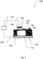
- Fig. 2 shows a section 200 of the device 100.
- the section 200 represents in particular a power supply 210 which provides an alternating voltage.
- the power supply 210 is connected to the building plate 120 via an electrical line 220 and to the metal plate 170 of the electrode 160 via a further electrical line 230, so that the alternating voltage can be applied between the electrode 160 and the building plate 120.
- the granular raw material 140 in the receptacle of the carrier formed by the carrier elements 130 and the building plate 120 can also be subjected to the alternating voltage.
- the electrical line 230 is designed such that it can also carry out the linear movement(s) of the electrode 160.
- the electrical contact between the voltage supply 210 and the electrode 160 thus exists throughout the entire linear movement(s) of the electrode 160, i.e. the electrode can be subjected to the alternating voltage at any time at which it carries out the linear movement(s).
- the electrical line 220 is designed in a similar way so that the building board 120 can also be subjected to the alternating voltage when it is moved to apply a new layer of the granular raw material 140.
- the electrical connection of the power supply 210 to the construction plate 120 or the electrode 160 can also be designed differently. It can be adapted in particular to the circumstances of the respective embodiment and/or the respective application.
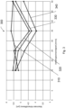
- Fig. 3 shows a diagram 300 with curves 310, 320, 330 and 340 of a maximum height difference.
- the curves 310, 320, 330 and 340 were determined using a profilometer and a reference system as follows.
- a reference carrier with a reference receptacle was provided that corresponded to the dimensions of the carrier and the receptacle of the carrier of the device 100.
- a reference voltage supply and a reference electrode were also added to the reference system.
- the reference voltage supply was designed in such a way that it could provide a reference alternating voltage with an effective value of 12 kV and a sinusoidal curve with a frequency of 50 Hz.
- the reference electrode was Furthermore, it was designed such that it could perform the same movements with respect to the reference holder and the reference carrier as the electrode 160 could perform with respect to the holder and the carrier of the device 100.
- the reference holder of the reference carrier was then filled with granular raw material 140, specifically with a titanium powder as granular raw material 140 and with the aid of a reference coater with a reference brush.
- the titanium powder also had a particle size distribution of 20 to 55 ⁇ m.
- a height profile of the granular raw material was recorded in the reference holder using the profilometer, specifically in an area that corresponds to the area of the holder of the carrier of the device 100 in which the component 110 is or would be located.
- the maximum height difference of the recorded height profile was determined as a measure of the irregularities and/or unevenness that arose when filling the reference holder with the reference coater. In this example, the maximum height difference of the recorded height profile was typically approximately 20 ⁇ m.
- the granular raw material 140 in the reference holder was then subjected to the reference alternating voltage and the reference electrode 160 was moved over the reference holder in a linear motion at a predetermined distance and a predetermined speed. At least part of the granular raw material 140 that was in the reference holder of the reference carrier was subjected to the reference alternating voltage and caused to oscillate and/or vibrate mechanically using the reference alternating voltage. In this way, the irregularities and/or unevenness of at least part of the granular raw material 140 that arose when the reference holder of the reference carrier was filled with the granular raw material were reduced or compensated for.
- the steps described above were repeated, whereby the specified distance and the specified speed were varied in each case.
- the reference electrode was moved at a specified distance of 0.5 mm over the reference recording, whereby the specified speed varied from 15 mm/s to 50 mm/s and was increased by 5 mm/s in each case.
- the curve 320 was carried out at the same specified speeds, but at a specified distance of 1 mm. At a distance of 2 mm resulted in the curve 340 and at a distance of 5 mm the curve 330.
- the curves 310, 320, 330 and 340 show that the irregularities and/or unevenness that arose when filling the reference holder with the reference coater could be significantly reduced or evened out.
- the value of the maximum height difference could be reduced by at least 70% in all cases.
- the reduction or evening out of the irregularities and/or unevenness can be optimized by choosing the correct specified distance and speed. In this example, the best result was achieved for a specified distance of 2 mm and a specified speed of 35 mm/s.
- Such measurement series can also be created using other reference systems and measuring equipment in order to optimize the specified speed and/or the specified distance.
- the measurement series can also be created using the recording of the carrier of the device 100.
- Fig. 4 shows a flow chart of an embodiment of a method 400 according to the invention for the additive production of a component 110 from granular raw material 140.
- the method is described by way of example with a titanium powder as the granular raw material 140.
- the titanium powder has a particle size distribution of 20 to 55 ⁇ m in order to Fig. 3
- the method is not limited to the processing of titanium powders and the particle size distribution mentioned. It is also suitable - as already sufficiently explained - for the processing of other granular raw materials, including those with other particle size distributions.
- the method begins with step 410, in which a device 100 and the granular raw material 140 are provided.
- step 420 the distance and the speed at which the electrode 160 is to be moved over the holder of the carrier are specified.
- the specified distance and the specified speed are selected in such a way as to optimize the removal and/or compensation of any irregularities and/or unevenness of at least part of the granular raw material located in the holder of the carrier of the device 100 by mechanical oscillations and/or vibrations generated using the alternating voltage and the electrode 160.
- the optimization is carried out using the Fig. 3 shown courses 310, 320, 330 and 340, ie the specified distance is 2 mm and the specified speed is 35 mm/s.
- step 430 the holder of the carrier is filled with a layer of the granular raw material 140 using the coater 150.
- the granular raw material 140 in the holder of the carrier is subjected to the alternating voltage using the electrode 160, whereby at least part of the granular raw material 140 with which the holder of the carrier is filled was set into mechanical oscillations and/or vibrations using the alternating voltage, and wherein any irregularities and/or unevenness of the at least part of the granular raw material 140 that arise when filling the holder of the carrier with the layer of the granular raw material 140 are reduced and/or compensated for using the mechanical oscillations and/or vibrations.
- the electrode 160 is moved over the holder of the carrier at the distance and at the speed that were specified in step 420.
- the component production unit 190 selectively solidifies the layer of the granular raw material in order to produce the component 110.
- Fig. 5 shows a section of a reference carrier 510 with a reference holder that is filled with granular raw material 140.
- the surface of the granular raw material 140 in the reference holder has pronounced orange peel effects.
- the orange peel effects are formed primarily by a large number of cracks 520 or a network of cracks 520.
- Fig. 5 was recorded after - as in connection with Fig. 3 described - the reference holder was filled with granular raw material and a reference electrode was moved over the reference holder, namely at a predetermined distance of 5 mm above the reference holder of the reference carrier 510 and at a predetermined speed of 15 mm/s.
- the cracks 520 are therefore not due to the filling of the reference holder of the reference carrier 510 with the granular raw material 140, but formed subsequently due to the application of the alternating voltage to the granular raw material 140 when the reference electrode was moved over the reference holder of the reference carrier 510.
- Fig. 6 shows a section of a reference carrier 610 with a reference holder.
- the reference holder of the reference carrier 610 is filled with granular raw material 140, the surface of which has virtually no orange peel effects.
- Fig. 6 was recorded in the same way as Fig. 5 However, the electrode was not moved over the reference holder 610 at a distance of 5 mm and at a speed of 15 mm/s, but at a predetermined distance of 2 mm and at a predetermined speed of 35 mm/s.
- Fig. 7 shows a stylized representation of the Fig. 5 section shown.
- Fig. 7 shows thus also a section of a reference carrier 710 with a reference holder that is filled with granular raw material 140.
- the surface of the granular raw material 140 in the reference holder has pronounced orange peel effects, which are formed by a large number of connected cracks 720.
- Fig. 7 are the cracks 720 compared to the cracks 520 in Fig. 5 enlarged. This also applies to the areas between the respective cracks.
- the cracks 720 are shown in black, while the cracks 520 in Fig. 5 are shown brighter than the areas enclosed by the cracks 520. The latter are in Fig. 7 shown in white. Effects at the edge of the reference image, which in Fig. 5 can be seen were in Fig. 7 omitted.
- the reference carrier 710 is also shown as a black frame.
- Fig. 8 shows similar to Figure 7 a stylized representation of the Fig. 6 section shown.
- Fig. 8 thus also shows a section of a reference carrier 810 with a reference holder which is filled with granular raw material 140.
- the surface of the granular raw material has, in contrast to the Fig. 7 In the situation shown, there is virtually no orange peel effect and therefore no cracks 720.
Landscapes
- Engineering & Computer Science (AREA)
- Chemical & Material Sciences (AREA)
- Manufacturing & Machinery (AREA)
- Materials Engineering (AREA)
- Automation & Control Theory (AREA)
- Physics & Mathematics (AREA)
- Plasma & Fusion (AREA)
- Jigging Conveyors (AREA)
Priority Applications (1)
| Application Number | Priority Date | Filing Date | Title |
|---|---|---|---|
| EP23170368.7A EP4454789A1 (fr) | 2023-04-27 | 2023-04-27 | Dispositif et procédé de fabrication additive d'un composant |
Applications Claiming Priority (1)
| Application Number | Priority Date | Filing Date | Title |
|---|---|---|---|
| EP23170368.7A EP4454789A1 (fr) | 2023-04-27 | 2023-04-27 | Dispositif et procédé de fabrication additive d'un composant |
Publications (1)
| Publication Number | Publication Date |
|---|---|
| EP4454789A1 true EP4454789A1 (fr) | 2024-10-30 |
Family
ID=86271764
Family Applications (1)
| Application Number | Title | Priority Date | Filing Date |
|---|---|---|---|
| EP23170368.7A Pending EP4454789A1 (fr) | 2023-04-27 | 2023-04-27 | Dispositif et procédé de fabrication additive d'un composant |
Country Status (1)
| Country | Link |
|---|---|
| EP (1) | EP4454789A1 (fr) |
Citations (11)
| Publication number | Priority date | Publication date | Assignee | Title |
|---|---|---|---|---|
| WO2009000360A1 (fr) | 2007-06-25 | 2008-12-31 | Eos Gmbh Electro Optical Systems | Dispositif servant à l'application de couches électrostatiques d'un matériau en poudre, et dispositif et procédé de production d'un objet à trois dimensions |
| WO2016205719A1 (fr) | 2015-06-19 | 2016-12-22 | Applied Materials, Inc. | Fabrication d'additifs au moyen de compactage électrostatique |
| US20180243768A1 (en) | 2017-02-24 | 2018-08-30 | Powder Motion Labs, LLC | Electrostatic powder feeder |
| WO2020260785A1 (fr) | 2019-06-27 | 2020-12-30 | Commissariat A L'energie Atomique Et Aux Energies Alternatives | Dispositif de fabrication additive et sa mise en oeuvre |
| US20210291446A1 (en) * | 2020-03-18 | 2021-09-23 | Powder Motion Labs, LLC | Powder bed recoater |
| US20210291445A1 (en) * | 2020-03-18 | 2021-09-23 | Powder Motion Labs, LLC | Powder bed recoater |
| US20210354202A1 (en) * | 2018-06-08 | 2021-11-18 | Hewlett-Packard Development Company, L.P. | Metal powder compactors |
| EP3943219A1 (fr) | 2020-07-24 | 2022-01-26 | Aixway3D GmbH | Dispositif et procédé d'application améliorée de poudre dans un procédé de fabrication additive |
| WO2022039720A1 (fr) * | 2020-08-18 | 2022-02-24 | Hewlett-Packard Development Company, L.P. | Champs électriques non uniformes pour compacter un matériau de fabrication métallique pulvérulent |
| US20220184709A1 (en) * | 2020-03-18 | 2022-06-16 | Powder Motion Labs, LLC | Powder Bed Recoater |
| CN115555585A (zh) | 2022-09-27 | 2023-01-03 | 重庆理工大学 | 一种用于粉末床熔融增材制造的非接触式铺粉装置及方法 |
-
2023
- 2023-04-27 EP EP23170368.7A patent/EP4454789A1/fr active Pending
Patent Citations (11)
| Publication number | Priority date | Publication date | Assignee | Title |
|---|---|---|---|---|
| WO2009000360A1 (fr) | 2007-06-25 | 2008-12-31 | Eos Gmbh Electro Optical Systems | Dispositif servant à l'application de couches électrostatiques d'un matériau en poudre, et dispositif et procédé de production d'un objet à trois dimensions |
| WO2016205719A1 (fr) | 2015-06-19 | 2016-12-22 | Applied Materials, Inc. | Fabrication d'additifs au moyen de compactage électrostatique |
| US20180243768A1 (en) | 2017-02-24 | 2018-08-30 | Powder Motion Labs, LLC | Electrostatic powder feeder |
| US20210354202A1 (en) * | 2018-06-08 | 2021-11-18 | Hewlett-Packard Development Company, L.P. | Metal powder compactors |
| WO2020260785A1 (fr) | 2019-06-27 | 2020-12-30 | Commissariat A L'energie Atomique Et Aux Energies Alternatives | Dispositif de fabrication additive et sa mise en oeuvre |
| US20210291446A1 (en) * | 2020-03-18 | 2021-09-23 | Powder Motion Labs, LLC | Powder bed recoater |
| US20210291445A1 (en) * | 2020-03-18 | 2021-09-23 | Powder Motion Labs, LLC | Powder bed recoater |
| US20220184709A1 (en) * | 2020-03-18 | 2022-06-16 | Powder Motion Labs, LLC | Powder Bed Recoater |
| EP3943219A1 (fr) | 2020-07-24 | 2022-01-26 | Aixway3D GmbH | Dispositif et procédé d'application améliorée de poudre dans un procédé de fabrication additive |
| WO2022039720A1 (fr) * | 2020-08-18 | 2022-02-24 | Hewlett-Packard Development Company, L.P. | Champs électriques non uniformes pour compacter un matériau de fabrication métallique pulvérulent |
| CN115555585A (zh) | 2022-09-27 | 2023-01-03 | 重庆理工大学 | 一种用于粉末床熔融增材制造的非接触式铺粉装置及方法 |
Similar Documents
| Publication | Publication Date | Title |
|---|---|---|
| EP1940575B1 (fr) | Procede de fabrication par couches avec commande de granulometrie | |
| EP2289462B1 (fr) | Dispositif et procédé de fabrication générative en continu | |
| EP1993812B1 (fr) | Procédé et dispositif de production d'un objet tridimensionnel | |
| DE102007006478B4 (de) | Vorrichtung und Verfahren zum Zuführen von sinterbarem Pulver auf eine Auftragsstelle einer Lasersintereinrichtung | |
| EP0738584A1 (fr) | Dispositif et procédé pour la fabrication d'un objet tridimensionnel | |
| EP3710182A1 (fr) | Éclairage sélectif par couche dans la zone en surplomb lors de la fabrication additive | |
| DE102015003372A1 (de) | Verfahren und Vorrichtung zum Herstellen von 3D-Formteilen mit Doppelrecoater | |
| DE102015206892A1 (de) | Verfahren zum Herstellen eines Bauteils durch thermisches Spritzen und Anlage zum Herstellen eines Bauteils mit einer Vorrichtung zum thermischen Spritzen | |
| DE102014204528A1 (de) | Verfahren und Vorrichtung zum selektiven Laserschmelzen | |
| WO2012152259A1 (fr) | Procédé de production, de réparation ou de remplacement d'un élément, avec solidification par sollicitation en compression | |
| EP3187328A1 (fr) | Procede et dispositif destines a la fabrication generative d'un objet tridimensionnel | |
| DE102015104827A1 (de) | Generatives Schichtaufbauverfahren und Vorrichtung zur Herstellung eines dreidimensionalen faserverstärkten Objekts | |
| DE102010045850A1 (de) | Verfahren und Vorrichtung zum generativen Herstellen eines Bauelementes | |
| EP3253514A1 (fr) | Procédé et dispositif de fabrication additive de pièces | |
| DE102018203151A1 (de) | Verfahren zur Herstellung von einem dreidimensionalen Bauteil | |
| DE102010046580A1 (de) | Vorrichtung zum Herstellen, Reparieren und/oder Austauschen eines Bauteils mittels eines durch Energiestrahlung verfestigbaren Pulvers, sowie ein Verfahren und ein gemäß dem Verfahren hergestellten Bauteils | |
| EP3386661A1 (fr) | Dispositif et procédé de fabrication d'un corps moulé métallique tridimensionnel | |
| EP4454789A1 (fr) | Dispositif et procédé de fabrication additive d'un composant | |
| DE102018122296A1 (de) | Verfahren und Einrichtung zur additiven Fertigung eines Bauteils mit einer Stützstruktur | |
| WO2021078316A1 (fr) | Système et procédé de génération d'une couche d'un matériau de construction particulaire dans une imprimante 3d | |
| EP3697598A2 (fr) | Procédé de fabrication additive d'un composant et dispositif pour la mise en uvre du procédé | |
| EP4584037A1 (fr) | Procédé et dispositif de production de micro-éléments et de micro-composants par fabrication additive par micro-fusion laser | |
| WO2022268245A1 (fr) | Procédé et dispositif de production de moulages 3d par stratification, faisant appel à une coucheuse à lame conique | |
| DE102014218297B4 (de) | Gießform, Gießformsystem und Verfahren zur Herstellung einer Formhaut | |
| WO2019011532A1 (fr) | Procédé d'impression 3d et dispositif d'impression 3d |
Legal Events
| Date | Code | Title | Description |
|---|---|---|---|
| PUAI | Public reference made under article 153(3) epc to a published international application that has entered the european phase |
Free format text: ORIGINAL CODE: 0009012 |
|
| STAA | Information on the status of an ep patent application or granted ep patent |
Free format text: STATUS: THE APPLICATION HAS BEEN PUBLISHED |
|
| AK | Designated contracting states |
Kind code of ref document: A1 Designated state(s): AL AT BE BG CH CY CZ DE DK EE ES FI FR GB GR HR HU IE IS IT LI LT LU LV MC ME MK MT NL NO PL PT RO RS SE SI SK SM TR |
|
| STAA | Information on the status of an ep patent application or granted ep patent |
Free format text: STATUS: REQUEST FOR EXAMINATION WAS MADE |
|
| 17P | Request for examination filed |
Effective date: 20250416 |