EP4454837A1 - Dispositif de préhension - Google Patents
Dispositif de préhension Download PDFInfo
- Publication number
- EP4454837A1 EP4454837A1 EP22910534.1A EP22910534A EP4454837A1 EP 4454837 A1 EP4454837 A1 EP 4454837A1 EP 22910534 A EP22910534 A EP 22910534A EP 4454837 A1 EP4454837 A1 EP 4454837A1
- Authority
- EP
- European Patent Office
- Prior art keywords
- fluid pressure
- grasping device
- pressure actuator
- actuator
- partition plate
- Prior art date
- Legal status (The legal status is an assumption and is not a legal conclusion. Google has not performed a legal analysis and makes no representation as to the accuracy of the status listed.)
- Pending
Links
Images



Classifications
-
- B—PERFORMING OPERATIONS; TRANSPORTING
- B25—HAND TOOLS; PORTABLE POWER-DRIVEN TOOLS; MANIPULATORS
- B25J—MANIPULATORS; CHAMBERS PROVIDED WITH MANIPULATION DEVICES
- B25J15/00—Gripping heads and other end effectors
-
- B—PERFORMING OPERATIONS; TRANSPORTING
- B25—HAND TOOLS; PORTABLE POWER-DRIVEN TOOLS; MANIPULATORS
- B25J—MANIPULATORS; CHAMBERS PROVIDED WITH MANIPULATION DEVICES
- B25J15/00—Gripping heads and other end effectors
- B25J15/0023—Gripper surfaces directly activated by a fluid
-
- B—PERFORMING OPERATIONS; TRANSPORTING
- B25—HAND TOOLS; PORTABLE POWER-DRIVEN TOOLS; MANIPULATORS
- B25J—MANIPULATORS; CHAMBERS PROVIDED WITH MANIPULATION DEVICES
- B25J15/00—Gripping heads and other end effectors
- B25J15/08—Gripping heads and other end effectors having finger members
-
- B—PERFORMING OPERATIONS; TRANSPORTING
- B25—HAND TOOLS; PORTABLE POWER-DRIVEN TOOLS; MANIPULATORS
- B25J—MANIPULATORS; CHAMBERS PROVIDED WITH MANIPULATION DEVICES
- B25J15/00—Gripping heads and other end effectors
- B25J15/08—Gripping heads and other end effectors having finger members
- B25J15/10—Gripping heads and other end effectors having finger members with three or more finger members
-
- B—PERFORMING OPERATIONS; TRANSPORTING
- B25—HAND TOOLS; PORTABLE POWER-DRIVEN TOOLS; MANIPULATORS
- B25J—MANIPULATORS; CHAMBERS PROVIDED WITH MANIPULATION DEVICES
- B25J15/00—Gripping heads and other end effectors
- B25J15/08—Gripping heads and other end effectors having finger members
- B25J15/12—Gripping heads and other end effectors having finger members with flexible finger members
-
- B—PERFORMING OPERATIONS; TRANSPORTING
- B25—HAND TOOLS; PORTABLE POWER-DRIVEN TOOLS; MANIPULATORS
- B25J—MANIPULATORS; CHAMBERS PROVIDED WITH MANIPULATION DEVICES
- B25J19/00—Accessories fitted to manipulators, e.g. for monitoring, for viewing; Safety devices combined with or specially adapted for use in connection with manipulators
-
- F—MECHANICAL ENGINEERING; LIGHTING; HEATING; WEAPONS; BLASTING
- F15—FLUID-PRESSURE ACTUATORS; HYDRAULICS OR PNEUMATICS IN GENERAL
- F15B—SYSTEMS ACTING BY MEANS OF FLUIDS IN GENERAL; FLUID-PRESSURE ACTUATORS, e.g. SERVOMOTORS; DETAILS OF FLUID-PRESSURE SYSTEMS, NOT OTHERWISE PROVIDED FOR
- F15B15/00—Fluid-actuated devices for displacing a member from one position to another; Gearing associated therewith
- F15B15/08—Characterised by the construction of the motor unit
- F15B15/10—Characterised by the construction of the motor unit the motor being of diaphragm type
Definitions
- the present disclosure relates to a grasping device using a fluid pressure actuator that curves (curls) during contraction.
- McKibben type a structure having a rubber tube that expands and contracts by air pressure and a sleeve that covers the outer peripheral surface of the tube has been widely used as a fluid pressure actuator that expands and contracts the tube using a gas or liquid.
- Patent Literature 1 discloses a grasping device for grasping an object (which may be called a workpiece) by using a plurality of such fluid pressure actuators.
- Patent Literature 1 Japanese Patent Laid-Open No. 2021-088999
- the above-described grasping device using a fluid pressure actuator has the following problems. Specifically, it is difficult to grasp an appropriate amount of an object at one time, and the amount of an object that can be grasped becomes large or small.
- the following disclosure is made in view of such a situation, and it is an object to provide a grasping device that can grasp an appropriate amount of an object at each time while using a fluid pressure actuator that curves (curls) during contraction.
- An embodiment of the present disclosure is a grasping device (For example, grasping device 1) using a plurality of fluid pressure actuators (fluid pressure actuator 10) that are curved during contraction.
- the fluid pressure actuators include a tube (tube 110) that is cylindrical, and expands and contracts under fluid pressure, and a sleeve (sleeve 120) having a stretchable structure in which fiber cords oriented in a predetermined direction are woven and that covers an outer peripheral surface of the tube.
- a spoon-shaped housing portion (housing portion 50) is provided at a tip portion (tip portion 300) of each of the fluid pressure actuators, and a partition plate (partition plate 30) is provided to close an opening surface (opening surface 50a) of the housing portion when the fluid pressure actuator is non-curved or curved.
- an appropriate amount of an object can be grasped each time while using a fluid pressure actuator that curves (curls) during contraction.
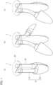
- FIGS. 1 (a), 1 (b) and 1 (c) are perspective views of the grasping device 1 according to the present embodiment. Specifically, FIG. 1 (a) is a perspective view of the grasping device 1 when the fluid pressure actuator 10 is non-curved. FIG. 1 (b) is a perspective view of the grasping device 1 when the fluid pressure actuator 10 is curved. FIG. 1 (c) is a perspective view of the grasping device 1 when one of the fluid pressure actuators 10 is curved.
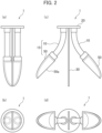
- FIGS. 2 (a) to 2 (d) are side views and bottom views of the grasping device 1. Specifically, FIGS. 2 (a) and 2 (b) show a side view and a bottom view of the grasping device 1 (when the fluid pressure actuator 10 is non-curved (non-contracted)), respectively. FIGS. 2 (c) and 2 (d) show a side view and a bottom view of the grasping device 1 (when the fluid pressure actuator 10 is curved (contracted)), respectively.
- the grasping device 1 uses a plurality of fluid pressure actuators 10 (soft actuators that can be curved and have flexibility) that curve (curl) during contraction.
- the grasping device 1 can grasp an object (which may be called a workpiece) using a plurality of fluid pressure actuators 10.
- the grasping device 1 may be used as a robot hand or the like.
- the grasping device 1 includes a shovel unit 15, a mounting base 20 and a partition plate 30.
- the shovel unit 15 is configured by a fluid pressure actuator 10 and a housing portion 50.
- the fluid pressure actuator 10 is mounted on the mounting base 20. Specifically, the proximal end portion 200 (Not shown in FIGS 1 and 2 , see FIG 3 ) of the fluid pressure actuator 10 is mounted on the mounting base 20.
- a tip portion 300 (see FIG. 3 ) of the fluid pressure actuator 10 is provided with the spoon-shaped housing portion 50.
- the housing portion 50 is concave to hold the scooped object by operating (contracting and expanding) the fluid pressure actuator 10.
- the shovel unit 15 including the housing portion 50 may be referred to in other similar terms such as cup, bucket, etc.
- the partition plate 30 is provided to partition the plurality of shovel units 15. Specifically, the partition plate 30 has a flat plate shape and is provided between the two shovel units 15. That is, the fluid pressure actuator 10 (shovel unit 15) may be provided on both sides of the partition plate 30.
- the partition plate 30 is provided so as to close an opening surface 50a of the housing portion 50 when the fluid pressure actuator 10 is non-curved (non-contracted).
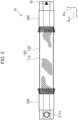
- FIG. 3 is a side view of the fluid pressure actuator 10 according to the present embodiment.
- FIG. 4 is a cross-sectional view of the actuator body portion 100 along the radial direction D R .
- the fluid pressure actuator 10 has the actuator body portion 100, the proximal end portion 200 and the tip portion 300.
- the actuator body portion 100 is composed of a tube 110 and a sleeve 120. Fluid flows into the actuator body portion 100 through a connection port 211a.
- the actuator body portion 100 contracts in the axial direction D AX of the actuator body portion 100 and expands in the radial direction D R due to fluid flow into the tube 110.
- the actuator body portion 100 expands in the axial direction D AX of the actuator body portion 100 and contracts in the radial direction D R due to fluid flow out of the tube 110. Due to the shape change of the actuator body portion 100, the fluid pressure actuator 10 functions as an actuator.
- the fluid used to drive the fluid pressure actuator 10 may be either a gas such as air or a liquid such as water or mineral oil, but in particular, the fluid pressure actuator 10 may have high durability that can withstand hydraulic drive with high pressure applied to the actuator body portion 100.
- connection port 211a is attached to a drive pressure source for the fluid pressure actuator 10, specifically a hose (pipeline) connected to a gas or liquid compressor.
- the fluid that flows through the connection port 211a flows through the passage hole (not shown) into the actuator body portion 100, specifically into the tube 110.
- the tube 110 is a cylindrical body that expands and contracts under fluid pressure.
- the tube 110 is made of an elastic material such as butyl rubber to repeatedly contract and expand under fluid pressure.
- the fluid pressure actuator 10 is hydraulically driven, it is preferable that it be at least one type selected from the group consisting of NBR (nitrile rubber), chloroprene rubber, and epichlorohydrin rubber having high oil resistance.
- the sleeve 120 is cylindrical and covers the outer peripheral surface of the tube 110.
- the sleeve 120 is a stretchable structure in which fiber cords oriented in a predetermined direction are woven, and a rhombic shape is repeated by crossing the oriented cords. By having such a shape, the sleeve 120 deforms pantographically and follows the tube 110 while restricting its contraction and expansion.
- a fiber cord of an aromatic polyamide (aramid fiber) or polyethylene terephthalate (PET) is preferably used.
- aromatic polyamide aromatic polyamide
- PET polyethylene terephthalate
- the restricting member 150 is provided between the tube 110 and the sleeve 120.
- the restricting member 150 is not compressed in the axial direction D AX , and can be deformed only along the radial direction D R (which may be called the deflection direction). That is, the restricting member 150 resists compression along the axial direction D AX and is deformable in an orthogonal direction (radial direction D R ) orthogonal to the axial direction D AX .
- the restricting member 150 has a characteristic that is difficult to deform along the axial direction D AX and deflects along the radial direction D R .
- Deformable may be alternatively referred to as curving or curling.
- the restricting member 150 also has a function of restricting (restraining) the expansion of the tube 110 (and the sleeve 120) to the radial direction D R outside at a position on the outer periphery of the tube 110 where the restricting member 150 is provided.
- the restricting member 150 is provided from one end side to the other end side of the axial direction D AX in the space of inside of the sleeve 120, specifically, the radial inside of the sleeve 120.
- the restricting member 150 is formed by using a leaf spring.
- the size of the leaf spring may be selected according to the size of the fluid pressure actuator 10, the required generating force, etc., and is not particularly limited.
- the material of the leaf spring is also not particularly limited, but typically it may be a material that is easy to curve and resistant to compression, such as a metal such as stainless steel.
- the restricting member 150 may be formed of a thin sheet of carbon fiber reinforced plastic (CFRP) or the like. Since the CFRP is less likely to undergo plastic deformation than a metal, it is easy for the fluid pressure actuator 10 to return to its original straight state after curving.
- CFRP carbon fiber reinforced plastic
- the proximal end portion 200 is located on the base portion 20 side.
- the connection port 211a described above is formed on the proximal end portion 200.
- the proximal end portion 200 may include a mechanism for sealing one end portion of the axial direction D AX of the actuator body portion 100.
- the tip portion 300 is located on the opposite side of the proximal end portion 200 on the base portion 20 side.
- the tip portion 300 may be provided with a mechanism for sealing the other end portion of the axial direction D AX of the actuator body portion 100.
- the sealing mechanism of the actuator body portion 100 provided in the proximal end portion 200 and the tip portion 300 may be similar to, for example, the fluid pressure actuator disclosed in Japanese Patent Laid-Open Publication No. 2021-088999 .
- FIG. 5 is an explanatory view of the behavior of the fluid pressure actuator 10.
- the fluid pressure actuator 10 shown in FIG. 5 is fixed to the proximal end portion 200 side, and the tip portion 300 side is freely movable. That is, the proximal end portion 200 side is a fixed end, and the tip portion 300 side is a free end.
- the restricting member 150 formed by a rigid member such as a leaf spring serves as a backbone, and expands in the radial direction D R outside on the opposite side (lower side in FIG. 5 ) to the position on the outer periphery of the tube 110 and sleeve 120 where the restricting member 150 is provided, thereby shortening the dimension of the fluid pressure actuator 10 in the axial direction D AX and deflecting the fluid pressure actuator 10 (Specifically, the actuator body portion 100) along the direction D1.
- the direction D1 may be called a flexible direction.
- a mark M may be provided to indicate the position where the restricting member 150 is provided.
- the restricting member 150 is provided between the rubber made tube 110 and the sleeve 120, resists compression in the axial direction D AX , is deformable along the orthogonal direction (radial direction D R ) orthogonal to, and is arranged in a part in the circumferential direction of the actuator body portion 100.
- FIGS. 6 (a), (b) and 6 (c) show an example of operation of the grasping device 1. Specifically, FIGS. 6 (a), (b) and 6 (c) show an example of operation in which the grasping device 1 scoops up a granular object W. As shown in FIGS. 6 (a), (b) and 6 (c) , the grasping device 1 functions as a robotic hand and may be movably supported by a support portion.
- a space is formed between the partition plate 30 and the housing portion 50 (Specifically, the opening surface 50a) by contracting and curving the fluid pressure actuator 10.
- the grasping device 1 is moved to a desired position so that the object W can be scooped.
- the movement of the grasping device 1 may be performed manually or by a mechanical method.
- the object W is not particularly limited, for example, the grasping device 1 can be suitably used for serving various foodstuffs included in a lunch box.
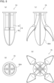
- FIGS. 7 (a), (b) and (c) are perspective views of the grasping device 1A related to modified example. Specifically, FIG. 7 (a) is a perspective view of the grasping device 1A when the fluid pressure actuator 10 is not contracted. FIG. 7 (b) is a perspective view of the grasping device 1A when the fluid pressure actuator 10 is contracted. FIG. 7 (c) is a perspective view of the grasping device 1A when a part of the fluid pressure actuator 10 is contracted.
- FIGS. 8 (a) to (d) are side views and bottom views of the grasping device 1A. Specifically, FIGS. 8 (a) and 8 (b) show a side view and a bottom view of the grasping device 1A (when the fluid pressure actuator 10 is not contracted), respectively. FIGS. 8 (c) and 8 (d) show a side view and a bottom view of the grasping device 1A (when the fluid pressure actuator 10 is contracted), respectively.
- the partition plate 30 A has a cross shape in the bottom view of the grasping device 1A.
- Four shovel units 15 composed of a fluid pressure actuator 10 and a housing portion 50 are provided.
- the fluid pressure actuator 10 (shovel unit 15) is provided in each of four spaces partitioned by a partition plate 30 A.
- the partition plate may not have a cross shape, but may form a plurality of spaces (For example, three or five), and the fluid pressure actuator 10 may be provided in each of the plurality of spaces partitioned by the partition plate.
- Each of the fluid pressure actuators 10 can operate (contract and expand) individually. Therefore, the grasping device 1A can handle a larger amount of the object W of a predetermined unit amount in one operation cycle (from scooping to releasing the object W) compared with the grasping device 1. Specifically, the grasping device 1 can handle two units of the object W because it has two shovel units 15, while the grasping device 1A can handle four units of the object W because it has four shovel units 15.
- the tip portion 300 of the fluid pressure actuator 10 is provided with the spoon-shaped housing portion 50, and the partition plate 30 for closing the opening surface 50a of the housing portion 50 when the fluid pressure actuator 10 is non-curved (non-contracted).
- the scooped object W does not spill out, and the object W to be determined is generally held in the housing portion 50. That is, the shovel unit 15 can more reliably grasp (hold) an appropriate amount of the object W at a time.
- the grasping device 1 (and the grasping device 1A) can grasp (hold) an appropriate amount of the object at each time while using a fluid pressure actuator that curves (curls) during contraction.
- the fluid pressure actuator 10 (shovel unit 15) may be provided on both sides of the partition plate 30. Therefore, in one operation cycle (from the scooping up to the releasing the object W), a predetermined unit amount of the object W can be handled more.
- the partition plate 30 A has a cross shape in the bottom view of the grasping device 1A, and four shovel units 15 are provided. Therefore, a predetermined unit amount of the object W can be handled more in one operation cycle (from scooping to releasing the object W).
- an additional partition plate may be provided on the upper surface side of the housing portion 50 to make the amount of the object W held by the housing portion 50 more accurate.
- the partition plate 30 may be provided to close the opening surface 50a of the housing portion 50 when the fluid pressure actuator 10 is non-curved (non-contracted), but may close the opening surface 50a of the housing portion 50 when the fluid pressure actuator 10 is curved.
- shovel unit 15 In the grasping device 1 and the grasping device 1A, a plurality of shovel units 15 are provided, but the shovel unit 15 may be one.
- the flexibility of the fluid pressure actuator is ensured using the restricting member 150, but the flexibility of the fluid pressure actuator may be ensured by another structure.
- the fluid pressure actuator when the fluid pressure actuator contracts, the fluid pressure actuator is curved such that the bellows portion faces toward an inside.
Landscapes
- Engineering & Computer Science (AREA)
- Mechanical Engineering (AREA)
- Robotics (AREA)
- Physics & Mathematics (AREA)
- Fluid Mechanics (AREA)
- General Engineering & Computer Science (AREA)
- Manipulator (AREA)
- Actuator (AREA)
Applications Claiming Priority (2)
| Application Number | Priority Date | Filing Date | Title |
|---|---|---|---|
| JP2021206027A JP7611808B2 (ja) | 2021-12-20 | 2021-12-20 | 把持装置 |
| PCT/JP2022/038505 WO2023119808A1 (fr) | 2021-12-20 | 2022-10-17 | Dispositif de préhension |
Publications (2)
| Publication Number | Publication Date |
|---|---|
| EP4454837A1 true EP4454837A1 (fr) | 2024-10-30 |
| EP4454837A4 EP4454837A4 (fr) | 2025-03-12 |
Family
ID=86901970
Family Applications (1)
| Application Number | Title | Priority Date | Filing Date |
|---|---|---|---|
| EP22910534.1A Pending EP4454837A4 (fr) | 2021-12-20 | 2022-10-17 | Dispositif de préhension |
Country Status (5)
| Country | Link |
|---|---|
| US (1) | US20250050513A1 (fr) |
| EP (1) | EP4454837A4 (fr) |
| JP (1) | JP7611808B2 (fr) |
| CN (1) | CN118382517A (fr) |
| WO (1) | WO2023119808A1 (fr) |
Family Cites Families (10)
| Publication number | Priority date | Publication date | Assignee | Title |
|---|---|---|---|---|
| JPH09109077A (ja) * | 1995-10-12 | 1997-04-28 | Kubota Corp | ロボットハンド用指 |
| JPH09109078A (ja) * | 1995-10-12 | 1997-04-28 | Kubota Corp | ロボットハンド |
| JP4647856B2 (ja) | 2001-08-30 | 2011-03-09 | セコム株式会社 | 食事支援装置 |
| US10974382B2 (en) * | 2014-06-09 | 2021-04-13 | Soft Robotics Inc. | Soft robotic actuators utilizing asymmetric surfaces |
| JP6951106B2 (ja) | 2017-04-14 | 2021-10-20 | 川崎重工業株式会社 | 食品保持装置およびその動作方法 |
| WO2018204275A1 (fr) * | 2017-05-01 | 2018-11-08 | Soft Robotics, Inc. | Structure pour effecteur terminal robotique |
| JP7002217B2 (ja) | 2017-05-15 | 2022-01-20 | 株式会社前川製作所 | 食品把持装置、食品移載装置及び食品把持方法 |
| JP2021088999A (ja) | 2019-12-02 | 2021-06-10 | 株式会社ブリヂストン | 流体圧アクチュエータ |
| WO2021256996A1 (fr) | 2020-06-17 | 2021-12-23 | National University Of Singapore | Organe de préhension robotique |
| CN112720513A (zh) | 2020-12-17 | 2021-04-30 | 山东得知科技发展有限公司 | 一种药材精准抓取装置及抓药方法 |
-
2021
- 2021-12-20 JP JP2021206027A patent/JP7611808B2/ja active Active
-
2022
- 2022-10-17 CN CN202280082404.2A patent/CN118382517A/zh active Pending
- 2022-10-17 US US18/721,385 patent/US20250050513A1/en active Pending
- 2022-10-17 WO PCT/JP2022/038505 patent/WO2023119808A1/fr not_active Ceased
- 2022-10-17 EP EP22910534.1A patent/EP4454837A4/fr active Pending
Also Published As
| Publication number | Publication date |
|---|---|
| JP2023091339A (ja) | 2023-06-30 |
| JP7611808B2 (ja) | 2025-01-10 |
| WO2023119808A1 (fr) | 2023-06-29 |
| EP4454837A4 (fr) | 2025-03-12 |
| US20250050513A1 (en) | 2025-02-13 |
| CN118382517A (zh) | 2024-07-23 |
Similar Documents
| Publication | Publication Date | Title |
|---|---|---|
| JP2021088999A (ja) | 流体圧アクチュエータ | |
| Daerden et al. | Pneumatic artificial muscles: actuators for robotics and automation | |
| EP4455490A1 (fr) | Dispositif de préhension | |
| EP4454837A1 (fr) | Dispositif de préhension | |
| JP7349338B2 (ja) | 流体圧アクチュエータ | |
| JP2023131050A (ja) | ロボットハンド | |
| JP2010127429A (ja) | 流体アクチュエータ | |
| EP4450831A1 (fr) | Dispositif de préhension | |
| EP4491884A1 (fr) | Actionneur hydraulique | |
| EP4491885A1 (fr) | Actionneur par pression de fluide avec élément de recouvrement | |
| EP4450832A1 (fr) | Dispositif de préhension | |
| WO2023171113A1 (fr) | Main de robot | |
| CN118355198A (zh) | 流体压驱动器 | |
| WO2023112446A1 (fr) | Actionneur hydraulique | |
| JP2023091136A (ja) | 把持装置 | |
| JP2024039553A (ja) | ロボットハンド | |
| Ranzani et al. | Design of the Multi-module Manipulator | |
| CN118234958A (zh) | 带致动器罩的保持构件和致动器罩 |
Legal Events
| Date | Code | Title | Description |
|---|---|---|---|
| STAA | Information on the status of an ep patent application or granted ep patent |
Free format text: STATUS: THE INTERNATIONAL PUBLICATION HAS BEEN MADE |
|
| PUAI | Public reference made under article 153(3) epc to a published international application that has entered the european phase |
Free format text: ORIGINAL CODE: 0009012 |
|
| STAA | Information on the status of an ep patent application or granted ep patent |
Free format text: STATUS: REQUEST FOR EXAMINATION WAS MADE |
|
| 17P | Request for examination filed |
Effective date: 20240613 |
|
| AK | Designated contracting states |
Kind code of ref document: A1 Designated state(s): AL AT BE BG CH CY CZ DE DK EE ES FI FR GB GR HR HU IE IS IT LI LT LU LV MC ME MK MT NL NO PL PT RO RS SE SI SK SM TR |
|
| A4 | Supplementary search report drawn up and despatched |
Effective date: 20250212 |
|
| RIC1 | Information provided on ipc code assigned before grant |
Ipc: F15B 15/10 20060101ALI20250206BHEP Ipc: B25J 19/00 20060101ALI20250206BHEP Ipc: B25J 15/10 20060101ALI20250206BHEP Ipc: B25J 15/08 20060101ALI20250206BHEP Ipc: B25J 15/00 20060101ALI20250206BHEP Ipc: B25J 15/12 20060101AFI20250206BHEP |
|
| DAV | Request for validation of the european patent (deleted) | ||
| DAX | Request for extension of the european patent (deleted) | ||
| STAA | Information on the status of an ep patent application or granted ep patent |
Free format text: STATUS: EXAMINATION IS IN PROGRESS |
|
| 17Q | First examination report despatched |
Effective date: 20250717 |