EP4454867A1 - Befestigungsklammer, befestigungskit, aircra. struktur und verfahren - Google Patents
Befestigungsklammer, befestigungskit, aircra. struktur und verfahren Download PDFInfo
- Publication number
- EP4454867A1 EP4454867A1 EP23170478.4A EP23170478A EP4454867A1 EP 4454867 A1 EP4454867 A1 EP 4454867A1 EP 23170478 A EP23170478 A EP 23170478A EP 4454867 A1 EP4454867 A1 EP 4454867A1
- Authority
- EP
- European Patent Office
- Prior art keywords
- fastener
- pins
- holding structure
- bracket
- fastener bracket
- Prior art date
- Legal status (The legal status is an assumption and is not a legal conclusion. Google has not performed a legal analysis and makes no representation as to the accuracy of the status listed.)
- Pending
Links
Images


Classifications
-
- F—MECHANICAL ENGINEERING; LIGHTING; HEATING; WEAPONS; BLASTING
- F16—ENGINEERING ELEMENTS AND UNITS; GENERAL MEASURES FOR PRODUCING AND MAINTAINING EFFECTIVE FUNCTIONING OF MACHINES OR INSTALLATIONS; THERMAL INSULATION IN GENERAL
- F16B—DEVICES FOR FASTENING OR SECURING CONSTRUCTIONAL ELEMENTS OR MACHINE PARTS TOGETHER, e.g. NAILS, BOLTS, CIRCLIPS, CLAMPS, CLIPS OR WEDGES; JOINTS OR JOINTING
- F16B19/00—Bolts without screw-thread; Pins, including deformable elements; Rivets
- F16B19/04—Rivets; Spigots or the like fastened by riveting
- F16B19/06—Solid rivets made in one piece
-
- B—PERFORMING OPERATIONS; TRANSPORTING
- B64—AIRCRAFT; AVIATION; COSMONAUTICS
- B64C—AEROPLANES; HELICOPTERS
- B64C1/00—Fuselages; Constructional features common to fuselages, wings, stabilising surfaces or the like
- B64C1/06—Frames; Stringers; Longerons ; Fuselage sections
- B64C1/061—Frames
-
- B—PERFORMING OPERATIONS; TRANSPORTING
- B64—AIRCRAFT; AVIATION; COSMONAUTICS
- B64C—AEROPLANES; HELICOPTERS
- B64C1/00—Fuselages; Constructional features common to fuselages, wings, stabilising surfaces or the like
- B64C1/06—Frames; Stringers; Longerons ; Fuselage sections
- B64C1/064—Stringers; Longerons
-
- B—PERFORMING OPERATIONS; TRANSPORTING
- B64—AIRCRAFT; AVIATION; COSMONAUTICS
- B64C—AEROPLANES; HELICOPTERS
- B64C1/00—Fuselages; Constructional features common to fuselages, wings, stabilising surfaces or the like
- B64C1/06—Frames; Stringers; Longerons ; Fuselage sections
- B64C1/068—Fuselage sections
-
- B—PERFORMING OPERATIONS; TRANSPORTING
- B64—AIRCRAFT; AVIATION; COSMONAUTICS
- B64C—AEROPLANES; HELICOPTERS
- B64C3/00—Wings
- B64C3/18—Spars; Ribs; Stringers
- B64C3/187—Ribs
-
- F—MECHANICAL ENGINEERING; LIGHTING; HEATING; WEAPONS; BLASTING
- F16—ENGINEERING ELEMENTS AND UNITS; GENERAL MEASURES FOR PRODUCING AND MAINTAINING EFFECTIVE FUNCTIONING OF MACHINES OR INSTALLATIONS; THERMAL INSULATION IN GENERAL
- F16B—DEVICES FOR FASTENING OR SECURING CONSTRUCTIONAL ELEMENTS OR MACHINE PARTS TOGETHER, e.g. NAILS, BOLTS, CIRCLIPS, CLAMPS, CLIPS OR WEDGES; JOINTS OR JOINTING
- F16B19/00—Bolts without screw-thread; Pins, including deformable elements; Rivets
- F16B19/04—Rivets; Spigots or the like fastened by riveting
- F16B19/08—Hollow rivets; Multi-part rivets
- F16B19/10—Hollow rivets; Multi-part rivets fastened by expanding mechanically
- F16B19/1027—Multi-part rivets
-
- F—MECHANICAL ENGINEERING; LIGHTING; HEATING; WEAPONS; BLASTING
- F16—ENGINEERING ELEMENTS AND UNITS; GENERAL MEASURES FOR PRODUCING AND MAINTAINING EFFECTIVE FUNCTIONING OF MACHINES OR INSTALLATIONS; THERMAL INSULATION IN GENERAL
- F16B—DEVICES FOR FASTENING OR SECURING CONSTRUCTIONAL ELEMENTS OR MACHINE PARTS TOGETHER, e.g. NAILS, BOLTS, CIRCLIPS, CLAMPS, CLIPS OR WEDGES; JOINTS OR JOINTING
- F16B5/00—Joining sheets or plates, e.g. panels, to one another or to strips or bars parallel to them
- F16B5/04—Joining sheets or plates, e.g. panels, to one another or to strips or bars parallel to them by means of riveting
-
- B—PERFORMING OPERATIONS; TRANSPORTING
- B29—WORKING OF PLASTICS; WORKING OF SUBSTANCES IN A PLASTIC STATE IN GENERAL
- B29C—SHAPING OR JOINING OF PLASTICS; SHAPING OF MATERIAL IN A PLASTIC STATE, NOT OTHERWISE PROVIDED FOR; AFTER-TREATMENT OF THE SHAPED PRODUCTS, e.g. REPAIRING
- B29C65/00—Joining or sealing of preformed parts, e.g. welding of plastics materials; Apparatus therefor
- B29C65/56—Joining or sealing of preformed parts, e.g. welding of plastics materials; Apparatus therefor using mechanical means or mechanical connections, e.g. form-fits
- B29C65/60—Riveting or staking
- B29C65/601—Riveting or staking using extra riveting elements, i.e. the rivets being non-integral with the parts to be joined
-
- B—PERFORMING OPERATIONS; TRANSPORTING
- B29—WORKING OF PLASTICS; WORKING OF SUBSTANCES IN A PLASTIC STATE IN GENERAL
- B29C—SHAPING OR JOINING OF PLASTICS; SHAPING OF MATERIAL IN A PLASTIC STATE, NOT OTHERWISE PROVIDED FOR; AFTER-TREATMENT OF THE SHAPED PRODUCTS, e.g. REPAIRING
- B29C65/00—Joining or sealing of preformed parts, e.g. welding of plastics materials; Apparatus therefor
- B29C65/56—Joining or sealing of preformed parts, e.g. welding of plastics materials; Apparatus therefor using mechanical means or mechanical connections, e.g. form-fits
- B29C65/60—Riveting or staking
- B29C65/606—Riveting or staking the rivets being integral with one of the parts to be joined, i.e. staking
-
- B—PERFORMING OPERATIONS; TRANSPORTING
- B29—WORKING OF PLASTICS; WORKING OF SUBSTANCES IN A PLASTIC STATE IN GENERAL
- B29C—SHAPING OR JOINING OF PLASTICS; SHAPING OF MATERIAL IN A PLASTIC STATE, NOT OTHERWISE PROVIDED FOR; AFTER-TREATMENT OF THE SHAPED PRODUCTS, e.g. REPAIRING
- B29C66/00—General aspects of processes or apparatus for joining preformed parts
- B29C66/01—General aspects dealing with the joint area or with the area to be joined
- B29C66/05—Particular design of joint configurations
- B29C66/10—Particular design of joint configurations particular design of the joint cross-sections
- B29C66/11—Joint cross-sections comprising a single joint-segment, i.e. one of the parts to be joined comprising a single joint-segment in the joint cross-section
- B29C66/112—Single lapped joints
-
- B—PERFORMING OPERATIONS; TRANSPORTING
- B29—WORKING OF PLASTICS; WORKING OF SUBSTANCES IN A PLASTIC STATE IN GENERAL
- B29C—SHAPING OR JOINING OF PLASTICS; SHAPING OF MATERIAL IN A PLASTIC STATE, NOT OTHERWISE PROVIDED FOR; AFTER-TREATMENT OF THE SHAPED PRODUCTS, e.g. REPAIRING
- B29C66/00—General aspects of processes or apparatus for joining preformed parts
- B29C66/01—General aspects dealing with the joint area or with the area to be joined
- B29C66/05—Particular design of joint configurations
- B29C66/10—Particular design of joint configurations particular design of the joint cross-sections
- B29C66/13—Single flanged joints; Fin-type joints; Single hem joints; Edge joints; Interpenetrating fingered joints; Other specific particular designs of joint cross-sections not provided for in groups B29C66/11 - B29C66/12
- B29C66/131—Single flanged joints, i.e. one of the parts to be joined being rigid and flanged in the joint area
-
- B—PERFORMING OPERATIONS; TRANSPORTING
- B29—WORKING OF PLASTICS; WORKING OF SUBSTANCES IN A PLASTIC STATE IN GENERAL
- B29C—SHAPING OR JOINING OF PLASTICS; SHAPING OF MATERIAL IN A PLASTIC STATE, NOT OTHERWISE PROVIDED FOR; AFTER-TREATMENT OF THE SHAPED PRODUCTS, e.g. REPAIRING
- B29C66/00—General aspects of processes or apparatus for joining preformed parts
- B29C66/01—General aspects dealing with the joint area or with the area to be joined
- B29C66/05—Particular design of joint configurations
- B29C66/20—Particular design of joint configurations particular design of the joint lines, e.g. of the weld lines
- B29C66/21—Particular design of joint configurations particular design of the joint lines, e.g. of the weld lines said joint lines being formed by a single dot or dash or by several dots or dashes, i.e. spot joining or spot welding
-
- B—PERFORMING OPERATIONS; TRANSPORTING
- B29—WORKING OF PLASTICS; WORKING OF SUBSTANCES IN A PLASTIC STATE IN GENERAL
- B29C—SHAPING OR JOINING OF PLASTICS; SHAPING OF MATERIAL IN A PLASTIC STATE, NOT OTHERWISE PROVIDED FOR; AFTER-TREATMENT OF THE SHAPED PRODUCTS, e.g. REPAIRING
- B29C66/00—General aspects of processes or apparatus for joining preformed parts
- B29C66/01—General aspects dealing with the joint area or with the area to be joined
- B29C66/05—Particular design of joint configurations
- B29C66/304—Joining through openings in an intermediate part of the article
-
- B—PERFORMING OPERATIONS; TRANSPORTING
- B29—WORKING OF PLASTICS; WORKING OF SUBSTANCES IN A PLASTIC STATE IN GENERAL
- B29C—SHAPING OR JOINING OF PLASTICS; SHAPING OF MATERIAL IN A PLASTIC STATE, NOT OTHERWISE PROVIDED FOR; AFTER-TREATMENT OF THE SHAPED PRODUCTS, e.g. REPAIRING
- B29C66/00—General aspects of processes or apparatus for joining preformed parts
- B29C66/50—General aspects of joining tubular articles; General aspects of joining long products, i.e. bars or profiled elements; General aspects of joining single elements to tubular articles, hollow articles or bars; General aspects of joining several hollow-preforms to form hollow or tubular articles
- B29C66/51—Joining tubular articles, profiled elements or bars; Joining single elements to tubular articles, hollow articles or bars; Joining several hollow-preforms to form hollow or tubular articles
- B29C66/52—Joining tubular articles, bars or profiled elements
- B29C66/524—Joining profiled elements
-
- B—PERFORMING OPERATIONS; TRANSPORTING
- B29—WORKING OF PLASTICS; WORKING OF SUBSTANCES IN A PLASTIC STATE IN GENERAL
- B29C—SHAPING OR JOINING OF PLASTICS; SHAPING OF MATERIAL IN A PLASTIC STATE, NOT OTHERWISE PROVIDED FOR; AFTER-TREATMENT OF THE SHAPED PRODUCTS, e.g. REPAIRING
- B29C66/00—General aspects of processes or apparatus for joining preformed parts
- B29C66/50—General aspects of joining tubular articles; General aspects of joining long products, i.e. bars or profiled elements; General aspects of joining single elements to tubular articles, hollow articles or bars; General aspects of joining several hollow-preforms to form hollow or tubular articles
- B29C66/51—Joining tubular articles, profiled elements or bars; Joining single elements to tubular articles, hollow articles or bars; Joining several hollow-preforms to form hollow or tubular articles
- B29C66/53—Joining single elements to tubular articles, hollow articles or bars
- B29C66/532—Joining single elements to the wall of tubular articles, hollow articles or bars
-
- B—PERFORMING OPERATIONS; TRANSPORTING
- B29—WORKING OF PLASTICS; WORKING OF SUBSTANCES IN A PLASTIC STATE IN GENERAL
- B29C—SHAPING OR JOINING OF PLASTICS; SHAPING OF MATERIAL IN A PLASTIC STATE, NOT OTHERWISE PROVIDED FOR; AFTER-TREATMENT OF THE SHAPED PRODUCTS, e.g. REPAIRING
- B29C66/00—General aspects of processes or apparatus for joining preformed parts
- B29C66/70—General aspects of processes or apparatus for joining preformed parts characterised by the composition, physical properties or the structure of the material of the parts to be joined; Joining with non-plastics material
- B29C66/72—General aspects of processes or apparatus for joining preformed parts characterised by the composition, physical properties or the structure of the material of the parts to be joined; Joining with non-plastics material characterised by the structure of the material of the parts to be joined
- B29C66/721—Fibre-reinforced materials
-
- B—PERFORMING OPERATIONS; TRANSPORTING
- B29—WORKING OF PLASTICS; WORKING OF SUBSTANCES IN A PLASTIC STATE IN GENERAL
- B29C—SHAPING OR JOINING OF PLASTICS; SHAPING OF MATERIAL IN A PLASTIC STATE, NOT OTHERWISE PROVIDED FOR; AFTER-TREATMENT OF THE SHAPED PRODUCTS, e.g. REPAIRING
- B29C66/00—General aspects of processes or apparatus for joining preformed parts
- B29C66/70—General aspects of processes or apparatus for joining preformed parts characterised by the composition, physical properties or the structure of the material of the parts to be joined; Joining with non-plastics material
- B29C66/73—General aspects of processes or apparatus for joining preformed parts characterised by the composition, physical properties or the structure of the material of the parts to be joined; Joining with non-plastics material characterised by the intensive physical properties of the material of the parts to be joined, by the optical properties of the material of the parts to be joined, by the extensive physical properties of the parts to be joined, by the state of the material of the parts to be joined or by the material of the parts to be joined being a thermoplastic or a thermoset
- B29C66/739—General aspects of processes or apparatus for joining preformed parts characterised by the composition, physical properties or the structure of the material of the parts to be joined; Joining with non-plastics material characterised by the intensive physical properties of the material of the parts to be joined, by the optical properties of the material of the parts to be joined, by the extensive physical properties of the parts to be joined, by the state of the material of the parts to be joined or by the material of the parts to be joined being a thermoplastic or a thermoset characterised by the material of the parts to be joined being a thermoplastic or a thermoset
- B29C66/7392—General aspects of processes or apparatus for joining preformed parts characterised by the composition, physical properties or the structure of the material of the parts to be joined; Joining with non-plastics material characterised by the intensive physical properties of the material of the parts to be joined, by the optical properties of the material of the parts to be joined, by the extensive physical properties of the parts to be joined, by the state of the material of the parts to be joined or by the material of the parts to be joined being a thermoplastic or a thermoset characterised by the material of the parts to be joined being a thermoplastic or a thermoset characterised by the material of at least one of the parts being a thermoplastic
-
- B—PERFORMING OPERATIONS; TRANSPORTING
- B29—WORKING OF PLASTICS; WORKING OF SUBSTANCES IN A PLASTIC STATE IN GENERAL
- B29L—INDEXING SCHEME ASSOCIATED WITH SUBCLASS B29C, RELATING TO PARTICULAR ARTICLES
- B29L2031/00—Other particular articles
- B29L2031/30—Vehicles, e.g. ships or aircraft, or body parts thereof
- B29L2031/3076—Aircrafts
- B29L2031/3082—Fuselages
-
- B—PERFORMING OPERATIONS; TRANSPORTING
- B29—WORKING OF PLASTICS; WORKING OF SUBSTANCES IN A PLASTIC STATE IN GENERAL
- B29L—INDEXING SCHEME ASSOCIATED WITH SUBCLASS B29C, RELATING TO PARTICULAR ARTICLES
- B29L2031/00—Other particular articles
- B29L2031/30—Vehicles, e.g. ships or aircraft, or body parts thereof
- B29L2031/3076—Aircrafts
- B29L2031/3085—Wings
Definitions
- the present invention concerns a fastener bracket to be installed on a holding structure such as a stiffener (e.g., a frame, a stringer, a rib, or a spar) of a structure of an aircraft.
- the invention further relates to a fastener kit and an aircraft structure respectively comprising such fastener bracket.
- the invention pertains to an installation method of installing such fastener bracket on a stiffener of an aircraft structure, and a fastening method of fastening an object to a stiffener of an aircraft structure.
- fastener brackets which are adapted to be installed on the holding structure and also to hold the respective object.
- electrical cables and cabin insulation material is typically fastened to a frame of an aircraft's fuselage by means of such fastener brackets being fixed to the frame.
- the installation of the fastener bracket is conventionally realised with titanium bolts running through respective holes in the fastener brackets and in the frame, wherein respective collars applied to the bolts prevent that the bolts slip out of the respective holes.
- a fastener bracket according to the present invention is configured to be installed on a holding structure, such as on a stiffener, in particular on a frame, a stringer, a rib, or a spar, respectively, of a fuselage or wing or empennage or other structure of or for an aircraft.
- the fastener bracket is a single piece which comprises a plate portion and at least two pins protruding in parallel from a first surface of the plate portion.
- the pins are at least partially made of a formable material, in particular, a remouldable material. Accordingly, at least a portion of each pin is deformable so as to have a designated modified stable shape.
- the remouldable material may be a remouldable plastic (such as a thermoplastic, in particular, PA, PA6, PA66, PEI, PPS, PEEK, PEKK or PAEK) which may comprise reinforcing fibres (in particular, short or endles fibres), or the remouldable material may comprise a metal and/or an alloy, which respectively may be unreinforced or reinforced with fibers or particles.
- a remouldable plastic such as a thermoplastic, in particular, PA, PA6, PA66, PEI, PPS, PEEK, PEKK or PAEK
- the remouldable material may comprise a metal and/or an alloy, which respectively may be unreinforced or reinforced with fibers or particles.
- the fastener bracket is advantageously adapted to be installed on the holding structure by inserting the pins through respective holes in the holding structure, such that the plate portion is positioned on a first side of the holding structure, and the respective tips of the pins project beyond the holding structure on a second side thereof, which is opposite to the first side.
- the remouldable material contained in the pins can be deformed so as to inhibit that the pins can slip back out of the holes, and to thereby secure the installation of the fastener bracket on the holding structure.
- at least a portion of a respective free end (in particular, a respective tip) of the pins preferably comprises said remouldable material, such that it can be deformed accordingly, for instance, so as to form a knob whose diameter is larger than a diameter of the respective hole the pin is inserted to run through.
- the fastener bracket according to the present invention is advantageously adapted to be fixed to the holding structure by heat hot riveting (also known as "heat staking").
- the fastener bracket may be configured to be fixed to the holding structure by mechanically mounting at least one interlocking element, on the holding structure's side facing away from the plate portion, on at least one of the pins.
- the fastener bracket according to the present invention is formed as a single piece, its fixation to the holding structure is simplified and considerably expedited in comparison to conventional fastener brackets installed on a respective holding structure by means of separate bolts and allocated collars.
- the plastic material contained in the pins allows for a weight reduction, which may sum up to several kilograms if a multiplicity of said fastener brackets is used, e.g., to fasten electric cables and thermic insulation material to an aircraft structure such as a fuselage, a wing, or an empennage.
- the fastener bracket further comprises a mount portion protruding from a second surface of its plate portion, which second surface is opposite to said first surface.
- the mount portion is configured to be connected with an element to be fastened to the holding structure.
- the mount portion may comprise a thread said element may be screwed on, and/or a retainer clip and/or a loop respectively adapted to hold said element.
- the element may in particular be an object such as thermal insulation material (which may be formed as a mat) or an electric cable, for example, or a fixation structure (such as a clip and/or a screw) on its part adapted to be connected to such object; in the latter case, the fixation structure thus serves as an intermediate.
- the plate portion is at least partially made of a remouldable material, which may be the same the pins are at least partially made of or different therefrom.
- the plate portion is at least partially made of a plastic.
- the plate portion and the pins may preferably be integrally shaped.
- at least respective portions of the plate portion and of the pins may together form a monolithic body, in particular, a body having a continuous material transitions from the plate portion to the pins; such monolithic body may include (e.g., embedded therein) one or more components such as at least one fireproof member and/or at least one fireproof elements as detailed below:
- the fastener bracket of the present invention comprises one or various fireproof member/s. At least one of the member/s may at least partially extend in at least one of the pins. Additionally or alternatively, in embodiments comprising a mount portion as mentioned above, at least one of the fireproof member may at least partially extend in the mount portion.
- the fireproof member(s), which may be formed as a rod or a strap, can advantageously serve to maintain the function of the fastener bracket even if the remouldable material softens due to abnormal (i.e., unplanned) heat.
- such embodiments of fastener brackets have an improved fire resistance, as the fireproof member/s can prevent failure of the fastener bracket in case of a fire.
- At least one such fireproof member may advantageously be anchored in the plate portion of the fastener bracket, thus in particular extending both in the plate portion and in at least one of the pins.
- At least one of the fireproof member/s (i.e., the one fireproof member, if only one is comprised, and at least one of the various fireproof members, if various are comprised) is at least partially made of a metallic material, such as titanium, aluminium, an alloy and/or stainless steel, for instance, and/or of at least one non-metallic material such as ceramic.
- (the) at least one of the fireproof member/s may be at least partially embedded in the remouldable material comprised by the fastener bracket, in particular, the remouldable material of a respective one of the pins and/or - in respective embodiments - the remouldable material of the plate portion.
- At least one of the fireproof member/s may preferably be stabilised by at least one fireproof element included in the plate portion.
- the fireproof element may be a fireproof ring the respective fireproof member may preferably run through within the plate portion.
- the at least one fireproof element may be at least partially made of a metallic material, such as titanium, aluminium, an alloy and/or stainless steel, or of a non-metallic material such as ceramic.
- the plate portion comprises a remouldable material as mentioned above, the at least one fireproof element may be embedded in said remouldable material.
- At least one of the fireproof member/s may have a threaded portion protruding from the remouldable material of the respective pin at the free end thereof.
- a fastener kit according to the present invention comprises a fastener bracket according to an embodiment of the present invention, and further one or various counter component/s having a hole and being configured to be slipped or screwed onto at least one of the pins.
- the counter component/s may advantageously be put (slipped or screwed) on a free end of the respective pin reaching through the holding structure.
- the counter component may then be fixed to the fastener bracket and, therewith, to the holding structure at a side thereof opposite to a side where the fastener bracket's plate portion is positioned.
- At least one of the one or various counter component/s may comprise a counter plate which has at least two holes and is configured to be slipped on the at least two pins of the fastener bracket.
- the fastener kit may thus be or at least comprise a bracket pair consisting of the fastener bracket and said counter plate.
- such fastener kit can be fixed to the holding structure with the plate portion of the fastener bracket positioned on a first side of the holding structure and the counter plate positioned on a second side of the holding structure, which second side is opposite to the first side, wherein the plate portion and the counter plate are connected to each other by the pins running through respective holes in the holding structure.
- the counter plate may be at least partially made of a metal and/or an alloy, and/or of a plastic (such as a thermoplastic, in particular, PA, PA6, PA66, PEI, PPS, PEEK, PEKK or PAEK) which may comprise reinforcing fibres; thereby, a particularly light weight of the fastener kit can be realised.
- the counter plate may be at least partially made of the same material as the remouldable material the pins of the fastener bracket are at least partially made of, or of a material different thereto.
- the at least one counter component comprising such counter plate may advantageously further comprise a fixation portion protruding from the counter plate and configured to be connected with an item to be fastened to the holding structure. Accordingly, such embodiment facilitates that such item can be fastened, opposite to the fastener bracket's plate portion, to the holding structure.
- the fixation portion may preferably be at least partially made of a remouldable material, in particular, of ⁇ metal and/or an alloy, and/or of a plastic (such as a thermoplastic, in particular, PA, PA6, PA66, PEI, PPS, PEEK, PEKK or PAEK) which may comprise reinforcing fibres.
- the fixation portion may be at least partially made of another or the same material as comprised by the counter plate.
- the fixation portion may comprise a thread said item may be screwed on, and/or a retainer clip and/or a loop respectively adapted to hold said item.
- the item may in particular be an object such as thermal insulation material (which may be formed as a mat) or an electric cable, for example, or a fixation structure (such as a clip and/or a screw) on its part adapted to be connected to such object; in the latter case, the fixation structure thus serves as an intermediate.
- said fixation portion may be shaped different or equal to said mount portion.
- the mount portion may be configured to be connected to an item of a different type than an element the fixation portion is configured to be connected to, and/or to an item of the same type as said element.
- the mount portion may be configured to be connected to an electric cable or a fixation structure, and the fixation portion may be configured to be connected to a thermal insulation material or a fixation structure, or vice versa, or both the mount portion and the fixation portion may be configured to be connected to an electric cable and/or to a thermal insulation material and/or to a fixation structure.
- said at least one counter component may advantageously comprise one or various fireproof part/s.
- a fixation portion protrudes from the counter plate
- such fireproof part may advantageously at least partially be included in the fixation portion.
- the function of the fixation portion can be maintained in case of abnormal (unplanned) heat, such as a fire, even if the fixation portion is further made of a remouldable material as mentioned above.
- the fireproof part may form a rod or strap.
- Such fireproof part at least partially included in the fixation portion may be a first fireproof part, which may be stabilised, in the counter plate, by a further fireproof part.
- the further fireproof part may be a fireproof ring the first fireproof part runs through within the counter plate.
- the at least one (first and/or second) fireproof part may in particular be made of a metallic material, such as titanium, aluminium, an alloy and/or stainless steel, for example, and/or of at least one non-metallic material such as ceramic.
- At least one of the comprised counter component/s may be a ring, in particular, a washer; such ring may serve to (further) prevent failure of the fastener kit in case of abnormal heat (such as a fire) causing a softening/ melting of the remouldable material.
- the ring may be at least partially made of a metallic material, such as titanium, aluminium, an alloy and/or stainless steel, for example, and/or of at least one non-metallic material such as ceramic.
- the fastener kit comprises, as counter components, both such ring and a counter component comprising a counter plate (preferably at least partially made of a remouldable material, in particular, a thermoplastic as mentioned above), the ring may serve to prevent that the counter plate softens or even gets damaged in a step of deforming the pins in order to secure the installation of the fastener bracket on the holding structure as mentioned above.
- a counter plate preferably at least partially made of a remouldable material, in particular, a thermoplastic as mentioned above
- An aircraft structure according to the present invention comprises one or various holding structure/s with a fastener bracket according to an embodiment of the present invention (respectively) installed thereon, with the at least two pins of the fastener bracket running through respective holes in the respective holding structure.
- the aircraft structure further comprises at least one object fastened - directly or via an intermediate as explained above - to the holding structure by (in particular) the at least one fastener bracket.
- the aircraft structure may in particular comprise (in particular: be) a fuselage, a wing and/or an empennage.
- the one or various holding structure/s may comprise at least one stiffener, in particular, at least one frame, at least one stringer, at least one rib and/or at least one spar.
- the aircraft structure may further comprise the one or various counter components of a fastener kit according to an embodiment of the present invention, as detailed above.
- at least one of the pins of the fastener bracket runs through the respective hole of at least one of the one or more counter components comprised by the fastener kit, with the holding structure arranged between the counter component and the plate portion of the fastener bracket.
- the aircraft structure may then further comprise at least one object fastened - directly or via an intermediate as explained above - to the holding structure by (in particular) the one or various counter components of the fastener kit.
- the at least two pins of the fastener bracket comprised by an aircraft structure according to the present invention are shaped so as to form a bulb at the holding structure's side facing away from the fastener bracket's plate portion, thereby preventing that the at least one fastener bracket slips out of the holes, thus fixing the fastener bracket to the (respective) holding structure and - if the aircraft structure further comprises the one or various counter components - fixing also the counter component/s to the holding structure.
- Said bulb may result from heat compression.
- at least one interlocking element may be mounted, on the holding structure's side facing away from the plate portion, on at least one of the pins.
- An installation method serves to install at least one fastener bracket according to an embodiment of the present invention, on a holding structure of an aircraft structure (i.e., a structure of or for an aircraft).
- the aircraft structure may comprise (in particular: be) a fuselage, a wing and/or an empennage.
- the installation method comprises inserting the pins of the fastener bracket through respective holes in the holding structure, and fixing the fastener bracket to the holding structure, thus preventing that the pins can slip out of the holes.
- the fixing may be realised by deforming, on the holding structure's side facing away from the plate portion of the fastener bracket, at least one of the pins by applying heat to it.
- the deforming may comprise applying thermal heat and pressure to the pins (in particular, heat stamping, heat-conduction-fastening, and/or heating gas fastening), by performing ultrasonic melting of a respective portion of the pins, and/or by applying infrared and pressure to the pins.
- the fixing may be executed by mechanically mounting at least one interlocking element, on the holding structure's side facing away from the plate portion, on at least one of the pins.
- interlocking element may be a brad
- the mounting may comprise piercing the at least one pin with the brad.
- the at least one pin may comprise a thread
- said mounting may comprise screwing a screw-nut (being said interlocking element) on said thread.
- the screw-nut may preferably be made of a metallic material (such as titanium, aluminium, an alloy and/or stainless steel), and/or of at least one non-metallic material such as ceramic or a plastic, in particular, a thermoplastic.
- the installation method even serves to install a fastener kit according to an embodiment of the present invention to the holding structure.
- the method may comprise slipping or screwing the at least one counter component of the fastener kit onto at least one of the pins.
- the slipping or screwing may be done prior to fixing the fastener bracket to the holding structure, or it may form part of said fixing.
- the pins provide a tolerance compensation. This means, the pins are longer than needed if all parts would be manufactured without any tolerance. Therefore, before the counter component (head) is applied, the pins are adjusted on their final length. Here, the end part of the pin that is not needed for creating the counter element is cut off. The end part of the pins that is not needed for deformation is cut off prior to deforming.
- a fastening method serves to fasten one or various object/s (directly or via an intermediate) to at least one holding structure of an aircraft structure (such as a fuselage, a wing and/or an empennage).
- the fastening method comprises installing a fastener bracket (or even a fastener kit) by applying an embodiment of the above-described installation method.
- the fastening method further comprises fastening the one or various object/s to the holding structure by means of the fastener bracket.
- the fastening may comprise connecting at least one of the object/s and/or a fixation structure (connected or connectable to the at least one object) to the mount portion.
- the method comprises installing a fastener kit to the holding structure, and if at least one counter element of the fastener kit comprises a fixation portion as mentioned above, the fastening may (additionally or alternatively) comprise connecting at least one of the object/s and/or a fixation structure (connected or connectable to the at least one object) to the fixation portion.
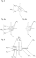
- FIGS 1a - 1c steps of an exemplary first embodiment of an installation method according to the present invention are illustrated by stylised cross sections.
- the method serves to install a fastener bracket 10 according to an exemplary embodiment of the present invention on a holding structure 1 of an aircraft structure such as a fuselage, a wing, and/or an empennage of or for an aircraft.
- the holding structure 1 may in particular be a stiffener such as a frame, a stringer, a rib, or a spar.
- the fastener bracket 10 is formed as a single piece comprising a plate portion 11, two pins 12 and a mount portion 13. According to the present invention, the pins 12 are at least partially made of a remouldable material (not visible).
- the fastener bracket 10 is monolithic. It may preferably entirely consist of a metal and/or of an alloy and/or of a (possibly fibre-reinforced) thermoplastic; in the latter case, the fastener bracket 10 is particularly lightweight.
- the plate portion 11 has a first surface S and a second surface S' opposite to the first surface.
- the pins 12 protrude in parallel from the first surface S which in Figure 1a is shown to face the 1.
- the mount portion 13 protrudes from the second surface S' of the plate portion 11.
- the mount portion 13 is configured to be connected with an element to be fastened to the holding structure 1 (not shown).
- the mount portion may comprise a thread said element may be screwed on, and/or a retainer clip and/or a loop respectively adapted to hold said element (not shown).
- the fastener bracket 10 is moved, in a direction indicated by an arrow, relative to the holding structure 1.
- the pins 12 are inserted into respective holes H arranged within the holding structure 1.
- Figure 1b the insertion is shown to be completed.
- the plate portion 11 abuts on the holding structure 1, which is pierced by the pins 12.
- the pins12 are adjusted on their final length and the end part of the pins 12 that is not needed for deformation, shown in Figure 1c , is cut off. The end part of the pins 12 that is not needed for deformation is cut off prior to deforming.
- the pins 12 are at least partially made of a remouldable material
- the pins can be deformed, e.g. by applying thermal heat and pressure (in particular, heat stamping, heat-conduction-fastening, and/or heating gas fastening), by performing infrared heating and pressure, and/or by performing ultrasonic melting.
- thermal heat and pressure in particular, heat stamping, heat-conduction-fastening, and/or heating gas fastening
- FIGS 2a - 2d steps of an exemplary second embodiment of an installation method according to the present invention are illustrated by stylised cross sections.
- a fastener kit 100 2 according to an exemplary embodiment of the present invention is installed on a holding structure 1 of an aircraft structure.
- the fastener kit comprises a fastener bracket 10 2 according to an embodiment of the present invention, and a counter component 20 2 .
- the fastener bracket 10 2 is configured alike the fastener bracket 10 shown in Figures 1a - 1c and described above. In particular, it is formed as a single piece comprising a plate portion 11 2 and two pins 12 2 which are at least partially made of a remouldable material and which are to be inserted in holes H in the holding structure 1, as indicated by an arrow in Figure 2a .
- the fastener bracket 10 2 is illustrated after the insertion.
- the counter component 20 2 in this exemplary case comprises a counter plate 21 2 with two holes L.
- the fastener kit 100 2 shown in Figures 2a - 2d is configured as a bracket pair.
- the counter component 20 2 is designated to be slipped onto the pins of the fastener bracket.
- Figure 2c shows the fastener kit 100 2 after the counter component 20 2 has been slipped onto the pins 12 2 .
- the plate portion 11 2 of the fastener bracket 10 2 and the counter plate 21 2 of the counter component 20 2 extend parallel to each other on opposite sides of the holding structure 1, with the pins 12 2 penetrating the holding structure and the counter component 20 2 through the respective holes H, L thereof.
- the pins 12 2 are adjusted on their final length and the end part of the pins 12 2 that is not needed for deformation, shown in Figure 2d , is cut off. The end part of the pins 12 2 that is not needed for deformation is cut off prior to deforming.
- Figure 2d shows the fastener kit being fixed to the holding structure 1 by deforming the pins 12 2 so as to each forming a respective knob inhibiting that the counter component 20 2 can slip off the pins 12 2 and that the pins 12 2 on their part can slip back out of the holes H of the holding structure 1.
- a mount portion 13 2 of the fastener bracket 10 2 can be connected with an element, and on the opposite side of the holding structure 1, a fixation portion 22 2 of the counter element 20 2 can be connected with an item (not shown).
- the item may coincide with said element or be different therefrom.
- said element and said item each may be an object - such as an electric cable or a thermal insulation material - to be fastened to the holding structure 1, or one or both of said element and item may be a respective fixation structure (such as a screw and/or a clip, for instance) adapted to be connected with an object to be fastened to the holding structure 1.
- the mount portion 13 2 is of a different type than the fixation portion 22 2 . Accordingly, the mount portion 13 2 and the fixation portion 22 2 may serve to fasten different respective objects to the holding structure 1 (not shown).
- FIG 3 another fastener kit 100 3 according to an exemplary embodiment of the present invention is shown, the fastener kit 100 3 comprising a fastener bracket 10 3 (which in this case is configured alike the fastener bracket 10 shown in Figures 1a -1c and the fastener bracket 10 2 of the fastener kit 100 2 shown in Figures 2a - 2d and described above) and two counter components 30 3 which in this case each are configured as a ring.
- the ring may be at least partially made of a metallic material, such as titanium, aluminium, an alloy and/or stainless steel, for example, and/or of at least one non-metallic material such as ceramic.
- Figure 3 shows the fastener kit 100 3 in a state in which it is installed on the holding structure 1, wherein the pins 12 3 of the fastener bracket 10 3 have been deformed, by applying heat, after the counter components 30 3 each have been slipped onto a respective one of the pins 12s. Therein, the counter components 30 3 served to prevent detrimental thermal impact during the deformation of the pins 12 3 .
- FIGS 4a, 4b steps of a further exemplary embodiment of an installation method according to the present invention are illustrated by stylised cross sections.
- a fastener kit 100 4 is installed to a holding structure 1 of a (not shown) aircraft structure.
- the fastener kit 100 4 comprises a fastener bracket 10 4 which is configured alike the fastener brackets shown in in the preceding figures and described above. Moreover, the fastener kit 100 4 comprises a first counter component 20 4 configured alike the counter component 20 2 shown in Figures 2a - 2d and described above. Furthermore, the fastener kit 200 4 comprises two further counter component 30 4 which each are configured as a ring.
- Figure 4a depicts the fastener kit 100 4 in a situation in which the pins 12 4 have been inserted into holes arranged in the holding structure 1 and thus run through the holding structure, in which further the first counter component 20 4 and the second counter components 30 4 have been slipped onto the pins projecting from the holes.
- the pins 12 4 are deformed.
- the second counter components 30 4 serve to prevent a negative impact of the heat applied, in particular a disadvantageous effect the heat might otherwise have on the first counter component 20 4 (which advantageously may be at least partially made of a thermoplastic).
- the result of the deformation is shown in Figure 4b .
- Figure 5 shows a fastener kit 100 5 according to a further exemplary embodiment of the present invention, which comprises a fastener bracket 10 according to an embodiment of the present invention, and a counter element 20 5 comprising a counter plate 21 5 .
- the fastener kit 100 5 shown in Figure 5 is configured as a bracket pair.
- the pins 12 5 of fastener bracket 10 5 are partially made of a remouldable material (not visible) and further each include a portion of a respective fireproof member 14 5 extending in the pin 12 5 .
- the fireproof members 14 5 each are shaped as a rod having different diameters along its longitudinal axis.
- the fireproof members 14 5 are stabilised in the plate portion 11 5 of the fastener bracket 10 5 by respective fireproof elements 15 5 embedded in the plate portion 11 5 .
- the fireproof elements 15 5 are configured as rings the rod-like fireproof members 14 5 run through.
- the counter component 20 5 of the fastener kit 100 5 comprises a fixation portion 22 5 protruding from the counter plate 21 and configured to be connected with an item to be fastened to the holding structure 1.
- the counter component 20 5 further comprises a fireproof part 23 5 which is partially included in the fixation portion 22 5 , in which it extends. It is shaped as a rod with different diameters along its longitudinal axis.
- the fireproof members 14 5 , the fireproof elements 15 5 and the fireproof part 23 5 improve a fire resistance of the fastener kit 100 5 , as they prevent failure thereof in case of abnormal heat (such as a fire) causing a softening/ melting of the remouldable material included therein.
- They may in particular be made of the same or different material/s.
- one, two or all of them may at least partially be made of a metallic material, such as titanium, aluminium, and alloy, and/or stainless steel, for example, or of a metallic material, such as titanium, aluminium, an alloy and/or stainless steel, for example, and/or of at least one non-metallic material such as ceramic.
- FIGs 6a, 6b steps of a fastening method according to an embodiment of the present invention are shown.
- a further fastener kit comprising a fastener bracket 10 6 and a counter component 20 6 is installed on a holding structure 1.
- the fastener bracket 10 6 is configured alike the fastener bracket 10 5 shown in Figure 5 and described with respect thereto.
- the counter component 20 6 comprises a counter plate 21 6 , a fixation portion 22 6 and, extending therein, a rod-like fireproof part 23 6 .
- said rod-like fireproof part 23 6 is a first fireproof part which is stabilised by a further fireproof part 24 6 , which in this case is configured as a ring the first fireproof part 23 6 runs through.
- FIG 6b a further exemplary step of the fastening method is shown, in which step an installation ring 40 6 is slipped onto the fixation portion 23 6 , which installation ring 40 6 may serve to fastening an insulation material (not shown).
- FIG. 7 shows a further exemplary fastener kit 100 7 according to the present invention as being installed on a holding structure 1 of an aircraft structure.
- the fastener kit 100 7 comprises a fastener bracket 10 7 and a first counter component 20 7 which in the situation depicted has been slipped onto the pins of the fastener bracket 10 7 .
- the fastener kit 100 7 further comprises two second counter components 30 7 , each being configured as a ring, which in the situation depicted also have been slipped onto the pins of the bracket, and two interlocking components 50 7 which in this case are configured as screw nuts.
- the fastening bracket 10 7 includes two fireproof members 14 7 each extending in a respective one of the pins, wherein the free ends of thefireproof members 14 7 comprise a thread (not visible), and the interlocking components 50 7 are mechanically mounted on the pins, more specifically, on the fireproof members thereof, by screwing them on said threads.
- FIG. 8 depicts a portion of an aircraft structure 1000 according to an exemplary embodiment of the present invention, the aircraft structure in this case being embodied as a fuselage.
- the aircraft structure 1000 in particular comprises two supporting structures 1 (which in this case are frames) stabilising a shell 2 of the aircraft structure 1000.
- Various fastener kits 100 8 are installed on each of the frames, the fastener kits 100 8 each comprising a fastener bracket 10 8 with two pins 12 8 and a mount portion 13 8 , and a counter component 20 8 with a fixation portion 22 8 .
- the pins 12 8 each extend through the holding structure 1 and through respective holes in the counter component 20 8 which thereby is fixed.
- the mount portion 13 8 and the fixation portion 22 8 each are configured to be connected with a (respective or same) element/ item (not shown in Figure 8 ), which may be an object to be fastened to the holding structure (such as an electric cable or a thermal insulation material) or which may be an intermediate, in particular a fixation structure (such as a clip or screw) adapted to be connected with such object.
- a fixation structure such as a clip or screw
- a fastener bracket 10, 10 2 10 3 , 10 4 , 10 5 , 10 6 , 10 7 , 10 8 configured to be installed on a holding structure 1.
- the fastener bracket is formed as a single piece comprising a plate portion 11, 11 2 , 11 5 and at least two pins 12, 12 2 , 12 3 , 12 4 , 12 5 , 12 7 protruding in parallel from a first surface S of the plate portion 11, 11 2 , 11 5 .
- the at least two pins 12, 12 2 , 12 3 , 12 4 , 12 5 , 12 7 are at least partially made of a remouldable material.
- a fastener kit 100 2 , 100 3 , 100 4 , 100 5 , 100 7 comprising such fastener bracket 10, 10 2 10 3 , 10 4 , 10 5 , 10 6 , 10 7 and at least one counter component 20 2 , 20 4 , 20 5 , 20 6 , 20 8 , 30 3 , 50 7 .
- an aircraft structure 1000 comprising at least one fastener bracket or even fastener kit is disclosed, as are an installation method of installing a fastener bracket, and a fastening method of fastening an object to a holding structure 1 of an aircraft structure 1000.
Landscapes
- Engineering & Computer Science (AREA)
- Mechanical Engineering (AREA)
- General Engineering & Computer Science (AREA)
- Aviation & Aerospace Engineering (AREA)
- Connection Of Plates (AREA)
Priority Applications (3)
| Application Number | Priority Date | Filing Date | Title |
|---|---|---|---|
| EP23170478.4A EP4454867A1 (de) | 2023-04-27 | 2023-04-27 | Befestigungsklammer, befestigungskit, aircra. struktur und verfahren |
| CN202410496570.8A CN118855827A (zh) | 2023-04-27 | 2024-04-24 | 紧固件托架、紧固件套件、飞行器结构和方法 |
| US18/646,050 US20240359789A1 (en) | 2023-04-27 | 2024-04-25 | Fastener bracket, fastener kit, aircraft structure and methods |
Applications Claiming Priority (1)
| Application Number | Priority Date | Filing Date | Title |
|---|---|---|---|
| EP23170478.4A EP4454867A1 (de) | 2023-04-27 | 2023-04-27 | Befestigungsklammer, befestigungskit, aircra. struktur und verfahren |
Publications (1)
| Publication Number | Publication Date |
|---|---|
| EP4454867A1 true EP4454867A1 (de) | 2024-10-30 |
Family
ID=86272428
Family Applications (1)
| Application Number | Title | Priority Date | Filing Date |
|---|---|---|---|
| EP23170478.4A Pending EP4454867A1 (de) | 2023-04-27 | 2023-04-27 | Befestigungsklammer, befestigungskit, aircra. struktur und verfahren |
Country Status (3)
| Country | Link |
|---|---|
| US (1) | US20240359789A1 (de) |
| EP (1) | EP4454867A1 (de) |
| CN (1) | CN118855827A (de) |
Citations (4)
| Publication number | Priority date | Publication date | Assignee | Title |
|---|---|---|---|---|
| US4718801A (en) * | 1986-07-24 | 1988-01-12 | Microdot Inc. | Composite core fastener |
| GB2205374A (en) * | 1987-05-19 | 1988-12-07 | Rockwell International Corp | Composite fasteners for fastening structural components |
| US20090047100A1 (en) * | 2007-08-14 | 2009-02-19 | Keener Steven G | Method and apparatus for fastening components using a composite two-piece fastening system |
| US10160029B2 (en) * | 2014-10-22 | 2018-12-25 | Ford Global Technologies, Llc | System and method for assembling vehicle components with reinforced moldable rivet |
-
2023
- 2023-04-27 EP EP23170478.4A patent/EP4454867A1/de active Pending
-
2024
- 2024-04-24 CN CN202410496570.8A patent/CN118855827A/zh active Pending
- 2024-04-25 US US18/646,050 patent/US20240359789A1/en active Pending
Patent Citations (4)
| Publication number | Priority date | Publication date | Assignee | Title |
|---|---|---|---|---|
| US4718801A (en) * | 1986-07-24 | 1988-01-12 | Microdot Inc. | Composite core fastener |
| GB2205374A (en) * | 1987-05-19 | 1988-12-07 | Rockwell International Corp | Composite fasteners for fastening structural components |
| US20090047100A1 (en) * | 2007-08-14 | 2009-02-19 | Keener Steven G | Method and apparatus for fastening components using a composite two-piece fastening system |
| US10160029B2 (en) * | 2014-10-22 | 2018-12-25 | Ford Global Technologies, Llc | System and method for assembling vehicle components with reinforced moldable rivet |
Also Published As
| Publication number | Publication date |
|---|---|
| CN118855827A (zh) | 2024-10-29 |
| US20240359789A1 (en) | 2024-10-31 |
Similar Documents
| Publication | Publication Date | Title |
|---|---|---|
| CN101474658B (zh) | 组装复合材料结构的方法和装置 | |
| US6405425B1 (en) | Fastening assembly and method for fastening a multi-layered laminate together | |
| CN101273207B (zh) | 将轻质板体固定在支座上的固定装置 | |
| US5816761A (en) | Lightweight structural blind fastener | |
| JP5156356B2 (ja) | 航空機構造およびそれを製造するための方法 | |
| US20140056664A1 (en) | High performance sleeved interference fasteners for composite applications | |
| KR20120060916A (ko) | 전도도가 향상된 슬리브형 파스너 및 그 제조 방법 | |
| EP4454867A1 (de) | Befestigungsklammer, befestigungskit, aircra. struktur und verfahren | |
| US20240133409A1 (en) | Blind fastener and method of installation thereof | |
| US20190063485A1 (en) | Method and systems for inserting a coated fastener in an assembly | |
| WO2023021333A1 (en) | Fastening collars, multi-piece fasteners, and methods for fastening | |
| US4679292A (en) | Method for securing a panel to a structural member | |
| US4813807A (en) | Memory metal connector for panels | |
| US9829018B2 (en) | Non-cylindrical fastening systems and related methods | |
| EP1235987B1 (de) | Befestigungsvorrichtung und verfahren zum befestigen eines verbundlaminats | |
| CN117716137A (zh) | 紧固套环、多件式紧固件以及用于紧固的方法 | |
| CN223306097U (zh) | 螺母组件 | |
| CN116547459A (zh) | 紧固套环、多件式紧固件以及用于紧固的方法 | |
| CN116374190A (zh) | 一种验证装配应力对寿命影响的试验件 | |
| EP3339660B1 (de) | Befestigungsvorrichtung und verfahren zum verbinden einer endmaske eines schienenfahrzeugs an einem strukturelement eines wagenkastens und entsprechendes schienenfahrzeug | |
| Tanis et al. | Composite Fasteners—A Compatible Joining Technique for Fibrous Composites in Structural Design | |
| GB2145185A (en) | Two piece fastener for adjacent workpieces | |
| US8561266B2 (en) | Holder arrangement for an aircraft or a spacecraft and an aircraft or a spacecraft | |
| Bickford | 2. 2. DevelopmentofFitting (lug) Stresses |
Legal Events
| Date | Code | Title | Description |
|---|---|---|---|
| PUAI | Public reference made under article 153(3) epc to a published international application that has entered the european phase |
Free format text: ORIGINAL CODE: 0009012 |
|
| STAA | Information on the status of an ep patent application or granted ep patent |
Free format text: STATUS: THE APPLICATION HAS BEEN PUBLISHED |
|
| AK | Designated contracting states |
Kind code of ref document: A1 Designated state(s): AL AT BE BG CH CY CZ DE DK EE ES FI FR GB GR HR HU IE IS IT LI LT LU LV MC ME MK MT NL NO PL PT RO RS SE SI SK SM TR |
|
| STAA | Information on the status of an ep patent application or granted ep patent |
Free format text: STATUS: REQUEST FOR EXAMINATION WAS MADE |
|
| 17P | Request for examination filed |
Effective date: 20250213 |