EP4454980A1 - Mécanisme de roulement à chenilles pour un engin agricole et engin agricole - Google Patents
Mécanisme de roulement à chenilles pour un engin agricole et engin agricole Download PDFInfo
- Publication number
- EP4454980A1 EP4454980A1 EP24157363.3A EP24157363A EP4454980A1 EP 4454980 A1 EP4454980 A1 EP 4454980A1 EP 24157363 A EP24157363 A EP 24157363A EP 4454980 A1 EP4454980 A1 EP 4454980A1
- Authority
- EP
- European Patent Office
- Prior art keywords
- crawler track
- main frame
- main
- wheels
- frame
- Prior art date
- Legal status (The legal status is an assumption and is not a legal conclusion. Google has not performed a legal analysis and makes no representation as to the accuracy of the status listed.)
- Granted
Links
Images



Classifications
-
- B—PERFORMING OPERATIONS; TRANSPORTING
- B62—LAND VEHICLES FOR TRAVELLING OTHERWISE THAN ON RAILS
- B62D—MOTOR VEHICLES; TRAILERS
- B62D55/00—Endless track vehicles
- B62D55/08—Endless track units; Parts thereof
- B62D55/104—Suspension devices for wheels, rollers, bogies or frames
- B62D55/112—Suspension devices for wheels, rollers, bogies or frames with fluid springs, e.g. hydraulic pneumatic
-
- B—PERFORMING OPERATIONS; TRANSPORTING
- B62—LAND VEHICLES FOR TRAVELLING OTHERWISE THAN ON RAILS
- B62D—MOTOR VEHICLES; TRAILERS
- B62D55/00—Endless track vehicles
- B62D55/08—Endless track units; Parts thereof
- B62D55/10—Bogies; Frames
-
- B—PERFORMING OPERATIONS; TRANSPORTING
- B62—LAND VEHICLES FOR TRAVELLING OTHERWISE THAN ON RAILS
- B62D—MOTOR VEHICLES; TRAILERS
- B62D55/00—Endless track vehicles
- B62D55/08—Endless track units; Parts thereof
- B62D55/12—Arrangement, location, or adaptation of driving sprockets
-
- B—PERFORMING OPERATIONS; TRANSPORTING
- B62—LAND VEHICLES FOR TRAVELLING OTHERWISE THAN ON RAILS
- B62D—MOTOR VEHICLES; TRAILERS
- B62D55/00—Endless track vehicles
- B62D55/08—Endless track units; Parts thereof
- B62D55/30—Track-tensioning means
-
- A—HUMAN NECESSITIES
- A01—AGRICULTURE; FORESTRY; ANIMAL HUSBANDRY; HUNTING; TRAPPING; FISHING
- A01D—HARVESTING; MOWING
- A01D69/00—Driving mechanisms or parts thereof for harvesters or mowers
-
- B—PERFORMING OPERATIONS; TRANSPORTING
- B62—LAND VEHICLES FOR TRAVELLING OTHERWISE THAN ON RAILS
- B62D—MOTOR VEHICLES; TRAILERS
- B62D55/00—Endless track vehicles
- B62D55/08—Endless track units; Parts thereof
- B62D55/30—Track-tensioning means
- B62D55/305—Track-tensioning means acting on pivotably mounted idlers
Definitions
- the present application relates to a crawler track for an agricultural working machine according to the preamble of claim 1. Furthermore, the present application relates to an agricultural working machine according to the preamble of claim 11.
- the crawler track comprises a front main wheel and a rear main wheel. These main wheels are also referred to in technology as so-called "idler wheels". Typically, one of the main wheels, usually the rear one, can be driven in rotation, while the other main wheel serves passively to guide a running belt that spans the main wheels. The latter is also part of the crawler track.
- the main wheels are arranged opposite one another or one behind the other in the longitudinal direction of the crawler track.
- the front main wheel is assigned to a front main frame and the rear main wheel to a rear main frame. This assignment can consist in particular in the main wheels being arranged directly or indirectly on their respective main frame and each being mounted so that it can rotate about an axis of rotation.
- the front main wheel can be mounted on a swivel arm, forming its axis of rotation, which is arranged on the front main frame.
- the swivel arm is connected to the main frame and forms a swivel joint, so that the swivel arm can be swiveled relative to the main frame. Since the axis of rotation of the main wheel is arranged at a distance from the swivel joint of the swivel arm on the latter, a swiveling of the swivel arm relative to the front main frame is accompanied by a movement of the swivel axis of the front main wheel on a circular path around the swivel joint.
- the swivel arm can preferably also interact with a piston-cylinder unit, by means of which a swivel movement of the swivel arm can be generated and thus the belt tension of the running belt can be adjusted.
- a piston-cylinder unit is referred to in technology as a "belt tensioning cylinder”.
- At least two support wheels are arranged in an intermediate area between the two main wheels. These are also known in technology as so-called “mid rollers”.
- the support wheels typically have a smaller diameter than the main wheels. Like the main wheels, they are in direct contact with the running belt, with the support wheels being in contact with a lower section of the running belt, which typically comes into direct contact with the ground when the crawler track is in operation. In this way, forces acting on the crawler track can be diverted into the ground via both the two main wheels and the two support wheels via the running belt.
- the crawler track also includes a pivot point, by means of which it can be pivotally connected to the body of a respective work machine, forming a machine axle.
- a crawler track is arranged at opposite ends of a front axle of the respective work machine.
- the respective crawler track is pivoted to the front axle of the work machine at the pivot point mentioned, so that the work machine stands on a respective surface by means of the crawler tracks and the work machine can be propelled forward via the crawler tracks.
- the two main frames, to which the main wheels are assigned, are pivotably coupled to one another. This means that the main frames can pivot against one another about a common pivot axis.
- This pivot axis is preferably identical to the machine axis at the articulation point of the crawler track.
- the pivot axis and the machine axis are each oriented horizontally and perpendicularly to a belt plane spanned by the running belt.
- the support wheels are arranged on a common support frame, one behind the other in relation to a longitudinal axis of the crawler track.
- the main wheels and the support wheels are therefore arranged "in series" when viewed in the longitudinal direction of the crawler track, with the front main wheel forming a front end of the crawler track, then the two support wheels follow and finally the rear main wheel forming the rear end of the crawler track.
- a support wheel swing arm is provided, by means of which the support frame is pivotally connected to the front main frame.
- the support wheel swing arm is connected in an articulated manner to both the front main frame and the support frame.
- the support wheel swing arm is therefore designed as a pendulum rod in mechanical terms.
- the articulated connection of the two main frames and the articulated connection of the support wheel swing arm with the front main frame means that the main wheels and the support wheels can be raised separately when driving over an obstacle without the rest of the crawler track lifting off the ground.
- a crawler track typically comprises at least one piston-cylinder unit that is connected at a first end to the support wheel swing arm and at a second end to the front main frame. It is also known that the crawler track comprises at least one further piston-cylinder unit that connects the front main frame and the rear main frame to one another.
- the task for such piston-cylinder units is basically to even out the force distribution across the individual wheels, even when obstacles are driven over, i.e. the crawler track is not completely resting on an at least essentially flat surface. The task is to ensure that forces transferred via the crawler track are transferred as evenly as possible across the wheels into the surface.
- the present application is therefore based on the object of providing a crawler track for an agricultural work machine which is constructed more simply than the prior art.
- the crawler track according to the invention is characterized by a coupling member which is coupled at its first end ("swing end") to the support wheel swing arm and at its second end ("frame end") to the rear main frame.
- the rear main frame and the support wheel swing arm are coupled to one another in a force-transmitting manner by means of the coupling member.
- the crawler track is designed to be free of further connections between the support wheel swing arm and the front or rear main frame, apart from the coupling member mentioned and the articulated linkage to the front main frame.
- the crawler track according to the invention has many advantages.
- a force distribution between the main wheels and the support wheels is created solely by means of the one coupling link between the support wheel swing arm and the rear main frame.
- This is illustrated by way of example using the following case distinctions: first, consider the case where the front main wheel drives over an obstacle and is thereby raised relative to the support wheels and the rear main wheel. The raising of the front main wheel is accompanied by the raising of the front main frame on which the support wheel swing arm is mounted.
- the coupling link is hinged to the support wheel swing arm with its swing end. Accordingly, the coupling link is also raised a certain amount.
- the amounts of the raising of the front main wheel and the coupling link are in the ratio of their respective distances in relation to the pivot axis around which the front main frame is pivoted as the front main wheel is raised. Since the coupling link is coupled to the rear main frame at the end of the frame opposite the swing arm end, the rear main frame is also raised a little as the coupling link is raised. Since both the support wheel swing arm is articulated to the support frame and the rear main frame is articulated to the rear main wheel, the rear main wheel and the support wheels remain at their previous height and are therefore not lifted off the ground.
- the coupling link ensures that the support wheels continue to be used to transfer forces and thus contribute to the transfer of forces from the respective work machine to the ground.
- the support wheels drive over an obstacle and are raised accordingly.
- This is also accompanied by a raising of the support wheel swing arm to which the coupling link is hinged.
- the support wheel swing arm is only connected to the front main frame by forming a joint
- the front main frame is only moved indirectly, namely as a result of a raising of the rear main frame via the coupling link and an associated raising of the connection point at which the front main frame is connected to the rear main frame by forming the joint axis.
- the front main wheel is assigned to the front main frame by forming its axis of rotation, the pivoting of the front main frame is not accompanied by a raising of the front main wheel. The latter is therefore still in contact with the ground via the running belt and can thus divert forces acting on the crawler track into the ground.
- the crawler track according to the invention therefore has the particular advantage that, in the simplest design with just a single coupling link, it ensures that forces are continuously and reliably transferred into the ground via the two main wheels and the two support wheels.
- This allows the crawler track to be constructed in a particularly simple manner, whereby in particular a second coupling link, which in the prior art is typically designed as a piston-cylinder unit, can be dispensed with.
- the coupling link is aligned in such a way that a straight link axis of the coupling link, which connects the swing arm end and the frame end of the coupling link, is inclined by a maximum of 15°, preferably a maximum of 10°, more preferably a maximum of 5°, to a vertical.
- This embodiment has the advantage that the force distribution between the main wheels and the support wheels can be achieved particularly easily. In particular, no other compensating elements or the like are required to ensure the desired amount of force is introduced into the support wheel swing arm and the support wheels if the coupling link were oriented "inclined".
- the crawler track has a central main joint that forms the articulation point and to which it is connected to a respective axle of a work machine to form the machine axis.
- the pivot axis, on which the front main frame and the rear main frame are pivotally connected to one another, is also formed on this central main joint.
- the articulation point - and thus the machine axis and the pivot axis - is preferably located centrally on the crawler track when viewed in the longitudinal direction of the crawler track, so that a horizontally measured distance of the axis of rotation of the front main wheel from the pivot axis is at least essentially as large as a horizontally measured distance of the axis of rotation of the rear main wheel from the pivot axis.
- This design also contributes to simplifying the crawler track, since the kinematics of the possible relative movements of the individual elements to one another are simplified compared to a design in which the pivot axis and machine axis are arranged separately from one another.
- the swing end and the frame end of the coupling member are arranged on the same side of a vertically oriented center plane, which includes the pivot axis, when viewed in the longitudinal direction of the crawler track.
- This center plane which is oriented perpendicular to a belt plane spanned by the running belt, divides the crawler track into a front section and a rear section, the front section comprising the front main frame and the front main wheel and the rear section comprising the rear main frame and the rear main wheel.
- the pivot axis is preferably located in line with its position in the machine axis and further preferably in a center of the crawler track viewed in the longitudinal direction.
- the arrangement of the coupling link on one side of the central plane, preferably on the side of the front section, also contributes to particularly simple kinematics of the crawler track.
- the distance of the coupling link from the swivel axis can be used to adjust the force ratio in which the support wheel swing arm and thus the support wheels are subjected to forces or used to dissipate forces into the ground.
- the rule here is that the support wheels cause a greater force transfer the closer the swing end of the coupling link is to the support frame when viewed along the support wheel swing arm.
- the swing end can be arranged exactly in the middle of the support wheel swing arm, so that forces that are introduced into the support wheel swing arm by means of the coupling link are split equally between the linkage of the support wheel swing arm to the front main frame and the support frame.
- a shift of the swing end along the support wheel swing arm leads to corresponding to a distribution of forces between the front main frame and the support frame that deviates from the 50/50 division.
- the swing end of the coupling link viewed in a direction parallel to the longitudinal axis of the crawler track, is at a distance from the pivot axis of at most 1/4, preferably at most 1/6, more preferably at most 1/8, of a correspondingly measured wheel distance between the axes of rotation of the main wheels.
- the axes of rotation of the two main wheels and the pivot axis are at least essentially at a common height level, at least when the crawler track is in a central position.
- the pivot axis is in its zero position when the crawler track is in its central position.
- the central position of the crawler track describes a state of the crawler track in which it is standing on a level surface, i.e. neither the main wheels nor the support wheels drive over an obstacle.
- Such a central position of a crawler track is illustrated in the figures of the embodiment.
- the arrangement of the pivot axis at the same height level as the axes of rotation of the main wheels means that no torque is caused about the pivot axis as a result of belt tension in the running belt. Due to the at least substantially identical vertically measured distance of an upper section of the running belt from the pivot axis compared to the vertically measured distance of a lower section of the running belt from the pivot axis, the forces prevailing in the running belt cancel each other out due to their identical lever arm in relation to the pivot axis, so that no torque occurs. This only occurs when the pivot axis is displaced vertically from its zero position, which can happen as a result of raising one of the wheels of the crawler track.
- the pivot axis is deflected from its zero position in a vertical direction, as happens, for example, as a result of at least one of the wheels of the drive being raised when driving over an obstacle, a torque caused by the running belt and its belt tension is typically to be expected around the pivot axis, since the distances of the upper section of the running belt and the lower section of the running belt from the pivot axis will generally be different due to the vertical displacement of the pivot axis. Accordingly, the lever arms between the lower section of the running belt and the pivot axis and the upper section of the running belt and the pivot axis are different, so that the torque caused by the belt tension around the The torques generated by the swivel axis do not cancel each other out.
- the crawler track comprises at least one spring element.
- This is preferably designed to be passive, with a spring force caused by the spring element being caused solely by a deflection of the spring.
- a first end of the spring element is connected to the front main frame and a second end of the spring element is connected to the rear main frame.
- the spring element connects the two main frames to one another, so that when the two main frames pivot relative to one another about the pivot axis, the spring element is stretched or compressed. This results in a change in the spring force exerted by the spring element, which is introduced half into the front main frame and half into the rear main frame at the ends of the spring element.
- the spring element is arranged in such a way that an axis of action of the spring element, along which the spring force acts, is located at a distance from the pivot axis. In this way, a torque is exerted on the two main frames about the pivot axis as a result of the spring force. Since the spring force at the ends of the spring element acts in opposite directions on the front main frame and the rear main frame, the front main frame and the rear main frame are subjected to opposing torques about the common pivot axis.
- the spring element is preferably configured in such a way that when the crawler track is in the middle position (and therefore when the swivel axis is in its zero position) it is either in a passive state in which the spring element develops neither tensile forces nor compressive forces, or in a state pre-tensioned with tensile stress or compressive stress, depending on the arrangement. Since the swivel axis cannot typically move downwards from its zero position, as a rule only the case in which the swivel axis is moved vertically upwards from its zero position is to be considered. Accordingly, with regard to the effect of the belt tension, only a state in which the crawler track "stands up" upwards is to be considered, i.e.
- the swivel axis is deflected further upwards as a result of its movement vertically upwards due to the effect of a torque caused by the running belt.
- the spring element now serves to counteract this movement and to so-called "setting up" of the crawler track. If the spring element is arranged in such a way that the two ends of the spring element move away from each other during a described setting up movement of the crawler track, the spring element is preferably designed as a tension spring that is pre-tensioned with a tensile stress. Conversely, the spring element can also be arranged in such a way that its two ends are located at points on the front main frame and the rear main frame that move towards each other as a result of the setting up of the crawler track.
- the spring element is preferably designed as a compression spring that is pre-tensioned with a compression stress.
- the spring element should act in such a way that it counteracts the pivoting of the front main frame relative to the rear main frame caused by the setting up of the crawler track.
- the crawler track has an active piston-cylinder unit, the first end of which is connected to the front main frame and the second end of which is connected to the rear main frame.
- the piston-cylinder unit is intended and set up to actively apply an opposing torque to the main frames about the common pivot axis.
- the active application of forces is therefore possible here.
- a piston-cylinder unit can be a hydraulic cylinder.
- the design of the crawler track with such a piston-cylinder unit has the advantage that the two main frames can be deliberately pivoted relative to each other about the pivot axis, and thus not only a counteraction to a possible installation of the crawler track can be brought about.
- the two main frames can be deliberately pivoted towards each other around the pivot axis, so that the force transfer via the two main wheels into the ground is reduced and the force transfer via the support wheels is increased accordingly.
- Such operation can be advantageous in the area of a headland, for example, in order to protect the ground from the introduction of high shear forces.
- Such operation is also conceivable when a particular work machine is travelling on the road.
- the crawler track has both a passive spring element and an active piston-cylinder unit.
- the spring element and the piston-cylinder unit can optionally be installed in the form of a common assembly be designed, wherein the spring element is designed as part of the piston-cylinder unit and acts on the piston at one end and on the cylinder of the piston-cylinder unit at the other end. As explained above, this causes the spring element to act on the front main frame on the one hand and the rear main frame on the other.
- a design of the crawler track can be advantageous in which the coupling member is formed by a piston-cylinder unit.
- the coupling member is preferably intended and set up to dampen movements that the support wheels and the rear main frame perform relative to one another.
- the coupling element is formed by a piston-cylinder unit, it can also be particularly advantageous if it is designed to be double-acting.
- a piston-side secondary pressure chamber can be pressurized, whereby a pressure in a cylinder-side main pressure chamber can be set. This can be done in particular in such a way that the pressure in the main pressure chamber is within a preset range.
- a pressure level in the cylinder-side main pressure chamber can be deliberately kept within a certain range. This has the advantage that the coupling element can be kept in an advantageous range of its characteristic curve, i.e. the damping properties of the coupling element can be used in a particularly advantageous manner.
- the working machine comprises a body and two crawler tracks, namely a left and a right crawler track.
- the crawler tracks are each connected to the body via a pivot point.
- the crawler tracks can be connected to a front axle of the working machine.
- the working machine is thus characterized in that at least one of the crawler tracks, preferably both crawler tracks, is or are formed by a crawler track according to the invention in accordance with the present application.
- an agricultural work machine 2 is shown in the form of a self-propelled combine harvester, the body 42 of which interacts with two crawler tracks 1.
- the crawler tracks 1 are connected here to a front axle of the work machine 2.
- the crawler track 1 has a front main wheel 3 , a rear main wheel 4 and two support wheels 9 , 10.
- the crawler track 1 also comprises a running belt 11 which spans the two main wheels 3, 4.
- the main wheels 3 , 4 are arranged opposite one another when viewed along a longitudinal axis 16 of the crawler track 1.
- the support wheels 9, 10 are arranged in an intermediate region between the main wheels 3 , 4. Overall, forces which are diverted from the work machine 2 into the crawler track 1 are transferred into a subsoil via both the main wheels 3 , 4 and the support wheels 9 , 10 .
- the design of a crawler track 1 according to the invention is fundamentally similar to known crawler tracks according to the state of the art.
- One such track is shown by way of example in Figure 2
- the crawler track 1 there has a front main frame 5 and a rear main frame 6.
- the two main frames 5 , 6 are pivotable relative to each other at a central articulation point 12 of the crawler track 1 , forming a pivot axis 14. connected to each other.
- the pivot axis 14 coincides with a machine axis 13 formed at the articulation point 12 , around which the crawler track 1 as a whole is pivotably mounted about a respective axis of the working machine 2.
- the machine axis 13 and the pivot axis 14 are oriented horizontally and perpendicularly to a belt plane which is spanned by the running belt 11.
- the belt plane is formed by the drawing plane.
- the pivot axis 14 is arranged centrally with respect to the longitudinal axis 16 of the crawler track 1 , so that a vertical center plane 29 , which is also oriented perpendicular to the belt plane of the running belt 11 and contains the pivot axis 14 , divides the crawler track 1 into two at least substantially equal sections, namely a front section and a rear section.
- the front section contains the front main frame 5 and the front main wheel 3
- the rear section comprises the rear frame 6 and the rear main wheel 4.
- the pivot axis 14 is arranged centrally when viewed in the vertical direction, so that a vertically measured distance of the pivot axis 14 from a lower section 39 of the running belt 11 is just as large as a vertically measured distance of the pivot axis 14 from an upper section 38 of the running belt 11.
- forces prevailing in the running belt 11 as a result of a belt tension of the running belt 11 do not cause any torque about the pivot axis 14 , provided that the latter is in its Figure 2 shown zero position, which the pivot axis 14 assumes when the crawler track 1 is in its central position.
- a support wheel swing arm 17 is articulated to the front main frame 5 , forming a joint 34. At an end of the support wheel swing arm 17 opposite the joint 34 , the latter is connected to a support frame 15 - also forming a joint 35.
- the two support wheels 9 , 10 are each rotatably mounted on this support frame 15 .
- the front main wheel 3 is only indirectly mounted on the front main frame 5. This is done in such a way that the front main wheel 3 is mounted on a swivel arm 33 , which in turn is articulated on the front main frame 5. In this way, a distance of the axis of rotation 7 of the front main wheel 3 from the swivel axis 14 can be changed by pivoting the swivel arm 33 relative to the front main frame 5. This is used to adjust the belt tension of the running belt 11.
- the crawler track 1 shown comprises a belt tensioning cylinder 30 formed by a piston-cylinder unit, which is attached with its first end 36 to the swivel arm 33 and with its second end 37 to the front Main frame 5 is mounted.
- the swivel arm 33 can be swiveled relative to the main frame 5 , whereby the axis of rotation 7 is displaced horizontally in the manner described and the belt tension of the running belt 11 is changed accordingly.
- the crawler track 1 shown further comprises two further piston-cylinder units 31 , 32 , the first-mentioned coupling the front main frame 5 to the rear main frame 6 and the second-mentioned coupling the support wheel swing arm 17 to the front main frame 5.
- the piston-cylinder units 31 , 32 are provided and designed to distribute the forces acting on the crawler track 1 to the main wheels 3 , 4 and the support wheels 9 , 10.
- pressure chambers of the two piston-cylinder units 31 , 32 can be fluidically coupled to one another, so that the displacement of a hydraulic fluid from the pressure chamber of one piston-cylinder unit 31 , 32 results in a corresponding inflow of the fluid into the pressure chamber of the other piston-cylinder unit 31 , 32 .
- the components of the front main frame 5 , rear main frame 6 and support wheel swing arm 17 or support frame 15 are kinematically coupled to one another in order to bring about the aforementioned force distribution and in particular to keep the wheels 3 , 4 , 9 , 10 in continuous contact with the ground. This should be maintained in particular even when the wheels 3 , 4 , 9 , 10 are raised at various times when driving over an obstacle.
- FIG. 3 A first variant of a crawler track 1 according to the invention is shown in Figure 3 illustrated. It differs from the known crawler track 1 in particular by a coupling link 18 which couples the support wheel swing arm 17 to the rear main frame 6. Accordingly, a swing end 19 of the coupling link 18 is connected in an articulated manner to the support wheel swing arm 17 , while a frame end 20 of the coupling link 18 is connected in an articulated manner to the rear main frame 6.
- the coupling link 18 acts mechanically as a pendulum rod which can only transmit normal forces, but does not enable the transmission of torques between the support wheel swing arm 17 and the rear main frame 6.
- the coupling link 18 results in the front main frame 5 , the support wheel swing arm 17 and the rear main frame 6 being kinematically coupled to one another.
- the coupling element 18 alone ensures that when one of the wheels 3 , 4 , 9 , 10 is raised, the remaining wheels 3 , 4 , 9 , 10 remain in contact with the ground and accordingly a force transfer via these wheels 3 , 4 , 9 , 10 into the ground continues.
- the crawler track 1 according to the invention is significantly simplified compared to the prior art without any restriction of functionality.
- the crawler track 1 according to Figure 3 free of further coupling elements which, for example, couple the support wheel swing arm 17 to the front main frame 5 or the two main frames 5 , 6 to one another.
- the crawler track 1 is constructed in a particularly simple manner without being disadvantageous in terms of its functionality.
- the coupling member 18 is at least substantially vertically oriented, so that it is at least substantially parallel to a vertical 22. This is particularly evident from Figure 3 . Furthermore, the coupling member 18 is located entirely on one side of the pivot axis 14 , whereby in the example shown it is located in the front section of the crawler track 1 on this side of the center plane 29. Furthermore, the coupling member 18 is arranged such that it is located at a horizontally measured distance 23 from the pivot axis 14 , which corresponds to approximately one eighth of a wheel distance 24, also measured horizontally, between the rotation axes 7 , 8 of the two main wheels 3 , 4.
- the coupling member 18 is formed by a piston-cylinder unit. Otherwise, the embodiments are designed in the same way.
- the design of the coupling member 18 as a piston-cylinder unit has the advantage that the coupling member 18 is equipped with a damping effect, whereby sudden forces on the main wheels 3, 4 and/or the support wheels 9, 10 are only transmitted to the axle of the respective working machine 2 in a dampened manner.
- the coupling member 18 can be designed in particular in the manner of a gas spring, wherein a cylinder-side main pressure chamber of the coupling member 18 is filled with a gas that is compressible as a result of the application of force.
- the main pressure chamber can cooperate with a gas reservoir (not shown) for this purpose.
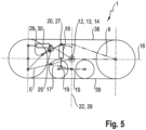
- a further variant of a crawler track 1 according to the invention which in Figure 5 is compared to the one in Figure 4 illustrated second variant is further developed in that the crawler track 1 also has a spring element 25.
- This is connected at a first end 26 to the front main frame 5 and at a second end 27 to the rear main frame 6 , so that spring forces caused by the spring element 25 act in opposite directions directly on the front main frame 5 and the rear main frame 6.
- the spring element 25 is designed to be passive, so that forces caused by the spring element 25 are only due to a deflection of the spring element 25.
- the spring element 25 is designed in the form of a piston-cylinder unit, wherein a piston of the piston-cylinder unit guided in a cylinder is tensioned against the cylinder by means of a spring.
- the piston is connected at the first end of the spring element 25 to the front main frame 5 and the cylinder is connected at the second end 27 of the spring element 25 to the rear main frame 6 .
- the spring element 25 has the function of enabling the above-described setting up of the crawler track 1 as a result of a vertical displacement of the pivot axis 14 from its Figure 5 shown zero position upwards and thereby to control it. Said setting up is due to the fact that a vertically measured distance of the pivot axis 14 is reduced as a result of a displacement of the same from an upper section 38 of the running belt 11 , while a similarly measured distance of the pivot axis 14 from a lower section 39 of the running belt 11 is increased.
- the spring element 25 serves to counteract an increase in the distance between the two ends 26, 27 of the spring element 25 as a result of such a movement of the two main frames 5, 6 . In the example shown, this is done in such a way that the spring of the spring element 25 acting between the piston and the cylinder is compressed and thereby counteracts the piston from extending out of the cylinder. This causes the two ends 26, 27 of the spring element 25 towards each other, whereby a torque is applied to the two main frames 5, 6 which counteracts the erection of the crawler track 1 .
- the crawler track 1 is also equipped with a passive spring element 25.
- the spring element 25 is designed as a compression spring, which is compressed during the erection of the crawler track 1 and thereby counteracts the erection.
- the crawler track 1 in the example shown has an active piston-cylinder unit 28, the first end 40 of which cooperates with the front main frame 5 and the second end 41 of which cooperates with the rear main frame 6.
- the piston-cylinder unit 28 is connected to a hydraulic pressure source, which in Figure 6 is not shown. This creates the possibility in particular of applying pressure to a piston-side pressure chamber of the piston-cylinder unit 28 , whereby the piston is retracted into the cylinder. This leads to a shortening of the piston-cylinder unit 28 and thus to a movement of the two ends 40, 41 of the piston-cylinder unit 28 towards one another. At least when the crawler track 1 is in a central position, such a movement is equivalent to the two main wheels 3, 4 being raised and thus relieved of load, while the two support wheels 9, 10 contribute a greater proportion to the removal of the forces acting on the crawler track 1. In this way, it is possible to specifically reduce the forces diverted into the ground via the two main wheels 3, 4, which can be advantageous, for example, when the work machine 2 is turning in the area of a headland or when the respective work machine 2 is traveling on the road.
- the coupling element 18 designed as a piston-cylinder unit is designed to be double-acting.
- a main pressure chamber on the cylinder side is fluidically connected to a gas reservoir for the purpose of fulfilling a damper function, for example, so that the coupling element 18 can act as a gas spring.
- a secondary pressure chamber on the piston side can be actively pressurized, for example by means of a coupling with a hydraulic pressure source of the respective work machine 2. This can ensure that the pressure in the main pressure chamber is "artificially" kept within a predetermined range. This can be advantageous, for example, if a force acting on the crawler track 1 is of such a small amount that the pressure in the main pressure chamber is outside an advantageous range.
- the coupling element 18 in an advantageous range of its characteristic curve in order to make the best possible use of the damping properties of the coupling element 18.
- the pressure in the main pressure chamber can be regulated in such a way that it always lies within a predefined, advantageous range.
Landscapes
- Engineering & Computer Science (AREA)
- Chemical & Material Sciences (AREA)
- Combustion & Propulsion (AREA)
- Transportation (AREA)
- Mechanical Engineering (AREA)
- Harvester Elements (AREA)
Applications Claiming Priority (1)
| Application Number | Priority Date | Filing Date | Title |
|---|---|---|---|
| DE102023110457.8A DE102023110457A1 (de) | 2023-04-25 | 2023-04-25 | Raupenlaufwerk für eine landwirtschaftliche Arbeitsmaschine sowie landwirtschaftliche Arbeitsmaschine |
Publications (2)
| Publication Number | Publication Date |
|---|---|
| EP4454980A1 true EP4454980A1 (fr) | 2024-10-30 |
| EP4454980B1 EP4454980B1 (fr) | 2026-01-21 |
Family
ID=89940982
Family Applications (1)
| Application Number | Title | Priority Date | Filing Date |
|---|---|---|---|
| EP24157363.3A Active EP4454980B1 (fr) | 2023-04-25 | 2024-02-13 | Mécanisme de roulement à chenilles pour un engin agricole et engin agricole |
Country Status (3)
| Country | Link |
|---|---|
| US (1) | US20240359755A1 (fr) |
| EP (1) | EP4454980B1 (fr) |
| DE (1) | DE102023110457A1 (fr) |
Citations (3)
| Publication number | Priority date | Publication date | Assignee | Title |
|---|---|---|---|---|
| DE102014003964A1 (de) | 2014-03-20 | 2015-09-24 | Claas Industrietechnik Gmbh | Raupenfahrzeug |
| EP3483048A1 (fr) * | 2017-11-08 | 2019-05-15 | CLAAS Industrietechnik GmbH | Mécanisme de déplacement sur chenille pour un engin agricole |
| EP3704928A1 (fr) * | 2019-02-27 | 2020-09-09 | CLAAS Selbstfahrende Erntemaschinen GmbH | Machine de récolte et procédé de récolte au moyen d'une machine de récolte |
-
2023
- 2023-04-25 DE DE102023110457.8A patent/DE102023110457A1/de active Pending
-
2024
- 2024-02-13 EP EP24157363.3A patent/EP4454980B1/fr active Active
- 2024-04-25 US US18/645,602 patent/US20240359755A1/en active Pending
Patent Citations (3)
| Publication number | Priority date | Publication date | Assignee | Title |
|---|---|---|---|---|
| DE102014003964A1 (de) | 2014-03-20 | 2015-09-24 | Claas Industrietechnik Gmbh | Raupenfahrzeug |
| EP3483048A1 (fr) * | 2017-11-08 | 2019-05-15 | CLAAS Industrietechnik GmbH | Mécanisme de déplacement sur chenille pour un engin agricole |
| EP3704928A1 (fr) * | 2019-02-27 | 2020-09-09 | CLAAS Selbstfahrende Erntemaschinen GmbH | Machine de récolte et procédé de récolte au moyen d'une machine de récolte |
Also Published As
| Publication number | Publication date |
|---|---|
| DE102023110457A1 (de) | 2024-10-31 |
| US20240359755A1 (en) | 2024-10-31 |
| EP4454980B1 (fr) | 2026-01-21 |
Similar Documents
| Publication | Publication Date | Title |
|---|---|---|
| DE2053073C3 (de) | Mähmaschine | |
| DE3439048A1 (de) | Kraftheber fuer ein hubgeraet | |
| EP3603374A1 (fr) | Engin de travail agricole | |
| EP3242543B1 (fr) | Engin agricole à châssis de roulement supplémentaire | |
| DE102015108505A1 (de) | Aufsattelpflug | |
| EP3172958B1 (fr) | Véhicule automobile comprenant un dispositif d'attelage pour équipement | |
| EP4454980B1 (fr) | Mécanisme de roulement à chenilles pour un engin agricole et engin agricole | |
| EP0176084B1 (fr) | Machine pour épandre des matériaux granulés latéralement | |
| EP1911339B1 (fr) | Char à double disque doté d'un rouleau de guidage en profondeur et accumulateur d'énergie | |
| DE102011111251B4 (de) | Landmaschine | |
| EP4497664A1 (fr) | Mécanisme de roulement à chenilles pour un engin agricole et engin agricole | |
| EP4497663A1 (fr) | Mécanisme de roulement à chenilles pour un engin agricole et engin agricole | |
| DE1455578B2 (de) | Steuervorrichtung fuer ackerschlepper mit einem dreipunktgestaenge sowie einem hydraulischen kraftheber | |
| DE9413007U1 (de) | Fahrrahmen | |
| EP3598882B1 (fr) | Accessoire agricole | |
| AT502053B1 (de) | Anbauvorrichtung für eine landmaschine | |
| EP3756436B1 (fr) | Relevage avant ainsi que machine de travail doté d'un relevage avant | |
| DE9414597U1 (de) | Gezogene Mähmaschine | |
| EP4124221B1 (fr) | Machine agricole et combinaison de machines agricoles | |
| EP4252503B1 (fr) | Faucheuse agricole pouvant fonctionner en poussée | |
| EP3367775B1 (fr) | Bâti d'engin agricole | |
| EP3971066B1 (fr) | Tracteur pourvu de train de roulement à chenilles | |
| DE4111024C2 (fr) | ||
| DE102018118907A1 (de) | Landwirtschaftliche Arbeitsmaschine | |
| DE102018116213A1 (de) | Schneidwerk für eine landwirtschaftliche Arbeitsmaschine sowie Verfahren zu dessen Bedienung |
Legal Events
| Date | Code | Title | Description |
|---|---|---|---|
| PUAI | Public reference made under article 153(3) epc to a published international application that has entered the european phase |
Free format text: ORIGINAL CODE: 0009012 |
|
| STAA | Information on the status of an ep patent application or granted ep patent |
Free format text: STATUS: THE APPLICATION HAS BEEN PUBLISHED |
|
| AK | Designated contracting states |
Kind code of ref document: A1 Designated state(s): AL AT BE BG CH CY CZ DE DK EE ES FI FR GB GR HR HU IE IS IT LI LT LU LV MC ME MK MT NL NO PL PT RO RS SE SI SK SM TR |
|
| P01 | Opt-out of the competence of the unified patent court (upc) registered |
Free format text: CASE NUMBER: APP_63768/2024 Effective date: 20241202 |
|
| STAA | Information on the status of an ep patent application or granted ep patent |
Free format text: STATUS: REQUEST FOR EXAMINATION WAS MADE |
|
| 17P | Request for examination filed |
Effective date: 20250430 |
|
| GRAP | Despatch of communication of intention to grant a patent |
Free format text: ORIGINAL CODE: EPIDOSNIGR1 |
|
| STAA | Information on the status of an ep patent application or granted ep patent |
Free format text: STATUS: GRANT OF PATENT IS INTENDED |
|
| RIC1 | Information provided on ipc code assigned before grant |
Ipc: B62D 55/10 20060101AFI20250904BHEP Ipc: B62D 55/112 20060101ALI20250904BHEP Ipc: B62D 55/30 20060101ALI20250904BHEP |
|
| INTG | Intention to grant announced |
Effective date: 20250924 |
|
| GRAS | Grant fee paid |
Free format text: ORIGINAL CODE: EPIDOSNIGR3 |
|
| GRAA | (expected) grant |
Free format text: ORIGINAL CODE: 0009210 |
|
| STAA | Information on the status of an ep patent application or granted ep patent |
Free format text: STATUS: THE PATENT HAS BEEN GRANTED |
|
| AK | Designated contracting states |
Kind code of ref document: B1 Designated state(s): AL AT BE BG CH CY CZ DE DK EE ES FI FR GB GR HR HU IE IS IT LI LT LU LV MC ME MK MT NL NO PL PT RO RS SE SI SK SM TR |
|
| REG | Reference to a national code |
Ref country code: CH Ref legal event code: F10 Free format text: ST27 STATUS EVENT CODE: U-0-0-F10-F00 (AS PROVIDED BY THE NATIONAL OFFICE) Effective date: 20260121 |
|
| REG | Reference to a national code |
Ref country code: DE Ref legal event code: R096 Ref document number: 502024000623 Country of ref document: DE |
|
| REG | Reference to a national code |
Ref country code: IE Ref legal event code: FG4D Free format text: LANGUAGE OF EP DOCUMENT: GERMAN |
|
| PGFP | Annual fee paid to national office [announced via postgrant information from national office to epo] |
Ref country code: DE Payment date: 20260227 Year of fee payment: 3 |
|
| PGFP | Annual fee paid to national office [announced via postgrant information from national office to epo] |
Ref country code: AT Payment date: 20260301 Year of fee payment: 3 |
|
| PGFP | Annual fee paid to national office [announced via postgrant information from national office to epo] |
Ref country code: BE Payment date: 20260227 Year of fee payment: 3 |
|
| PGFP | Annual fee paid to national office [announced via postgrant information from national office to epo] |
Ref country code: FR Payment date: 20260323 Year of fee payment: 3 |