EP4455041A1 - Verschluss für einen behälter und behälter mit einem solchen verschluss - Google Patents
Verschluss für einen behälter und behälter mit einem solchen verschluss Download PDFInfo
- Publication number
- EP4455041A1 EP4455041A1 EP23169564.4A EP23169564A EP4455041A1 EP 4455041 A1 EP4455041 A1 EP 4455041A1 EP 23169564 A EP23169564 A EP 23169564A EP 4455041 A1 EP4455041 A1 EP 4455041A1
- Authority
- EP
- European Patent Office
- Prior art keywords
- flow control
- control element
- base element
- container
- extension
- Prior art date
- Legal status (The legal status is an assumption and is not a legal conclusion. Google has not performed a legal analysis and makes no representation as to the accuracy of the status listed.)
- Granted
Links
Images




Classifications
-
- B—PERFORMING OPERATIONS; TRANSPORTING
- B65—CONVEYING; PACKING; STORING; HANDLING THIN OR FILAMENTARY MATERIAL
- B65D—CONTAINERS FOR STORAGE OR TRANSPORT OF ARTICLES OR MATERIALS, e.g. BAGS, BARRELS, BOTTLES, BOXES, CANS, CARTONS, CRATES, DRUMS, JARS, TANKS, HOPPERS, FORWARDING CONTAINERS; ACCESSORIES, CLOSURES, OR FITTINGS THEREFOR; PACKAGING ELEMENTS; PACKAGES
- B65D47/00—Closures with filling and discharging, or with discharging, devices
- B65D47/04—Closures with discharging devices other than pumps
- B65D47/06—Closures with discharging devices other than pumps with pouring spouts or tubes; with discharge nozzles or passages
- B65D47/08—Closures with discharging devices other than pumps with pouring spouts or tubes; with discharge nozzles or passages having articulated or hinged closures
- B65D47/0804—Closures with discharging devices other than pumps with pouring spouts or tubes; with discharge nozzles or passages having articulated or hinged closures integrally formed with the base element provided with the spout or discharge passage
- B65D47/0809—Closures with discharging devices other than pumps with pouring spouts or tubes; with discharge nozzles or passages having articulated or hinged closures integrally formed with the base element provided with the spout or discharge passage and elastically biased towards both the open and the closed positions
- B65D47/0814—Closures with discharging devices other than pumps with pouring spouts or tubes; with discharge nozzles or passages having articulated or hinged closures integrally formed with the base element provided with the spout or discharge passage and elastically biased towards both the open and the closed positions by at least three hinge sections, at least one having a length different from the others
-
- B—PERFORMING OPERATIONS; TRANSPORTING
- B65—CONVEYING; PACKING; STORING; HANDLING THIN OR FILAMENTARY MATERIAL
- B65D—CONTAINERS FOR STORAGE OR TRANSPORT OF ARTICLES OR MATERIALS, e.g. BAGS, BARRELS, BOTTLES, BOXES, CANS, CARTONS, CRATES, DRUMS, JARS, TANKS, HOPPERS, FORWARDING CONTAINERS; ACCESSORIES, CLOSURES, OR FITTINGS THEREFOR; PACKAGING ELEMENTS; PACKAGES
- B65D47/00—Closures with filling and discharging, or with discharging, devices
- B65D47/04—Closures with discharging devices other than pumps
- B65D47/043—Closures with discharging devices other than pumps with pouring baffles, e.g. for controlling the flow
Definitions
- the present invention relates to a closure or a closure device for a container and to a container with such a closure or closure device.
- closures are typically used for products to be dispensed and being contained in a container to which said closure is attached.
- the products to be dispensed are typically fluid products, like e.g. liquids or powdered or granular products, e.g. in the food or beverage area, for example ketchup, but also in other applications, e.g. for cleaning substances, detergents or other products.
- fluid products like e.g. liquids or powdered or granular products, e.g. in the food or beverage area, for example ketchup, but also in other applications, e.g. for cleaning substances, detergents or other products.
- Such closures frequently comprise a membrane valve, typically made from silicone, to ensure a proper and controlled dispensing and to also ensure a proper and controlled stopping or ending of a dispensing process.
- a membrane valve typically made from silicone
- a dispensing bottle comprising a container body and a cap with a base and a flip-top lid is for example known from document EP 3 752 432 B1 .
- Claims 2 to 14 refer to specifically advantageous realizations of a closure according to claim 1.
- the present invention relates to a dispensing closure for a container, said dispensing closure comprising a base element, wherein the base element (200) comprises a deck portion and a skirt portion extending from the deck portion, said skirt portion having attachment means for attaching the base unit to the container, especially a neck of the container, wherein the base element further comprises a dispensing opening for dispensing a fluid.
- the base element further comprises a first flow control element with a plate element (which is a preferred but which is an optional element, which can, in specific embodiments, also be omitted) and at least two, preferably at least three, rack elements extending from the deck portion of the base element to the plate element and being arranged around the dispensing opening such that these rack elements hold or keep the plate element (if provided) in a predetermined distance from said dispensing opening such that fluid is capable of flowing through voids between the plate element (if provided), the rack elements and the deck portion, especially an inner area of the deck portion.
- a second flow control element see hereinafter.
- the plate element could be an essentially flat or plane element, preferably extending in a horizontal direction or it could be a roof or a dome like element or a connection element, in any geometric form, preferably connecting some or more preferably all rack elements.
- the dispensing closure further comprises a second flow control element which is connected to the base element, preferably to the first flow control element, and preferably by snap fitting, such that a void, preferably a ringlike void, is formed between the second flow control element and at least parts or portions of the deck portion of the base element such that fluid is capable of flowing through the void between the second flow control element and the deck portion, and such that flow of liquid between the plate element of the first flow control element and the second flow control element is preferably prevented.
- a second flow control element which is connected to the base element, preferably to the first flow control element, and preferably by snap fitting, such that a void, preferably a ringlike void, is formed between the second flow control element and at least parts or portions of the deck portion of the base element such that fluid is capable of flowing through the void between the second flow control element and the deck portion, and such that flow of liquid between the plate element of the first flow control element and the second flow control element is preferably prevented.
- This specific design leads to an enhanced dispensing process and/or to a proper and smoother dispensing and/or also to an increased mixing of fluid to be dispensed during the dispensing process and before being dispensed out of the dispensing opening to the exterior.
- the present invention relates to a dispensing closure for a container, said dispensing closure comprising a base element, wherein the base element comprises a deck portion and a skirt portion extending from the deck portion, said skirt portion having attachment means for attaching the base unit to the contain-er, especially a neck of the container, wherein the base element further comprises a dispensing opening for dispensing a fluid, while the base of the closure comprises a first flow control element and a second flow control element which are designed and arranged such that a direction of the flow of liquid during dispensing is controlled or influenced by these first and second flow control elements such that the direction of flow is changed at least once, preferably multiple times during the dispensing process.
- An advantage of the present invention or of some of the embodiments and potential realizations disclosed therein is that enhanced dispensing properties can be achieved even without providing a membrane valve, especially a membrane slit valve, typically a silicon valve, a base element and/or closure as described in this application without provision of an additional silicone membrane has the advantage that the complete base element and/or closure can be manufactured from the same a material, which is of advantage for recycling purposes.
- closure and the base element as disclosed in the present application can be also used to together with such a membrane valve, especially a membrane slit valve, preferably inserted and/or positioned in the vicinity or at the dispensing opening or at a dispensing channel of the base element, either within the dispensing channel or in the vicinity thereof, e.g. directly at one and of the dispensing channel.
- a membrane valve especially a membrane slit valve, preferably inserted and/or positioned in the vicinity or at the dispensing opening or at a dispensing channel of the base element, either within the dispensing channel or in the vicinity thereof, e.g. directly at one and of the dispensing channel.
- the dispensing closure also comprises the lid unit, especially in the form of a flip-top lid, being attached to or capable of being attached to the base element.
- this lid is preferably attached to the base element by way of a hinge.
- the lid unit preferably comprises a sealing element for closing or sealing the dispensing opening of the base element when said lid unit is in its closing position.
- the flip-top lid can be moved between a closed and an opened position around the hinge.
- the sealing element is preferably positioned at a top portion, preferably an inner or downwardly directed area of the top portion, being directed towards the base element when the flip-top lid is in its closed position, preferably at a middle or central area.
- the second flow control element is a ringlike element having an inner opening, a ringlike plate portion extending around said inner opening, preferably extending in a planar or in an essentially planar direction, and an outer edge portion, at least partly extending into a direction towards the deck portion of the base element, preferably over a predetermined height.
- the inner opening is preferably a circular cross-section or an essentially circular cross-section, but may be also adapted to other geometric forms, preferably also depending on the form of the first flow control element and especially of the plate of the first flow control element.
- the plate element of the first flow control element has the form of a circular or essentially circular plate, also depending on the geometric form and/or design of the second flow control element.
- the first flow control element is preferably positioned and designed such that the plate element of the first flow control element is extending in a horizontal direction or in a direction parallel to the dispensing opening or in a direction parallel to a deck portion of the base element.
- the plate element has a size or has extensions, preferably in a horizontal direction as described above, which is equal to or comparable to the size or extension of the dispensing opening in the same horizontal direction.
- the dimension of the plate element is slightly smaller than the dimension of the dispensing opening or the cross-section of the dispensing opening, preferably being about 5% to 20%, more preferably about 5% to 10% smaller.
- the dimension of the plate element can be also larger than the dimension of the dispensing opening or the cross-section of the dispensing opening, in a preferred embodiment however not being more than 20% larger, more preferably not more than 10% larger.
- the second flow control element is an element being separate and/or being manufactured separately from the other elements of the closure and especially the base element, while further preferably the first flow control element is unitary with the base element, especially preferably manufactured unitarily, e.g. by injection molding.
- first flow control element and/or the second flow control element are designed and arranged such that these elements can be connected to each other, preferably by snap fitting.
- first flow control element and/or the second flow control element has or have one or more latch elements which can engage with each other, e.g. by formfitting or by enhanced friction and/or a friction created by the one or more latch elements being beyond a predetermined threshold, in order to hold and/or attached the second flow control element to the first flow control element and thereby preferably to the remaining parts of the base element.
- This enables not only an easy and inexpensive manufacturing, especially by injection molding, but also an easy and inexpensive assembly of parts of the closure being manufactured separately, e.g. by injection molding.
- this snap fitting also leads to a reliable connection between first and second flow control element.
- the second flow control element comprises one or more fins, preferably extending along a ringlike plate portion of the second flow control element, preferably on a surface of the ringlike plate portion being directed towards the deck portion of the base element and further preferably extending in a radial or in an essentially radial direction and further preferably extending from the inner opening to an outer edge portion of the second flow control element.
- These fins have the advantage to provide an enhanced ability to the second flow control element and/or also further influence the flow of liquid in order to enhance the dispensing properties.
- the second flow control element comprises an inner opening and at least one extension element, preferably at least two or further preferably at least three ex-tension elements, the at least one extension element being arranged at or around the inner opening such that the at least one extension element is extending towards the deck portion of the base element.
- extension elements have the advantage of further positively influencing the flow of liquid to be dispensed, depending on the position of the extension elements also having the advantage of generating further amendments of the flow direction of the liquidity during dispensing, thereby also enhancing mixture of the liquid to be dispensed.
- the at least one extension element preferably all of the at least one extension elements, has or have a width, preferably measured in a circumferential direction, being different from a width, preferably measured in a circumferential direction, of at least one of the rack elements of the base element, preferably being different from the width of all of the rack elements of the base element, wherein further preferably the angular positions of the extension elements around a circumference of the second flow control element are different from the angular positions of the rack elements (320) of the base element.
- This further enhances the desired flow of liquid to be dispensed, especially the flow direction.
- the second flow control element can be attached, especially by snap fitting, to the first flow control element in any relative angular position, further preferably the second flow control element can be rotated relative to the first flow control element and/or the base element even after the second flow control element has been attached to the first flow control element and/or the base element.
- the base element comprises a ringlike extension being arranged such that it extends at least partly in a direction towards the second flow control element, wherein said ringlike extension preferably has a diameter being smaller than the diameter or the outer extensions of the second flow control element, this ringlike extension further influences the flow and especially the flow direction of the fluid to be dispensed, especially directly before the or in the vicinity of the dispensing opening or a dispensing channel, especially such that the flow direction has to be changed more often, thereby leading to a mixture or homogenization of the fluid before being dispensed.
- the second flow control element has an outer edge portion, which at least partly extends into a direction towards the deck portion of the base element.
- the second flow control element and the part extending towards the deck portion can have a predetermined height, the height being measured in a direction perpendicular to a horizontal direction or perpendicular to a plane direction or horizontal direction of the second flow control element when being assembled and attached to the base element.
- the second flow control element has an outer edge portion at least partly ex-tending into a direction towards the deck portion of the base element, wherein a height of the outer edge portion of the second flow control element and a height of the ringlike extension of the base element are such that the outer edge portion and the ringlike extension at least partly overlap in the height direction, this further enhances the dispensing properties and/or leads to a more frequent change of the flow direction of the liquid to be dispensed or the stronger and/or faster change of the flow direction.
- the base element comprises a further or outer skirt portion extending from the deck portion, the further or outer skirt portion being positioned radially outward of the skirt portion having attachment means for attaching the base unit to the container.
- This further or outer skirt portion enables a better fitting to a variety of containers to which the closure and/or the base element will be attached, and it also leads to a covering or a protection of the skirt or in a skirt portion having attachment means for attaching the base unit to the container.
- the second flow control element comprises a ringlike extension being arranged between an outer edge portion and an inner opening or being arranged between an outer edge portion and one or more extension elements being arranged at or around the inner opening of the second flow control element, wherein the ringlike extension is extending towards the deck portion of the base element, preferably over a predetermined height.
- the second flow control element comprises an outer edge portion (660), at least partly extending into a direction towards the deck portion of the base element (200), the outer edge portion having a predetermined height, wherein the outer edge portion has at least one gap, preferably multiple gaps, being arranged around the circumference of the edge portion, preferably in equal angular distances.
- the ringlike extension is arranged between the outer edge portion and the inner opening or is arranged between the outer edge portion and one or more extension elements being arranged at or around the inner opening has one or multiple gaps being arranged around the circumference of the edge portion, preferably in equal angular distances
- the second flow control element comprises an outer edge portion, at least partly extending into a direction towards the deck portion of the base element, the outer edge portion having a predetermined height, wherein the outer edge portion has at least one gap, preferably multiple gaps, further preferably multiple gaps being arranged around the circumference of the edge portion, preferably in equal angular distances, wherein preferably the at least one gap of the outer edge portion and the at least one gap of the ringlike extension are located at different angular positions, preferably such that there is no angular overlap between any of the at least one gaps of the outer edge portion and any of the at least one gaps of the ringlike extension.
- the second flow control element is connected to the base element, preferably by snap fitting, while the base element and the second flow control element are designed such that the connection is independent of an angular position of the second flow control element relative to the base element.
- the second flow control element can be also rotated relative to the first flow control element and/or relative to the base element and after manufacturing. This would, depending on the specific geometries of the first and the second flow control element, even enable the user to influence the flow properties depending on his or her preferences.
- the base element and/or the closure may have a vent opening or vent channel being positioned and designed such that air from the outside can flow into the interior side of the base element and/or the closure and/or the container, so that a vacuum or a reduced pressure which may be created by the dispensing of liquid out of the container can be compensated.
- a vent opening or vent channel can be provided either in the vicinity of the first flow control element and/or the second control element and/or especially in a space or area being covered or partially covered by the first and/or the second flow control element.
- such a vent opening or vent channel is provided at a different portion or areas of the base element in order to not influence or only marginally influence the flow control arranged by the first and/or the second flow control element.
- the base element and/or the closure does not have any additional vent opening or vent channel, so that air from the outside can enter into the container only through the dispensing opening and/or the dispensing channel, which will lead to a specific flow and/or movement of the liquid being still present in or in the vicinity of the base element and/or the dispensing opening and/or a dispensing channel, especially in an area or space covered or generated by the first and/or second flow control element, further creating or enhancing or supporting a mixture or homogenization of liquid and therefore further enhancing or supporting smooth dispensing properties.
- the base element comprises at least one surface, preferably a flat surface, more preferably a ringlike surface, preferably arranged on an inner side of the base element being directed towards a container to which the closure shall be attached or is attached, and preferably on a radially outer side of the base element, within the (circumferential) borders of the skirt having attachment means for attaching the base element to a container, preferably a neck of the container.
- Such at least one surface can be used for positioning and/or for attaching a liner, if desired, which serves for an indication that no liquid has been dispensed yet through the closure and/or no liquid has yet been dispensed from the container and/or the container or the content of the container has not been tampered with.
- the base element comprises such a liner being attached to the at least one surface.
- Liners can a be made from different materials, especially from plastic or metal materials, preferably providing certain properties, especially being liquid impermeable and/or preferably also providing a specific or desired airtightness or limitations regarding permeability.
- the liners can be attached by gluing or by heating, to the container or also to the closure, if preferred for a specific embodiment, and the liners may have a portion or grip element for the user to grab and to tear away the liner when first using the closure or the container with the closure.
- the liner is positioned within the closure, especially the base of the closure and further preferably in the vicinity of a flat surface of the base element, while the liner is kept within the base element by e.g. clamping or by means of an inner thread for fastening the closure to a container, especially a neck of a container, so that the inner thread ensures that the liner cannot fall out from the base element or out of the dispensing closure.
- the liner is attached to the neck of the container or another opening of the container, e.g. by heat welding, inductive welding or gluing etc.
- the dispensing closure Before first use of a container with a dispensing closure, the dispensing closure may be detached from the container by a user, the user may then remove the liner being attached to the neck of a container, as mentioned above preferably by welding, especially inductive welding, and the dispensing closure may then be re-attached to the neck of a container for subsequent use and dispensing.
- the at least one surface preferably a ringlike surface is arranged and positioned such that it extends in the same or essentially the same plane as an outer surface of the second flow control element, preferably such that the liner, when being positioned at or near the at least one surface of the base element, extends in parallel or essentially in parallel to one surface of the second flow control element being directed towards the liner, while further preferably the liner is at least in partial contact with this one surface of the second flow control element, alternatively has a very low distance from the second flow control element, preferably less than 2 mm or less than 1 mm and even more preferably less than 0.5 mm.
- the invention further relates to a container for storing a liquid with a dispensing closure and/or with the base element as described above and as shown in the following figures, when the dispensing closure is attached to the container, preferably to a neck of the container.
- the connection can be realized by various means, including e.g. inner and/or outer threads and/or formfitting or other means or elements.
- the container is a flexible container, being arranged such that external force and/or pressure can be applied or asserted by a user from the outside of the container, thereby reducing the volume of the container and/or asserting pressure onto the liquid within the container in order to dispense liquid from the container.
- the containers made from a material being elastic deformable, so that the container returns to its original form or at least has a tendency to return to its original form when the external pressure is not applied anymore or released.
- Figure 1 shows a perspective view of an embodiment of a closure 100 according to the present invention.
- This embodiment realizes a so-called flip-top closure having a base element 200 and a flip-top lid 400, which can be moved between an open position, as shown in figure 1 , and a closed position (see figure 2 ) via a hinge 150.
- the base element 200 comprises a deck portion 220 and a skirt portion 260, which is an outer skirt portion, while the base element also comprises an inner skirt portion (240, see figure 2 ).
- the deck portion 220 has an essentially flat, horizontally extending outer ringlike area 221 and an inner area 223, which is slightly dome-shaped.
- the base element 200 also comprises a dispensing opening 250, which is positioned in the center of the inner area 223.
- the flip-top lid 400 comprises a top portion 420, which is also an essentially flat portion extending in a horizontal direction (when the flip-top lid is in its closed position, see figure 2 ), and a skirt portion 460 extending from the top portion 420.
- the skirt portion 460 of the flip-top lid 400 is essentially flush with the skirt portion 260 of the base element 200, when the flip-top lid 400 is in its closed position, so that both skirt portions 260 and 460 form, both independently and together, an essentially cylindrical border or outer side wall of the closure 100.
- the flip-top lid 400 also comprises a sealing element 450, extending from the top portion 420 and extending into a direction of the base element 200 when said flip-top lid is in its closed position.
- the sealing element 450 is at least partly introduced into the dispensing opening 250 or a corresponding dispense of channel so that the dispensing opening 250 is closed and no fluid can be dispensed therethrough.
- the base element 200 comprises a skirt portion 240, also referred to as inner skirt portion, while this skirt portion 240 comprises attachment means, in this case an inner thread 242 for attaching the closure to a container (not shown), especially to a neck of a container, extent provides corresponding outer threads.
- the base element 200 also comprises connection walls or stiffeners 225, extending in an essentially radial direction between the skirt 240 and the skirt 260. These stiffeners 225 increase the stability of the closure and especially the base element 200 and especially ensures a constant and stable position and/distance of the two skirts 240 and 260.
- the embodiment as shown in figure 1 and figure 2 also comprises a partial depression 405, which extends, in this embodiment, both on the skirt 460 of the flip-top lid 400 and on the skirt 260 of the base element 200.
- a partial depression 405 which extends, in this embodiment, both on the skirt 460 of the flip-top lid 400 and on the skirt 260 of the base element 200.
- an extension or handle 406 is provided on the upper side of the depression 405 . Both the indentation or a depression 405 and/or the handle 46 support the user when bring the flip-top lid 400 from its closed position, as shown in figure 2 , to its opened position as shown in figure 1 .
- Figure 2 also shows an embodiment of the second flow control element 600 and a part, namely a plate element 340, of the first flow control element 300. More details of the first flow control element 300 and the second flow control element 600 and various embodiments thereof are shown and described in the following figures.
- Figure 3 and figure 4 show a partial cross-section through an embodiment of the closure according to the present invention.
- the base element comprises a deck portion 220, while the partial cross-sections show especially the dome-shaped part 223 of the deck portion 220.
- the base element 200 also comprises a dispensing channel 251 and the dispensing opening 250 at an end, the outer end, of the dispensing channel 251.
- the first flow control element 300 comprises rack elements 320, being attached to an inner part of the dispensing channel 251 and supporting the plate element 340.
- the figures only show two rack elements, however, this embodiment comprises altogether 4 rack elements, being positioned in equal angular distances, one every 90°.
- the plate elements 340 extends in a horizontal direction, in parallel to the dispensing opening 250 or in parallel to a plane generated by the outer borders of the dispensing channel 251, and the plate element 340 is kept in a predetermined distance (in a vertical direction) from the dispensing opening 250 or the dispensing channel 251 by the rack elements 320.
- the base element 200 also comprises a second flow control element 600, which in figure 3 is shown in a position during manufacturing, therefore not in its final position. As can be especially seen in figure 4 and the comparison between figure 3 and figure 4 , the second flow control element 600 is moved, in figure 3 and figure 4 upwards, and pushed onto the first flow control element until being connected to the first flow control element, in this embodiment to the plate 340, or the base element 200 by a snap fitting.
- the snap fitting is realized by notches 601 of the second flow control element 600, extending in a radially inward direction, and by corresponding notches 341 of the plate element 340 of the first flow control element 300, while these notches 341 extend in a radially outward direction.
- the notches 341 and 601 engage with each other and keep the second flow control element 600 in its final position.
- the final position of the second flow control element 600 is a position with respect to a vertical direction, while at least in this embodiment, the second flow control element can still be rotated relative to the base element 200 and/or the first flow control element 300 or the plate element 340 of the first flow control element 300.
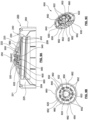
- Figures 5A, 5B, and 5C show one embodiment of various parts of a closure according to the present invention.
- Figure 5A shows a cross-section through an embodiment with a base element 200, when (outer) skirt portion 260 and an inner skirt portion 240, having an inner thread 242, wherein one embodiment of the second flow control element 600 is attached to the first flow control element 300, also in this embodiment by snap fitting, as explained in connection with figure 3 and figure 4 .
- Figures 5A and 5B show one embodiment of a second flow control element 600, having a circular form and having an inner, circular opening 620 as well as an outer circular edge portion 660, which extends, in an assembled position, towards an inner side of the deck portion 220.
- the second flow control element 600 further comprises three extension 622 being positioned around the central opening 620 and extending, in its assembled position, towards the deck portion 220 or the dispensing channel 251, partly covering voids generated by the plate element 350 and the rack elements 320 and the deck portion 220, while still keeping at least one of the voids or at least parts of one the voids or of multiple or all voids open for allowing a liquid to pass therethrough.
- first flow control element 300 and/or the base element 200 and/or the second flow control element 600 are arranged such that the relative angular position between first and second flow control element is fixed.
- the second flow control element 600 also comprises three fins 630, extending in a radial direction and on an inner side or surface of the ringlike plate portion 640 from the inner opening 620 to the outer edge portion 660. These fins 630 are arranged in equal angular distances, one every 120°. The fins 630 both increase stability of the second flow control element 600 and also influence the flow of liquid or the direction of flow of liquid. This can be well seen in figure 5A , which shows a cross-section through the second flow control element 600, on the right side through one of the fins 630, on the left side at a portion where no fin is provided.
- the void in this cross-sectional plane shown in figure 5A through which the fluid can flow is, between the second flow control element 600 and the ringlike extension 222, extending from the deck portion 200 towards the second flow control element 600, remarkably smaller in those areas where a fin is provided (right side) in those areas where no fin is provided (left side). Therefore, not only the direction of flow of liquid is changed during the dispensing process, but the flow properties are different depending on the angular position of the second flow control element or the base element respectively.
- the height of the ringlike extension 222, extending downwardly from the deck portion 220, in this case from the dome-shaped portion 223, and the height of the edge portion 660 are selected such that the edge portion 660 on the one hand and the ringlike extension 222 on the other hand flush with each other or partly overlap each other in a height direction or in a vertical direction. This increases the effect of changing the direction of the flow of liquid when being dispensed.
- Figures 6A, 6B, and 6C show another embodiment of parts of the closure according to the present invention. This embodiment is very similar to the embodiment shown in figures 5A, 5B, and 5C , so that it is referred to the above description order to avoid repetitions. It also has to be noted that the same or similar elements are designated by the same reference numerals.
- the embodiment shown in figures 6A, 6B, and 6C differs from the embodiment shown in figures 5A, 5B, and 5C by a different, here lower height of the edge portion 660 and a lower height of the fins 630.
- the edge portion 660 does not overlap in a height direction or a vertical direction with the ringlike extension 222, thereby leading to a different flow control of the liquid to be dispensed.
- FIGS 7A, 7B, and 7C show still another embodiment of parts of the closure according to the present invention. This embodiment is very similar to the embodiment shown in the earlier figures, so that it is referred to the above description order to avoid repetitions. It also has to be noted that the same or similar elements are designated by the same reference numerals.
- the second flow control element 600 comprises an additional ringlike extension 650, extending, in its final and assembled position, towards the deck portion 220 of the base element, while the ringlike extension 650 is provided between the outer edge portion 660 and the inner opening 620.
- the flow control of the liquid to be dispensed is different from both above-mentioned embodiments, and there will be an even further increase of change of flow direction and/or mixture and/or homogenization of liquid to be dispensed during the dispensing process.
- this additional ringlike extension 650 can be also very well applied to the embodiment shown in figure 5 .
- FIGS 8A, 8B, and 8C show still another embodiment of parts of the closure according to the present invention. This embodiment is very similar to the embodiment shown in the earlier figures, so that it is referred to the above description order to avoid repetitions. It also has to be noted that the same or similar elements are designated by the same reference numerals.
- the second flow control element 600 comprises a ringlike extension 650, which, however, is not provided continuously, but interrupted with gaps 652, being provided around the circumference in equal angular distances.
- gaps 652 are not provided continuously, but interrupted with gaps 652, being provided around the circumference in equal angular distances.
- the number of gaps 652 and its size as well as its positions can be adapted.
- FIGS 9A, 9B, and 9C show still another embodiment of parts of the closure according to the present invention. This embodiment is very similar to the embodiment shown in the earlier figures, so that it is referred to the above description order to avoid repetitions. It also has to be noted that the same or similar elements are designated by the same reference numerals.
- This embodiment is very similar to the embodiment shown in figures 8A, 8B, and 8C , however in this embodiment also the outer edge portion 660 comprises various gaps 662 positions around the circumference in equal angular distances.
- the height of the outer edge portion 660 and of the ringlike extension 650 are different, namely higher in the embodiment as shown in figure 9 .
- the embodiment as shown in figure 9 therefore leads to a more intensive influence and change of the flow direction and/or the mixture and/or the homogenization of liquid to be dispensed during the dispensing process.
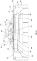
- Figure 10 shows a cross-section is to another embodiment of the closure according to the present invention. This embodiment is very similar to the embodiment shown in the earlier figures, so that it is referred to the above description order to avoid repetitions. It also has to be noted that the same or similar elements are designated by the same reference numerals.
- the base element 200 also comprises a liner 900, which is positioned at the ringlike inner surface 209. As one can well see the liner 900 extends over the complete cross-section and within the circumferential borders as defined by the skirt 240. In this specific embodiment the liner and the cross-section of the inner part of the base element 200 and especially the skirt 240 are arranged such that the liner 900 is hold or clamped in this position. Especially the inner thread 242 secures that the liner 900 is hold in a position at or in the vicinity of the flat surface 209 and that the liner 900 cannot fall out.
- the design and structure of the closure according to the present invention is very suitable for providing such a liner, especially as the structure can be realized within a very small space and/or height, so that especially the height of the closure can be kept very small.
- the first and second flow control elements can be fully covered within a space defined by the dome-shaped section 223, therefore closures with a very reduced or small height can be realized, which is a remarkable advantage both for the user and with respect to manufacturing costs.
- the liner 900 is backed and/or protected by a lower surface of the second flow control element 660, which avoids or at least limits the risk of an undesired or unintentional damage of the liner, especially during transport of the closure and before the closure has been attached to a container.
- the liner 900 is at least partly in contact with the second flow control element 600, but in another embodiment it can be in full contact with an outer surface of the second flow control element 600, while in other embodiments there may be a small distance between the liner 900 and the second flow control element 600, with the distance being preferably very small, preferably at maximum 2 mm or at maximum 1 mm or more preferably at maximum 0.5 mm.
- Figure 11 shows a further embodiment of a second flow control member 600 which can be used in a dispensing closure according to the present invention.
- Figure 11A shows a perspective view
- figure 11B shows a view from the lower side
- figure 11C shows a cross-section of the second flow control member 600.
- This embodiment of a second flow control member 600 is very similar to the flow control members of the embodiments shown in the earlier figures, so that it is referred to the above description in order to avoid repetitions. It also has to be noted that the same or similar elements are designated by the same reference numerals.
- This embodiment of the second flow control member 600 is especially comparable with and similar to the embodiment shown in figure 9 , however the outer edge portion 660 is not provided continuously around the complete circumference, but there are gaps 662 provided in between, in equal angular distances. Such gaps 662 in the outer edge portion 660 are also provided an embodiment as shown in figure 9 , however in this embodiment of figure 11 the gaps are not square like, but the outer edge portion continuously changes its height, with slanted surfaces 661. In this embodiment, there are altogether 5 gaps provided.
- the second flow control member 600 according to the embodiment shown in figure 11 does not have an additional ringlike extension (see 650 in figure 9 or also the embodiment shown in figure 7 ).
- the second flow control member 600 is not completely flat at its lower side or its downside, that is, also at the lower side or under side, curved. This saves material and therefore costs and also has a positive influence on the flow of liquid.
- Figure 12 shows a still further embodiment of a second flow control member 600 which can be used in a dispensing closure according to the present invention.
- Figure 12A shows a perspective view
- figure 12B shows a view from the lower side
- figure 12C shows a cross-section of the second flow control member 600.
- This embodiment of a second flow control member 600 is very similar to the flow control members of the embodiments shown in the earlier figures, so that it is referred to the above description in order to avoid repetitions. It also has to be noted that the same or similar elements are designated by the same reference numerals.
- This embodiment of the second flow control member 600 shown in Fig. 12 is comparable to and very similar to the embodiment shown in figure 11 , however, the edge portion 660 has a radial extension or width being larger than in the embodiment shown in figure 11 , especially the edge portion 660 is extending further towards the inner area and the inner opening of the second flow control member 600.
- the larger extension into the radial direction can be especially seen when comparing figure 12C with figure 11C .
- Figure 13 shows a further embodiment of a dispensing closure according to the present invention. This embodiment is similar to the embodiments shown in the earlier figures, so that it is referred to the above description order to avoid repetitions. It also has to be noted that the same or similar elements are designated by the same reference numerals.
- the second flow control member 600 does not have an inner opening (see e.g. 620 in figure 3 and in figure 4 ) and therefore has an essentially flat lower surface.
- the second flow control member 600 is, in this embodiment, also not connected to the first flow control member 300, but connected to the base element, more precisely to a ringlike extension 222 of the base element 200 which projects from the dome-shaped portion 223 of the deck portion 220 in a downward direction.
- the ringlike extension 222 has various protrusions 201 extending in a radial outward direction, in this embodiment altogether four protrusions 201, and the outer edge portion 660 of the second flow control member 600 has corresponding protrusions 601, extending in an inward direction.
- the second flow control member 600 can be connected to the deck 220 of the base element 200 by snap fitting, however not via or directly to the first flow control member 300.
- the cross-section shown in figure 13 is along an angular position in which, on both sides, protrusions 201 and 601 are present, while at other angular positions (not shown in this cross-section) no protrusions are provided, especially in order to allow flow of liquid through voids being created between the second flow control element 600 and other elements of the base element 200, notably between the second flow control element 600 and the ringlike extension 222.
- a connection of the second flow control element 600 especially a connection by snap fitting, but also by other means can be realized by various means, without deviating from the disclosure content of this application.
- the deck portion 220 has, at positions in the vicinity of the outer edge portion 660 of the second flow control element 600, indentations or a channel 820, which serves as voids and which enable both flow of liquid to be dispensed and flow of air, e.g. flow of air streaming from the outside into the container after dispensing a fluid out of the container, also or especially at those angular positions where the protrusions 201 and 601 are present.
- the indentations or channel 820 are ringlike, and the ringlike channel 820 extends through all angular positions, however, in other embodiment, the indentations or channels 820 may be provided only at those angular positions where the protrusions 21 and 601 present.
- the plate 340 of the first flow control element 300 which in this embodiment extends parallel or essentially parallel to a lower extension or plane of the second flow control element 600, could be omitted in another embodiment.
- the rack elements 320 could preferably be further extended into a downward direction, in a preferred embodiment closer to the second flow control element 600.
- the rack elements 320 are even extended until being in contact with the second flow control element 600.
- Respective voids are, in such a specific embodiment, generated or provided between the rack elements 320, the deck portion 220 and the second flow control element 600.
- the base element of the embodiment shown in figure 13 also comprises not only a ringlike flat surface 209 but also a liner 900 being positioned at and/or attached thereto.
- the liner 900 is well supported not only by the flat surface 209, but also by the lower surface of the second control element 600, which provides an additional support and thereby protection of the liner 900, avoiding or at least lowering the risk of undesired or unintentional damage of the liner 900, especially during manufacturing and during transport of the closure, especially before the closure has been attached to a container.
Landscapes
- Engineering & Computer Science (AREA)
- Mechanical Engineering (AREA)
- Closures For Containers (AREA)
Priority Applications (5)
| Application Number | Priority Date | Filing Date | Title |
|---|---|---|---|
| EP23169564.4A EP4455041B1 (de) | 2023-04-24 | 2023-04-24 | Verschluss für einen behälter und behälter mit einem solchen verschluss |
| EP24722131.0A EP4701953A1 (de) | 2023-04-24 | 2024-04-22 | Verschluss für einen behälter und behälter mit einem solchen verschluss |
| CN202480026686.3A CN120981401A (zh) | 2023-04-24 | 2024-04-22 | 用于容器的封闭件和具有这种封闭件的容器 |
| PCT/EP2024/060913 WO2024223475A1 (en) | 2023-04-24 | 2024-04-22 | Closure for a container and container with such a closure |
| MX2025012567A MX2025012567A (es) | 2023-04-24 | 2025-10-21 | Cierre para un contenedor y contenedor con dicho cierre |
Applications Claiming Priority (1)
| Application Number | Priority Date | Filing Date | Title |
|---|---|---|---|
| EP23169564.4A EP4455041B1 (de) | 2023-04-24 | 2023-04-24 | Verschluss für einen behälter und behälter mit einem solchen verschluss |
Publications (2)
| Publication Number | Publication Date |
|---|---|
| EP4455041A1 true EP4455041A1 (de) | 2024-10-30 |
| EP4455041B1 EP4455041B1 (de) | 2026-02-25 |
Family
ID=86185158
Family Applications (2)
| Application Number | Title | Priority Date | Filing Date |
|---|---|---|---|
| EP23169564.4A Active EP4455041B1 (de) | 2023-04-24 | 2023-04-24 | Verschluss für einen behälter und behälter mit einem solchen verschluss |
| EP24722131.0A Pending EP4701953A1 (de) | 2023-04-24 | 2024-04-22 | Verschluss für einen behälter und behälter mit einem solchen verschluss |
Family Applications After (1)
| Application Number | Title | Priority Date | Filing Date |
|---|---|---|---|
| EP24722131.0A Pending EP4701953A1 (de) | 2023-04-24 | 2024-04-22 | Verschluss für einen behälter und behälter mit einem solchen verschluss |
Country Status (4)
| Country | Link |
|---|---|
| EP (2) | EP4455041B1 (de) |
| CN (1) | CN120981401A (de) |
| MX (1) | MX2025012567A (de) |
| WO (1) | WO2024223475A1 (de) |
Citations (5)
| Publication number | Priority date | Publication date | Assignee | Title |
|---|---|---|---|---|
| EP0391688A1 (de) * | 1989-04-06 | 1990-10-10 | Unilever Plc | Flüssigkeits-Abgabevorrichtung |
| WO2000006460A1 (de) * | 1998-07-30 | 2000-02-10 | Seaquist-Löffler Kunststoffwerk Gmbh & Co. Kg | Ventilvorrichtung für einen behälter |
| WO2008015505A1 (en) * | 2006-08-04 | 2008-02-07 | Mrp Medical Research & Promotion Establishment | Bottle for containing fluids, particularly for pharmaceutical products or the like |
| US20210069734A1 (en) * | 2018-05-17 | 2021-03-11 | Alpla Werke Alwin Lehner Gmbh & Co. Kg | Spray attachment for bringing out fluid substances in a jet-like manner |
| EP3752432B1 (de) | 2018-12-21 | 2022-09-21 | H.J. Heinz Company Brands LLC | Behälter, verschluss und verfahren zur herstellung |
-
2023
- 2023-04-24 EP EP23169564.4A patent/EP4455041B1/de active Active
-
2024
- 2024-04-22 WO PCT/EP2024/060913 patent/WO2024223475A1/en not_active Ceased
- 2024-04-22 CN CN202480026686.3A patent/CN120981401A/zh active Pending
- 2024-04-22 EP EP24722131.0A patent/EP4701953A1/de active Pending
-
2025
- 2025-10-21 MX MX2025012567A patent/MX2025012567A/es unknown
Patent Citations (5)
| Publication number | Priority date | Publication date | Assignee | Title |
|---|---|---|---|---|
| EP0391688A1 (de) * | 1989-04-06 | 1990-10-10 | Unilever Plc | Flüssigkeits-Abgabevorrichtung |
| WO2000006460A1 (de) * | 1998-07-30 | 2000-02-10 | Seaquist-Löffler Kunststoffwerk Gmbh & Co. Kg | Ventilvorrichtung für einen behälter |
| WO2008015505A1 (en) * | 2006-08-04 | 2008-02-07 | Mrp Medical Research & Promotion Establishment | Bottle for containing fluids, particularly for pharmaceutical products or the like |
| US20210069734A1 (en) * | 2018-05-17 | 2021-03-11 | Alpla Werke Alwin Lehner Gmbh & Co. Kg | Spray attachment for bringing out fluid substances in a jet-like manner |
| EP3752432B1 (de) | 2018-12-21 | 2022-09-21 | H.J. Heinz Company Brands LLC | Behälter, verschluss und verfahren zur herstellung |
Also Published As
| Publication number | Publication date |
|---|---|
| MX2025012567A (es) | 2025-11-03 |
| WO2024223475A1 (en) | 2024-10-31 |
| EP4455041B1 (de) | 2026-02-25 |
| EP4701953A1 (de) | 2026-03-04 |
| CN120981401A (zh) | 2025-11-18 |
Similar Documents
| Publication | Publication Date | Title |
|---|---|---|
| US11964801B1 (en) | Closure for a container and container with such a closure | |
| US20210002044A1 (en) | Closure for a container and container with such a closure | |
| RU2493075C2 (ru) | Укупорочное устройство с крышкой, уменьшающей утечку | |
| EP2844610B1 (de) | Behälterverschluss für einen entlüfteten giesstrog einer länglichen öffnung | |
| CA2657685C (en) | Dispensing system with a dispensing valve having a projecting, reduced size discharge end | |
| US8523025B2 (en) | Dispensing closure having flow modulator and syneresis capture | |
| CN121134169A (zh) | 两件式液滴分配封闭件 | |
| US8215506B2 (en) | Flip top closure assembly for a bottle | |
| US5467879A (en) | Linerless closure and fitment assembly | |
| US20070295764A1 (en) | Flexible, elongate dispensing valve | |
| EP4455041A1 (de) | Verschluss für einen behälter und behälter mit einem solchen verschluss | |
| EP4370435A1 (de) | Scharnierverschluss mit ausrichtungsrippe | |
| US20080210709A1 (en) | Rotatable, Reclosable Closure | |
| US20080283485A1 (en) | Dispensing Caps for Liquid Containers | |
| US7000808B2 (en) | Spout design | |
| JP2021008290A (ja) | 容器用キャップ | |
| US2839230A (en) | Dispensing nozzle with non-drip collar | |
| US1279487A (en) | Squirt-can. | |
| US7182230B2 (en) | Resealable closure system | |
| US12077356B2 (en) | Dispensing system | |
| US20250091774A1 (en) | Fluid storage and dispensing container and lid for fluid storage and dispensing container | |
| US20250033841A1 (en) | Container, closure, and methods of manufacture and use | |
| EP4519175A1 (de) | Verschluss, behälter und anordnung dafür | |
| JP2025103249A (ja) | 注出栓付き容器 | |
| CN118922357A (zh) | 容器盖及与其结合的容器 |
Legal Events
| Date | Code | Title | Description |
|---|---|---|---|
| PUAI | Public reference made under article 153(3) epc to a published international application that has entered the european phase |
Free format text: ORIGINAL CODE: 0009012 |
|
| STAA | Information on the status of an ep patent application or granted ep patent |
Free format text: STATUS: THE APPLICATION HAS BEEN PUBLISHED |
|
| AK | Designated contracting states |
Kind code of ref document: A1 Designated state(s): AL AT BE BG CH CY CZ DE DK EE ES FI FR GB GR HR HU IE IS IT LI LT LU LV MC ME MK MT NL NO PL PT RO RS SE SI SK SM TR |
|
| STAA | Information on the status of an ep patent application or granted ep patent |
Free format text: STATUS: REQUEST FOR EXAMINATION WAS MADE |
|
| GRAP | Despatch of communication of intention to grant a patent |
Free format text: ORIGINAL CODE: EPIDOSNIGR1 |
|
| STAA | Information on the status of an ep patent application or granted ep patent |
Free format text: STATUS: GRANT OF PATENT IS INTENDED |
|
| 17P | Request for examination filed |
Effective date: 20250429 |
|
| TPAC | Observations filed by third parties |
Free format text: ORIGINAL CODE: EPIDOSNTIPA |
|
| GRAJ | Information related to disapproval of communication of intention to grant by the applicant or resumption of examination proceedings by the epo deleted |
Free format text: ORIGINAL CODE: EPIDOSDIGR1 |
|
| GRAP | Despatch of communication of intention to grant a patent |
Free format text: ORIGINAL CODE: EPIDOSNIGR1 |
|
| STAA | Information on the status of an ep patent application or granted ep patent |
Free format text: STATUS: REQUEST FOR EXAMINATION WAS MADE |
|
| INTG | Intention to grant announced |
Effective date: 20250602 |
|
| GRAJ | Information related to disapproval of communication of intention to grant by the applicant or resumption of examination proceedings by the epo deleted |
Free format text: ORIGINAL CODE: EPIDOSDIGR1 |
|
| TPAC | Observations filed by third parties |
Free format text: ORIGINAL CODE: EPIDOSNTIPA |
|
| INTC | Intention to grant announced (deleted) | ||
| GRAP | Despatch of communication of intention to grant a patent |
Free format text: ORIGINAL CODE: EPIDOSNIGR1 |
|
| STAA | Information on the status of an ep patent application or granted ep patent |
Free format text: STATUS: GRANT OF PATENT IS INTENDED |
|
| INTC | Intention to grant announced (deleted) | ||
| GRAJ | Information related to disapproval of communication of intention to grant by the applicant or resumption of examination proceedings by the epo deleted |
Free format text: ORIGINAL CODE: EPIDOSDIGR1 |
|
| STAA | Information on the status of an ep patent application or granted ep patent |
Free format text: STATUS: REQUEST FOR EXAMINATION WAS MADE |
|
| TPAC | Observations filed by third parties |
Free format text: ORIGINAL CODE: EPIDOSNTIPA |
|
| INTG | Intention to grant announced |
Effective date: 20250902 |
|
| INTC | Intention to grant announced (deleted) | ||
| GRAP | Despatch of communication of intention to grant a patent |
Free format text: ORIGINAL CODE: EPIDOSNIGR1 |
|
| STAA | Information on the status of an ep patent application or granted ep patent |
Free format text: STATUS: GRANT OF PATENT IS INTENDED |
|
| INTG | Intention to grant announced |
Effective date: 20251031 |
|
| GRAS | Grant fee paid |
Free format text: ORIGINAL CODE: EPIDOSNIGR3 |
|
| GRAA | (expected) grant |
Free format text: ORIGINAL CODE: 0009210 |
|
| STAA | Information on the status of an ep patent application or granted ep patent |
Free format text: STATUS: THE PATENT HAS BEEN GRANTED |
|
| P01 | Opt-out of the competence of the unified patent court (upc) registered |
Free format text: CASE NUMBER: UPC_APP_0019335_4455041/2025 Effective date: 20251223 |
|
| AK | Designated contracting states |
Kind code of ref document: B1 Designated state(s): AL AT BE BG CH CY CZ DE DK EE ES FI FR GB GR HR HU IE IS IT LI LT LU LV MC ME MK MT NL NO PL PT RO RS SE SI SK SM TR |
|
| REG | Reference to a national code |
Ref country code: CH Ref legal event code: F10 Free format text: ST27 STATUS EVENT CODE: U-0-0-F10-F00 (AS PROVIDED BY THE NATIONAL OFFICE) Effective date: 20260225 Ref country code: GB Ref legal event code: FG4D |
|
| REG | Reference to a national code |
Ref country code: DE Ref legal event code: R096 Ref document number: 602023012428 Country of ref document: DE |
|
| REG | Reference to a national code |
Ref country code: IE Ref legal event code: FG4D |