EP4455107A1 - Verfahren zum brennen von carbonisierten mineralsteinen in einem ringförmigen vertikalen ofen und implementierter ofen - Google Patents
Verfahren zum brennen von carbonisierten mineralsteinen in einem ringförmigen vertikalen ofen und implementierter ofen Download PDFInfo
- Publication number
- EP4455107A1 EP4455107A1 EP23170424.8A EP23170424A EP4455107A1 EP 4455107 A1 EP4455107 A1 EP 4455107A1 EP 23170424 A EP23170424 A EP 23170424A EP 4455107 A1 EP4455107 A1 EP 4455107A1
- Authority
- EP
- European Patent Office
- Prior art keywords
- gas
- heated
- kiln
- plasma torch
- cooling air
- Prior art date
- Legal status (The legal status is an assumption and is not a legal conclusion. Google has not performed a legal analysis and makes no representation as to the accuracy of the status listed.)
- Withdrawn
Links
Images

Classifications
-
- C—CHEMISTRY; METALLURGY
- C04—CEMENTS; CONCRETE; ARTIFICIAL STONE; CERAMICS; REFRACTORIES
- C04B—LIME, MAGNESIA; SLAG; CEMENTS; COMPOSITIONS THEREOF, e.g. MORTARS, CONCRETE OR LIKE BUILDING MATERIALS; ARTIFICIAL STONE; CERAMICS; REFRACTORIES; TREATMENT OF NATURAL STONE
- C04B2/00—Lime, magnesia or dolomite
- C04B2/10—Preheating, burning calcining or cooling
- C04B2/12—Preheating, burning calcining or cooling in shaft or vertical furnaces
Definitions
- the present invention relates to a process for calcining carbonated mineral stones in an annular shaft kiln (ASK), having an outer cylinder and an inner cylinder forming an annular space between them.
- ASK annular shaft kiln
- carbonated mineral stones particularly mean calcareous stones (limestones), dolomitic stones (dolostones or unburnt dolomites) and/or magnesite stones which are calcined into quicklime, quick dolime and/or magnesia.
- the object of the present invention is to remedy the problems of fuel combustions, particularly fossil fuels, of ASK kilns, without modifying substantially their functioning and by making little or no changes to their structure. Another object is to avoid as much as possible overheat of the calcined material and introduction of impurities in this material and in the gaseous effluent exiting from the kiln.
- the main object of the calcination kilns must obviously be maintained, i.e. the production of a calcined material of high quality and purity.
- a method as above indicated further comprises a first heating step of a gas by means of at least one plasma torch for producing a lower heated gas, and a first step for mixing said lower heated gas with a control gas which is not heated by the at least one plasma torch for controlling a temperature of a first gaseous mixture which is said lower hot gas injected into the kiln at the second level of the annular space, the controlled temperature allowing a calcining of the carbonated mineral stones.
- the invention relies mostly on externalizing the energy supply while heating a gas with a plasma torch, particularly at the second level of the kiln.
- the heated gas is partially broken down at high temperature in an electric arc, but mostly recombined in the process.
- the lower heated gas which is heated by at least one plasma torch is selected among the group consisting of air, N 2 , CO 2 , steam, noble gas and their mixtures and the control gas is comprised of recirculated gaseous stream containing said heated cooling air or b) the lower heated gas which is heated by at least one plasma torch is comprised of recirculated gaseous stream containing said heated cooling air and the control gas is selected among the group consisting of air, N 2 , CO 2 , steam, and their mixtures or c) the lower heated gas which is heated by at least one plasma torch as well as the control gas are comprised of recirculated gaseous stream containing said heated cooling air.
- air and/or water is additionally introduced in the at least one plasma torch and /or mixed in the first gaseous mixture.
- the process comprises a second heating step of a gas by means of at least one additional plasma torch for producing an upper heated gas, and a second step for mixing said upper heated gas with an adjusting gas which is not heated by the at least one additional plasma torch for adjusting a temperature of a second gaseous mixture which is said upper hot gas introduced at the first level of the annular space, the adjusted temperature allowing a calcining of the carbonated mineral stones.
- No fuel is still necessary for a combustion inside the kiln. The process does not more necessitate any consumption of fossil fuel.
- the internal cylinder of the kiln has a shell and the process comprises a step of cooling said shell by secondary air and extracting heated secondary air from the kiln.
- the upper heated gas which is heated by at least one additional plasma torch in the second heating step is selected among the group consisting of air, N 2 , CO 2 , steam, noble gas and their mixtures and the adjusting gas is comprised of said heated secondary air or b) the upper heated gas which is heated by at least one additional plasma torch is comprised of said heated secondary air and the adjusting gas is selected among the group consisting of air, N 2 , CO 2 , steam, and their mixtures or c) the upper heated gas which is heated by at least one additional plasma torch as well as the adjusting gas are comprised of said heated secondary air.
- a gas selected among the group consisting of air, N 2 , CO 2 , steam, noble gas and their mixtures is heated in presence of said heated secondary air and an adjusting gas is additionally injected in the corresponding upper mixing chamber.
- air and/or water is additionally introduced in the at least one plasma torch and /or mixed in the second gaseous mixture.
- said upwards draft and said aspiration of the aspiration step are so equilibrated that a first part of the lower hot gas introduced into the annular space is upwards drawn in counter-current of the stones to calcine and a second part of the lower hot gas is supplied downward the bottom of the annular space, in co-current with the mineral stones to calcine, and thereafter aspired inside the inner cylinder, while forming with said cooling air and CO 2 from the decarbonation in the co-current calcination zone said gaseous stream containing said heated cooling air.
- said upwards draft and said aspiration of the aspiration step are so equilibrated that the totality of the lower hot gas introduced into the annular space is submitted to the upwards draft, the gaseous stream aspired in the inner cylinder comprising only cooling air.
- said lower and upper hot gas which are drawn toward the top of the kiln form a gaseous stream which is partially recovered out of the kiln before the exhaust of the gaseous effluent at the top of the kiln and the process further comprises a heat exchange between this recovered gaseous stream and a gas to recirculate towards said first heating step.
- the present invention concerns also an annular shaft kiln for calcining carbonated mineral stones.
- a kiln for calcining carbonated mineral stones.
- such a kiln is equipped with at least one plasma torch for heating a gas and with, as lower gas injection means, at least one lower mixing chamber which is connected to the at least one plasma torch and wherein the heated gas is mixed with a control gas for providing a gaseous mixture which is said lower hot gas to inject having a controlled temperature equal or higher than the temperature of calcination of the loaded mineral stones.
- the at least one lower mixing chamber is connected to the at least one plasma torch which is supplied from an external gas source and to said means for recirculating said gaseous stream containing the heated cooling air, said gas heated by said at least one plasma torch being mixed in said at least one lower mixing chamber with recirculated gaseous stream containing the heated cooling air as control gas, for providing said lower hot gas to inject having a controlled temperature equal or higher than the temperature of calcination of the loaded mineral stones or
- the at least one lower mixing chamber is connected to an external gas source, for providing control gas, and to the at least one plasma torch which is connected to said means for recirculating said gaseous stream containing heated cooling air, said control gas being mixed in said at least one lower mixing chamber with said recirculated gaseous stream heated by the at least plasma torch, for providing said lower hot gas to inject having a controlled temperature equal or higher than the temperature of calcination of the loaded mineral stones or
- the at least one lower mixing chamber is connected to an external gas source, for providing control gas, and to the at least
- the kiln of the invention is equipped with at least one additional plasma torch for heating a gas and with, as upper gas injection means, at least one upper mixing chamber which is connected to the at least one additional plasma torch and wherein the heated gas is mixed with an adjusting gas which has not been heated by the at least one additional plasma torch for providing a gaseous mixture which is said upper hot gas to inject having an adjusted temperature allowing a calcining of the loaded mineral stones.
- the kiln comprises inlet means for secondary cooling air which are connected with the interior of a shell of the inner cylinder, and outlet means able to extract the heated secondary cooling air out of the kiln.
- the at least one upper mixing chamber is connected to the at least one additional plasma torch which is supplied from an external gas source and to said outlet means able to extract said heated secondary cooling air, said gas heated by said at least one additional plasma torch being mixed in said at least one upper mixing chamber with said heated secondary cooling air as adjusting gas, for providing said upper hot gas to inject having an adjusted temperature equal or higher than the temperature of calcining of the loaded mineral stones or
- the at least one upper mixing chamber is connected to an external gas source, for providing an adjusting gas, and to the at least one additional plasma torch which is connected to said outlet means able to extract the heated secondary cooling air, said adjusting gas being mixed in said at least one upper mixing chamber with said heated secondary cooling air heated by the at least one additional plasma torch, for providing said upper hot gas to inject having an adjusted temperature equal or higher than the temperature of preheating of the loaded mineral stones or
- the at least one upper mixing chamber is connected to the at least one additional plasma torch and to said outlet means able to extract said heated secondary cooling air, said gas heated by said at least one additional plasma torch
- the at least one upper mixing chamber is connected, on the one hand, to the at least one additional plasma torch which is supplied with a gas to heat from an external gas source in presence of the heated secondary cooling air extracted by means of said outlet means and, on the other hand, to an external gas source for providing an adjustment of the temperature of the heated gas issuing from the additional plasma torch.
- the invention concerns also a method for revamping a conventional annular shaft kiln for manufacturing an annular shaft kiln according to the present invention.
- Such a method comprises the following steps :
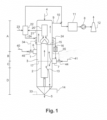
- the kiln illustrated on Fig. 1 comprises an outer cylinder 1 and an inner cylinder 2 which form an annular space 3 wherein carbonated mineral stones descend by gravity. The stones are introduced at the top of the kiln at the material inlet 4 and a decarbonated calcined material is collected by the discharge 5.
- the fuel fumes are injected at two levels by means of burners arranged in combustion chambers 6 and 7 ( 4 to 6 combustion chambers at each level according to the kiln capacity).
- the totality of the fumes of the chambers 6 and a part of the fumes of the chambers 7 are drawn upwards by a fan 8, i.e. in countercurrent of the displacement of the material to calcine. They form of a gaseous effluent which is exhausted from the kiln by the upper outlet 9 , the removal duct 10, a treatment unit 11 and a stack 12. So the descending stones are preheated by heat exchange in the preheating zone A and calcined in a countercurrent calcination zone B.
- the other part of the hot gas issued from the lower combustion chambers 7 is aspired toward the bottom of the kiln by a reduced pressure provided at return vents 13 arranged in the inner cylinder at a level lower than the combustion chambers 7. In this zone C a co-current calcination of the stones takes place.
- a cooling air inlet 14 is provided at the bottom of the annular space.
- the cooling air flows in counter-current of the decarbonated calcined material in a cooling zone D wherein it is so progressively heated.
- a gaseous stream containing the cooling air heated in contact with the decarbonated calcined material and the part of the lower hot gas aspired toward the bottom is sucked from the annular space 3 to the inner cylinder 2.
- the gaseous stream containing the heated cooling air is extracted from the inner cylinder 2 by means of aspiration means, such as eductors 16 (one eductor for each lower combustion chamber) and is recirculated at the level of the lower combustion chambers 7.
- aspiration means such as eductors 16 (one eductor for each lower combustion chamber) and is recirculated at the level of the lower combustion chambers 7.
- the equilibrium between the draft toward the top and the aspiration toward the bottom is represented by the broken line 17.
- This kiln further comprises an upper cylinder 20 which takes off a fraction of the gaseous effluent flowing to the top. Via a recovering duct 21 this gaseous fraction is introduced in a heat recovering means 22 wherein an heat exchange takes place between the recovered gaseous fraction and a driving air supplied by a feeding duct 23. The heated driving air is supplied via transfer ducts 24 to the eductors 16 in order to allow their functioning. The cooled fraction of gaseous effluent is removed toward the top of the kiln and the stack.
- the fuel introduced in the combustion chambers 6 and 7 may be a solid fuel, as coke, coal, or a biomass, or a fluidic fuel such as natural gas, hydrogen, and so on.
- the fuel is transferred to the burners 45 of the chambers 6 via supplying ducts 40 and to the burners 44 of the chambers 7 via supplying ducts 41.
- the oxidizer is air.
- this air is the cooling air extracted from the shell of the inner cylinder 2 which is supplied by the feeding duct 33 and is progressively heated during its climb in said shell while being recycled as oxidizer to the burners of the combustion chambers 6 and/or 7 via the recycling ducts 34 and/or 35.
- the oxidizer may be comprised of a mixture of the downwards sucked fumes and of the heated cooling air. By means of the eductors 16 this mixture is extracted from the inner cylinder 2 and recirculated into the combustion chambers 7 via recirculation ducts 15.
- Each eductor 16 works by means of the driving air which is supplied by the feeding duct 23, heated in the heat recovering unit 22 and thereafter furnished to the eductors 16 by means of the transfer ducts 24.
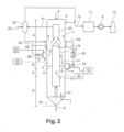
- the kiln according to the invention illustrated on Fig.2 is very similar to the kiln of the Fig.1 .
- the main difference is that there is no more combustion of fuel, and particularly in the chambers 6 and 7.
- These chambers are now simply provided for mixing gas which are injected in the kiln under the form of a gas mixture at a controlled temperature for allowing a calcining of the stones. Here no more burners are necessary.
- These chambers (combustion chambers 6 and 7 in the kiln of Fig.1 ) become now mixing chambers 6' and 7' in the kiln according to the invention.
- Upper gas injection means under the form of upper mixing chambers 6' are provided at a first level of the annular space for injecting into the annular space an upper hot gas.
- Lower gas injection means under the form of lower mixing chambers 7' are provided at a second level of the annular space lower than the level of the chambers 6' for injecting a lower hot gas.
- Hot gas is thus injected at two levels by means of several mixing chambers 6' and 7' (4 to 6 chambers at each level according the capacity of the kiln).
- 1/3 of the hot gas is injected in the annular space by means of the mixing chambers 6' and 2/3 by means of the mixing chambers 7'.
- the kiln of Fig.2 is divided in the same zones A, B, C, D and the displacement of the material to calcine and of the gaseous streams is identical to the kiln of Fig.1 at the difference that the gaseous streams do not contain any fuel combustion fumes.
- cooling air inlet 14 is provided at the bottom of the annular space.
- a gaseous stream containing the cooling air heated in contact with the decarbonated calcined material and the part of the lower hot gas aspired toward the bottom is sucked from the annular space 3 to the inner cylinder 2.
- the gaseous stream containing the heated cooling air is extracted from the inner cylinder 2 by means of aspiration means, such as eductors 16 (one eductor for each lower mixing chamber), and is recirculated at the level of the lower mixing chambers 7'.
- aspiration means such as eductors 16 (one eductor for each lower mixing chamber)
- the kiln of the invention is equipped with several lower plasma torches 18 (4 to 6 according to the capacity of the kiln) able to heat a gas.
- the heated gas is mixed with a control gas for providing a gaseous mixture having a controlled temperature equal or higher than the temperature of calcination of the loaded mineral stones.
- the gas to heat may be comprised of the recirculated gaseous stream containing heated cooling air which has been extracted by the ducts 15 and the eductors 16.
- the heated gas is mixed with a control gas issued from a gas source 19 which has not been heated by a plasma torch 18 for providing a gaseous mixture having a controlled temperature which is injected into the annular space.
- a control gas issued from a gas source 19 which has not been heated by a plasma torch 18 for providing a gaseous mixture having a controlled temperature which is injected into the annular space.
- the recirculated gaseous stream may be driven from the eductors directly into the chambers 7', as control gas, and the plasma torch is then supplied from a source 19 of a gas such as air, steam, CO 2 , N 2 .
- Another possibility is to heat a part of the recirculated gaseous stream and to use as control gas another part of the same recirculated stream which has not been heated.
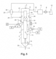
- a supply of water or air may be necessary and is injected in the mixing chamber 7'and/or directly in the plasma torch 18 from a separated source 42 (see Fig.2 and Fig.3 ).
- This kiln further comprises an upper cylinder 20 which takes off a fraction of the gaseous effluent flowing to the top. Via a recovering duct 21 this gaseous fraction is introduced in an heat recovering means 22 wherein an heat exchange takes place between the recovered gaseous fraction and a driving air supplied by a feeding duct 23. The heated driving air is supplied via transfer ducts 24 to the eductors 16 in order to allow their functioning. The cooled fraction of gaseous effluent is removed toward the stack.
- the kiln of Fig.2 is provided with several recirculation ducts 25.
- heated secondary cooling air is extracted from the shell of the inner cylinder 2 and is recirculated at the level of the upper mixing chambers 6'.
- the kiln of Fig.2 is equipped with several upper plasma torches 26 (4 to 6 according to the capacity of the kiln) able to heat a gas and with the upper mixing chambers 6' wherein the heated gas is mixed with an adjusting gas for providing a gaseous mixture having an adjusted temperature appropriate for calcining the loaded mineral stones.
- the gas to heat may be comprised of heated secondary cooling air which, after being heated, is injected into the upper mixing chambers 6'.
- the heated gas is mixed with an adjusting gas issued from a gas source 27, for example an air source, which has not been heated by a plasma torch 26.
- a gas source 27 for example an air source, which has not been heated by a plasma torch 26.
- Other arrangements may be conceived.
- the heated secondary cooling air may be introduced directly into the mixing chambers, as adjusting gas, and the gas to heat by the plasma torches may be supplied from the external gas source 27.
- Another possibility may also be to heat a part of the heated secondary cooling air, as gas to heat by the plasma torches, and to use another part of the heated secondary cooling air, as adjusting gas.
- a supply of water or air may be necessary and is injected in the mixing chamber 6' and/or in the plasma torch 26 from a separated source 43.
- kiln as illustrated on Fig.1 is implemented as in the prior art. Above the working of such a kiln was already disclosed in detail.
- the kiln of this example allows a production of 150 t/day of lime. Limestone is introduced in the kiln by the material inlet 4 and is calcined under the form of quicklime which is collected by the discharge 5.
- Standard burners 45 and 44 are provided on combustion chambers 6 and 7 arranged at two levels of the kiln. As fuel they are supplied with natural gas which is transferred to the burners via supplying ducts 40 and respectively 41. 67 vol % of the fuel are injected in the lower burners 44 and 33 vol% of the fuel in the upper burners 45.
- 800 Nm 3 /t of cooling air are introduced in the kiln by the inlet 14 for cooling the calcined lime in counter-current.
- the heated cooling air is sucked into the inner cylinder 2 with a portion of the fumes issuing from the lower combustion chambers 7 and this gaseous mixture is extracted from the top of the inner cylinder 2 by means of eductors 16.
- 1600 Nm 3 /t of the extracted mixture containing the heated cooling air is so recirculated into the lower combustion chambers 7 at a temperature of 850°C.
- 320 Nm 3 /t of driving air are supplied via transfer ducts 24 to the eductors 16.
- the fuel is burned in presence of 175 Nm 3 /t of an oxidizer which is the secondary air used for cooling the shell of the internal cylinder 2 and is extracted from the kiln by the recycling ducts 35..
- an oxidizer which is the secondary air used for cooling the shell of the internal cylinder 2 and is extracted from the kiln by the recycling ducts 35..
- the temperature of the fumes reaches 1550°C.
- the fuel is burned in presence of 175 Nm 3 /t of an oxidizer which is the secondary air used for cooling the shell of the internal cylinder 2 and is extracted from the kiln by the recycling ducts 34.
- an oxidizer which is the secondary air used for cooling the shell of the internal cylinder 2 and is extracted from the kiln by the recycling ducts 34.
- the temperature of the fumes reaches 1500°C.
- the kiln has a thermal power of 7,5 MWth, i.e. 5 MWth from the lower burners 44 and 2,5 MWth from the upper burners 45.
- each upper burner 45 is replaced by an upper plasma torch 26 and each lower burner 44 is replaced by a lower plasma torch 18. Consequently, there is no more combustion of fuel in the chambers 6 and 7 and now they are called mixing chambers 6' and 7' wherein a gas heated by a plasma torch is mixed with a gas which controls or adjusts the temperature of a gaseous mixture to inject into the kiln.
- the mean temperature of the mixture of the hot gas heated by the plasma torch 18 and of the recirculated gas is of 1420°C. If a higher temperature is necessary in the lower mixing chambers 7', for example of 1550°C, it is possible to reduce the flow of the air issuing from the air source 42 or to adapt the flow of cooling air in the kiln or to apply both solutions.
- the kiln has a thermal power of 8,2 MWth, i.e. 5,5 MWth from the lower plasma torches 18 and 2,7 MWth from the upper plasma torches 26.
- Example 1 a classical kiln, such as disclosed in Example 1, may be transformed in a kiln of the invention, as disclosed in Example 2, in an extremely simple manner, kiln wherein no fossil fuel has to be burned.
Landscapes
- Chemical & Material Sciences (AREA)
- Engineering & Computer Science (AREA)
- Ceramic Engineering (AREA)
- Physics & Mathematics (AREA)
- Thermal Sciences (AREA)
- Materials Engineering (AREA)
- Structural Engineering (AREA)
- Organic Chemistry (AREA)
- Furnace Details (AREA)
Priority Applications (3)
| Application Number | Priority Date | Filing Date | Title |
|---|---|---|---|
| EP23170424.8A EP4455107A1 (de) | 2023-04-27 | 2023-04-27 | Verfahren zum brennen von carbonisierten mineralsteinen in einem ringförmigen vertikalen ofen und implementierter ofen |
| PCT/EP2023/087209 WO2024141398A1 (en) | 2022-12-30 | 2023-12-21 | Process for calcining carbonated mineral stones in an annular vertical kiln and implemented kiln |
| EP23836860.9A EP4642742A1 (de) | 2022-12-30 | 2023-12-21 | Verfahren zum brennen von carbonisierten mineralsteinen in einem ringförmigen vertikalen ofen und implementierter ofen |
Applications Claiming Priority (1)
| Application Number | Priority Date | Filing Date | Title |
|---|---|---|---|
| EP23170424.8A EP4455107A1 (de) | 2023-04-27 | 2023-04-27 | Verfahren zum brennen von carbonisierten mineralsteinen in einem ringförmigen vertikalen ofen und implementierter ofen |
Publications (1)
| Publication Number | Publication Date |
|---|---|
| EP4455107A1 true EP4455107A1 (de) | 2024-10-30 |
Family
ID=86272515
Family Applications (1)
| Application Number | Title | Priority Date | Filing Date |
|---|---|---|---|
| EP23170424.8A Withdrawn EP4455107A1 (de) | 2022-12-30 | 2023-04-27 | Verfahren zum brennen von carbonisierten mineralsteinen in einem ringförmigen vertikalen ofen und implementierter ofen |
Country Status (1)
| Country | Link |
|---|---|
| EP (1) | EP4455107A1 (de) |
Citations (3)
| Publication number | Priority date | Publication date | Assignee | Title |
|---|---|---|---|---|
| US4332641A (en) * | 1980-12-22 | 1982-06-01 | Conoco, Inc. | Process for producing calcined coke and rich synthesis gas |
| US4626200A (en) * | 1985-07-15 | 1986-12-02 | Fuller Company | Shaft kilns having fluid-bed air heater |
| CN204125380U (zh) * | 2014-08-22 | 2015-01-28 | 石家庄新华能源环保科技股份有限公司 | 一种等离子加热生产石灰的装置 |
-
2023
- 2023-04-27 EP EP23170424.8A patent/EP4455107A1/de not_active Withdrawn
Patent Citations (3)
| Publication number | Priority date | Publication date | Assignee | Title |
|---|---|---|---|---|
| US4332641A (en) * | 1980-12-22 | 1982-06-01 | Conoco, Inc. | Process for producing calcined coke and rich synthesis gas |
| US4626200A (en) * | 1985-07-15 | 1986-12-02 | Fuller Company | Shaft kilns having fluid-bed air heater |
| CN204125380U (zh) * | 2014-08-22 | 2015-01-28 | 石家庄新华能源环保科技股份有限公司 | 一种等离子加热生产石灰的装置 |
Similar Documents
| Publication | Publication Date | Title |
|---|---|---|
| CN112105880B (zh) | 具有特殊氧气添加的氧燃料熟料生产 | |
| FI4324799T3 (fi) | Menetelmä mineraalikivien kalsinoimiseksi regeneratiivisessa, samansuuntaisiin virtoihin perustuvassa pystykuilu-uunissa ja käytettävä uuni | |
| CN108675655A (zh) | 一种采用热风的石灰窑装置 | |
| JPH08225347A (ja) | 高温バルク材の冷却方法、焼成バルク材の製造方法及び装置 | |
| CZ299743B6 (cs) | Vypalovací zarízení pro výrobu cementu a zpusob výroby cementu v tomto zarízení | |
| CN107438747A (zh) | 具有减少的污染气体排放的用于生产水泥的设备 | |
| JP2001046861A (ja) | 鉱石系物質のか焼方法 | |
| EP1017958B1 (de) | Verbrennungs-sauerstoffanreicherung in zementofen-systemen | |
| EP4394295A1 (de) | Verfahren zum brennen von carbonisierten mineralsteinen in einem ringförmigen vertikalen ofen und implementierter ofen | |
| EP4455107A1 (de) | Verfahren zum brennen von carbonisierten mineralsteinen in einem ringförmigen vertikalen ofen und implementierter ofen | |
| EP4394296A1 (de) | Verfahren zum kalzinieren von karbonisierten mineralsteinen in einem regenerativen ofen mit parallelem fluss und implementierter ofen | |
| EP4394299A1 (de) | Verfahren zum brennen von carbonisierten mineralsteinen in einem ringförmigen vertikalen ofen und implementierter ofen | |
| EP4642742A1 (de) | Verfahren zum brennen von carbonisierten mineralsteinen in einem ringförmigen vertikalen ofen und implementierter ofen | |
| US4220631A (en) | Process of calcining limestone or hydrated lime in a rotary kiln | |
| EP4394298A1 (de) | Verfahren zum kalzinieren von karbonisierten mineralsteinen in einem regenerativen ofen mit parallelem fluss und implementierter ofen | |
| EP4394297A1 (de) | Verfahren zum kalzinieren von karbonisierten mineralsteinen in einem regenerativen ofen mit parallelem fluss und implementierter ofen | |
| CA3217307A1 (en) | Method and installation for producing lime or dolime | |
| CN208776590U (zh) | 一种采用热风的石灰窑装置 | |
| SU1315478A1 (ru) | Способ обжига сидеритовых руд и шахтна печь дл его осуществлени | |
| CN115893875B (zh) | 一种竖炉石灰窑降低co2排放的方法 | |
| KR100201367B1 (ko) | 애뉼라 샤프트킬른에서의 생석회 증산방법 | |
| EP4303200A1 (de) | Verfahren zum mindestens teilweisen kalzinieren eines rohmaterials in einem verfahren zum produzieren eines zementartigen materials | |
| US20240067563A1 (en) | Apparatus and process for production of burnt lime or dolomite | |
| WO2025242286A1 (en) | Method and kiln for calcining carbonate mineral stones in a parallel flow regenerative kiln (pfrk) | |
| WO2026092854A1 (en) | Method for calcining carbonate mineral stones in a parallel flow regenerative kiln and implemented kiln |
Legal Events
| Date | Code | Title | Description |
|---|---|---|---|
| PUAI | Public reference made under article 153(3) epc to a published international application that has entered the european phase |
Free format text: ORIGINAL CODE: 0009012 |
|
| STAA | Information on the status of an ep patent application or granted ep patent |
Free format text: STATUS: THE APPLICATION HAS BEEN PUBLISHED |
|
| AK | Designated contracting states |
Kind code of ref document: A1 Designated state(s): AL AT BE BG CH CY CZ DE DK EE ES FI FR GB GR HR HU IE IS IT LI LT LU LV MC ME MK MT NL NO PL PT RO RS SE SI SK SM TR |
|
| STAA | Information on the status of an ep patent application or granted ep patent |
Free format text: STATUS: THE APPLICATION IS DEEMED TO BE WITHDRAWN |
|
| 18D | Application deemed to be withdrawn |
Effective date: 20250501 |