EP4455371A2 - Elektrolysezelle und elektrolysevorrichtung - Google Patents
Elektrolysezelle und elektrolysevorrichtung Download PDFInfo
- Publication number
- EP4455371A2 EP4455371A2 EP24163202.5A EP24163202A EP4455371A2 EP 4455371 A2 EP4455371 A2 EP 4455371A2 EP 24163202 A EP24163202 A EP 24163202A EP 4455371 A2 EP4455371 A2 EP 4455371A2
- Authority
- EP
- European Patent Office
- Prior art keywords
- porous membrane
- anode
- cathode
- pore
- cell according
- Prior art date
- Legal status (The legal status is an assumption and is not a legal conclusion. Google has not performed a legal analysis and makes no representation as to the accuracy of the status listed.)
- Pending
Links
Images

Classifications
-
- C—CHEMISTRY; METALLURGY
- C25—ELECTROLYTIC OR ELECTROPHORETIC PROCESSES; APPARATUS THEREFOR
- C25B—ELECTROLYTIC OR ELECTROPHORETIC PROCESSES FOR THE PRODUCTION OF COMPOUNDS OR NON-METALS; APPARATUS THEREFOR
- C25B1/00—Electrolytic production of inorganic compounds or non-metals
- C25B1/01—Products
- C25B1/02—Hydrogen or oxygen
- C25B1/04—Hydrogen or oxygen by electrolysis of water
-
- C—CHEMISTRY; METALLURGY
- C25—ELECTROLYTIC OR ELECTROPHORETIC PROCESSES; APPARATUS THEREFOR
- C25B—ELECTROLYTIC OR ELECTROPHORETIC PROCESSES FOR THE PRODUCTION OF COMPOUNDS OR NON-METALS; APPARATUS THEREFOR
- C25B1/00—Electrolytic production of inorganic compounds or non-metals
- C25B1/01—Products
- C25B1/23—Carbon monoxide or syngas
-
- C—CHEMISTRY; METALLURGY
- C25—ELECTROLYTIC OR ELECTROPHORETIC PROCESSES; APPARATUS THEREFOR
- C25B—ELECTROLYTIC OR ELECTROPHORETIC PROCESSES FOR THE PRODUCTION OF COMPOUNDS OR NON-METALS; APPARATUS THEREFOR
- C25B11/00—Electrodes; Manufacture thereof not otherwise provided for
- C25B11/02—Electrodes; Manufacture thereof not otherwise provided for characterised by shape or form
- C25B11/03—Electrodes; Manufacture thereof not otherwise provided for characterised by shape or form perforated or foraminous
- C25B11/031—Porous electrodes
-
- C—CHEMISTRY; METALLURGY
- C25—ELECTROLYTIC OR ELECTROPHORETIC PROCESSES; APPARATUS THEREFOR
- C25B—ELECTROLYTIC OR ELECTROPHORETIC PROCESSES FOR THE PRODUCTION OF COMPOUNDS OR NON-METALS; APPARATUS THEREFOR
- C25B11/00—Electrodes; Manufacture thereof not otherwise provided for
- C25B11/02—Electrodes; Manufacture thereof not otherwise provided for characterised by shape or form
- C25B11/03—Electrodes; Manufacture thereof not otherwise provided for characterised by shape or form perforated or foraminous
- C25B11/031—Porous electrodes
- C25B11/032—Gas diffusion electrodes
-
- C—CHEMISTRY; METALLURGY
- C25—ELECTROLYTIC OR ELECTROPHORETIC PROCESSES; APPARATUS THEREFOR
- C25B—ELECTROLYTIC OR ELECTROPHORETIC PROCESSES FOR THE PRODUCTION OF COMPOUNDS OR NON-METALS; APPARATUS THEREFOR
- C25B11/00—Electrodes; Manufacture thereof not otherwise provided for
- C25B11/04—Electrodes; Manufacture thereof not otherwise provided for characterised by the material
- C25B11/051—Electrodes formed of electrocatalysts on a substrate or carrier
- C25B11/055—Electrodes formed of electrocatalysts on a substrate or carrier characterised by the substrate or carrier material
- C25B11/057—Electrodes formed of electrocatalysts on a substrate or carrier characterised by the substrate or carrier material consisting of a single element or compound
- C25B11/061—Metal or alloy
-
- C—CHEMISTRY; METALLURGY
- C25—ELECTROLYTIC OR ELECTROPHORETIC PROCESSES; APPARATUS THEREFOR
- C25B—ELECTROLYTIC OR ELECTROPHORETIC PROCESSES FOR THE PRODUCTION OF COMPOUNDS OR NON-METALS; APPARATUS THEREFOR
- C25B11/00—Electrodes; Manufacture thereof not otherwise provided for
- C25B11/04—Electrodes; Manufacture thereof not otherwise provided for characterised by the material
- C25B11/051—Electrodes formed of electrocatalysts on a substrate or carrier
- C25B11/055—Electrodes formed of electrocatalysts on a substrate or carrier characterised by the substrate or carrier material
- C25B11/057—Electrodes formed of electrocatalysts on a substrate or carrier characterised by the substrate or carrier material consisting of a single element or compound
- C25B11/061—Metal or alloy
- C25B11/063—Valve metal, e.g. titanium
-
- C—CHEMISTRY; METALLURGY
- C25—ELECTROLYTIC OR ELECTROPHORETIC PROCESSES; APPARATUS THEREFOR
- C25B—ELECTROLYTIC OR ELECTROPHORETIC PROCESSES FOR THE PRODUCTION OF COMPOUNDS OR NON-METALS; APPARATUS THEREFOR
- C25B11/00—Electrodes; Manufacture thereof not otherwise provided for
- C25B11/04—Electrodes; Manufacture thereof not otherwise provided for characterised by the material
- C25B11/051—Electrodes formed of electrocatalysts on a substrate or carrier
- C25B11/055—Electrodes formed of electrocatalysts on a substrate or carrier characterised by the substrate or carrier material
- C25B11/057—Electrodes formed of electrocatalysts on a substrate or carrier characterised by the substrate or carrier material consisting of a single element or compound
- C25B11/065—Carbon
-
- C—CHEMISTRY; METALLURGY
- C25—ELECTROLYTIC OR ELECTROPHORETIC PROCESSES; APPARATUS THEREFOR
- C25B—ELECTROLYTIC OR ELECTROPHORETIC PROCESSES FOR THE PRODUCTION OF COMPOUNDS OR NON-METALS; APPARATUS THEREFOR
- C25B11/00—Electrodes; Manufacture thereof not otherwise provided for
- C25B11/04—Electrodes; Manufacture thereof not otherwise provided for characterised by the material
- C25B11/051—Electrodes formed of electrocatalysts on a substrate or carrier
- C25B11/073—Electrodes formed of electrocatalysts on a substrate or carrier characterised by the electrocatalyst material
- C25B11/091—Electrodes formed of electrocatalysts on a substrate or carrier characterised by the electrocatalyst material consisting of at least one catalytic element and at least one catalytic compound; consisting of two or more catalytic elements or catalytic compounds
-
- C—CHEMISTRY; METALLURGY
- C25—ELECTROLYTIC OR ELECTROPHORETIC PROCESSES; APPARATUS THEREFOR
- C25B—ELECTROLYTIC OR ELECTROPHORETIC PROCESSES FOR THE PRODUCTION OF COMPOUNDS OR NON-METALS; APPARATUS THEREFOR
- C25B13/00—Diaphragms; Spacing elements
- C25B13/02—Diaphragms; Spacing elements characterised by shape or form
-
- C—CHEMISTRY; METALLURGY
- C25—ELECTROLYTIC OR ELECTROPHORETIC PROCESSES; APPARATUS THEREFOR
- C25B—ELECTROLYTIC OR ELECTROPHORETIC PROCESSES FOR THE PRODUCTION OF COMPOUNDS OR NON-METALS; APPARATUS THEREFOR
- C25B13/00—Diaphragms; Spacing elements
- C25B13/04—Diaphragms; Spacing elements characterised by the material
- C25B13/05—Diaphragms; Spacing elements characterised by the material based on inorganic materials
-
- C—CHEMISTRY; METALLURGY
- C25—ELECTROLYTIC OR ELECTROPHORETIC PROCESSES; APPARATUS THEREFOR
- C25B—ELECTROLYTIC OR ELECTROPHORETIC PROCESSES FOR THE PRODUCTION OF COMPOUNDS OR NON-METALS; APPARATUS THEREFOR
- C25B13/00—Diaphragms; Spacing elements
- C25B13/04—Diaphragms; Spacing elements characterised by the material
- C25B13/08—Diaphragms; Spacing elements characterised by the material based on organic materials
-
- C—CHEMISTRY; METALLURGY
- C25—ELECTROLYTIC OR ELECTROPHORETIC PROCESSES; APPARATUS THEREFOR
- C25B—ELECTROLYTIC OR ELECTROPHORETIC PROCESSES FOR THE PRODUCTION OF COMPOUNDS OR NON-METALS; APPARATUS THEREFOR
- C25B15/00—Operating or servicing cells
- C25B15/02—Process control or regulation
- C25B15/023—Measuring, analysing or testing during electrolytic production
- C25B15/025—Measuring, analysing or testing during electrolytic production of electrolyte parameters
-
- C—CHEMISTRY; METALLURGY
- C25—ELECTROLYTIC OR ELECTROPHORETIC PROCESSES; APPARATUS THEREFOR
- C25B—ELECTROLYTIC OR ELECTROPHORETIC PROCESSES FOR THE PRODUCTION OF COMPOUNDS OR NON-METALS; APPARATUS THEREFOR
- C25B3/00—Electrolytic production of organic compounds
- C25B3/01—Products
- C25B3/03—Acyclic or carbocyclic hydrocarbons
-
- C—CHEMISTRY; METALLURGY
- C25—ELECTROLYTIC OR ELECTROPHORETIC PROCESSES; APPARATUS THEREFOR
- C25B—ELECTROLYTIC OR ELECTROPHORETIC PROCESSES FOR THE PRODUCTION OF COMPOUNDS OR NON-METALS; APPARATUS THEREFOR
- C25B3/00—Electrolytic production of organic compounds
- C25B3/20—Processes
- C25B3/25—Reduction
- C25B3/26—Reduction of carbon dioxide
-
- C—CHEMISTRY; METALLURGY
- C25—ELECTROLYTIC OR ELECTROPHORETIC PROCESSES; APPARATUS THEREFOR
- C25B—ELECTROLYTIC OR ELECTROPHORETIC PROCESSES FOR THE PRODUCTION OF COMPOUNDS OR NON-METALS; APPARATUS THEREFOR
- C25B9/00—Cells or assemblies of cells; Constructional parts of cells; Assemblies of constructional parts, e.g. electrode-diaphragm assemblies; Process-related cell features
- C25B9/17—Cells comprising dimensionally-stable non-movable electrodes; Assemblies of constructional parts thereof
- C25B9/19—Cells comprising dimensionally-stable non-movable electrodes; Assemblies of constructional parts thereof with diaphragms
- C25B9/23—Cells comprising dimensionally-stable non-movable electrodes; Assemblies of constructional parts thereof with diaphragms comprising ion-exchange membranes in or on which electrode material is embedded
Definitions
- Arrangements relate to an electrolysis cell and an electrolysis device.
- Known examples of devices which produce the chemical substances using the renewable energy such as sunlight include a carbon dioxide electrolysis device which reduces carbon dioxide (CO 2 ) generated from facilities such as a power plant or an incinerator.
- the carbon dioxide electrolysis device includes a cathode (reduction electrode) which reduces carbon dioxide to produce a carbon compound such as carbon monoxide (CO) and an anode (oxidation electrode) which oxidizes water (H 2 O) or a hydroxide ion (OH - ).
- Such carbon dioxide electrolysis device preferably has a cell structure (electrolysis cell) formed by stacking the cathode and the anode with a separator such as an ion exchange membrane or a porous membrane therebetween, and the cell is directly supplied with carbon dioxide to a cathode catalyst layer of the cell to enable rapidly progress a reduction reaction of the carbon dioxide.
- a separator such as an ion exchange membrane or a porous membrane therebetween
- the electrolysis cell is to reduce crossover in the cell for improvement in its characteristics or the like.
- An example of the separator under review which is disposed between the cathode and the anode, is formed using a porous membrane having a wide range of choices in its ion mobility and capable of achieving its high ion mobility.
- the common porous membrane may form insufficient wet seals and thus prevent efficiently reduce of the crossover, depending on characteristics such as pore characteristics of the porous membrane.
- the cell is required to be improved in its characteristics by improving the porous membrane for the separator in its characteristics to improve wet sealing property of the separator.
- An electrolysis cell of an arrangement includes: a cathode configured to be in contact with a reducible gas and to reduce the reducible gas; an anode configured to be in contact with an electrolytic solution containing an oxidizable substance and to oxidize the oxidizable substance, the anode containing titanium; and a separator separating the cathode from the anode.
- the separator includes a porous membrane.
- the porous membrane gives a first pore size distribution defined by a first graph having a first horizontal axis and a first vertical axis, the first horizontal axis representing first pore sizes of through holes of the porous membrane, the first pore sizes being determined by the porometer, the first vertical axis representing a pore size flow distribution of pore volumes corresponding to the first pore sizes, and the first pore size distribution having a first peak top in not less than 0.01 ⁇ m nor more than 0.3 ⁇ m.
- the porous membrane has an ISO air permeance of not less than 0.8 ⁇ m/Pa ⁇ s nor more than 150 ⁇ m/Pa ⁇ s.
- FIG. 1 is a diagram illustrating an electrolysis device of an arrangement.
- FIG. 1 illustrates a carbon dioxide electrolysis device 10 that includes an electrolysis cell 20.
- the cell 20 includes a cathode part 30, an anode part 40, and a separator 50 isolating them.
- the cathode part 30 includes a reduction electrode (cathode) 31 having a metal catalyst layer, a cathode flow path 32, and a cathode current collector 33.
- the cathode flow path 32 is a gas flow path which supplies a carbon dioxide gas to the cathode 31 as a reducible gas (gas to be reduced), and is formed of a pit (groove) provided on a cathode flow path plate 34.
- the cathode 31 is disposed to enable being in contact with carbon dioxide flowing through the cathode flow path 32.
- the anode part 40 includes an anode (oxidation electrode) 41, an anode flow path 42, and an anode current collector 43.
- the anode flow path 42 is an electrolytic solution flow path which supplies an electrolytic solution as an anode solution to the anode 41, and is formed of a pit (groove) provided on an anode flow path plate 44.
- the electrolytic solution contains water (H 2 O) or hydroxide ions (OH - ) as an oxidizable substance (substance to be oxidized).
- the anode 41 is disposed to enable being in contact with the anode solution flowing through the anode flow path 42.
- the carbon dioxide electrolysis device 10 includes a gas supply 60 which supplies carbon dioxide to the cell 20, and an electrolytic solution supply (supply system) 70 which supplies the anode solution to the cell 20.
- the gas supply 60 includes a CO 2 storage unit 61 such as a CO 2 gas cylinder and a CO 2 controlling unit 62 which regulates a flow rate of the CO 2 gas, and the CO 2 gas is supplied from the CO 2 storage unit 61 via a gas pipe 63 to the cathode flow path 32.
- the gas supply 60 may include a humidifying unit which humidifies the carbon dioxide gas.
- the carbon dioxide gas supplied to the cathode flow path 32 is not limited to a single gas of carbon dioxide, and may be a gas mainly composed of carbon dioxide (for example, a gas containing carbon dioxide of 90 vol% or more).
- ions are supplied via the separator 50, and the carbon dioxide gas is supplied from the cathode flow path 32.
- a carbon dioxide reduction product is discharged mainly from the cathode flow path 32.
- the electrolytic solution supply 70 includes an anode solution tank 71 and a pump 72, and the anode solution is supplied from the anode solution tank 71 via the pump 72 and an electrolytic solution pipe 73 to the anode flow path 42.
- the electrolytic solution supply 70 may have an anode solution-concentration measuring unit.
- the anode solution circulates through the anode flow path 42 and the electrolytic solution pipe 73.
- the cathode current collector 33 and the anode current collector 43 in the device 10 are connected to a power supply 80.
- the anode flow path plate 44 and the cathode flow path plate 34 is preferably formed using a material having low chemical reactivity and high conductivity. Examples of such material include a metal material such as titanium or SUS, carbon, or the like.
- the cell 20 is commonly sandwiched by a pair of support plates, which are not illustrated, and further fastened by using bolts or the like.
- the power supply 80 connected to the cathode current collector 33 and the anode current collector 43 is not limited to an ordinary commercial power supply, a battery, or the like, and may be a power supply which converts renewable energy into electric energy and supplies it.
- Examples of such a power supply include a power supply which converts kinetic energy or potential energy such as wind power, water power, geothermal power or tidal power into electric energy, a power supply such as a solar cell with a photoelectric conversion element which converts light energy into electric energy, or the like, a power supply such as a fuel cell or a storage battery which converts chemical energy into electric energy, and a power supply such as a device which converts vibrational energy such as sound into electric energy.
- a power supply which converts kinetic energy or potential energy such as wind power, water power, geothermal power or tidal power into electric energy
- a power supply such as a solar cell with a photoelectric conversion element which converts light energy into electric energy, or the like
- a power supply such as a fuel cell or a storage battery which converts chemical energy into electric energy
- a power supply such as a device which converts vibrational energy such as sound into electric energy.
- renewable energy is also combined with effective use of carbon dioxide to be prefer
- the cathode 31 is an electrode (reduction electrode) in which a reduction reaction of carbon dioxide (CO 2 ) as the reducible gas occurs to produce a carbon compound such as carbon monoxide (CO), methane (CH 4 ), ethane (C 2 H 6 ), ethylene (C 2 H 4 ), methanol (CH 3 OH), ethanol (C 2 H 5 OH), or ethylene glycol (C 2 H 6 O 2 ).
- a side reaction in which hydrogen (H 2 ) is produced by the reduction reaction of water (H 2 O) sometimes occurs simultaneously with the reduction reaction of carbon dioxide (CO 2 ).
- the cathode 31 has a first surface in contact with the separator 50, and a second surface facing the cathode flow path 32. The first surface of the cathode 31 is in contact with one surface of the separator 50.
- the cathode flow path 32 which is a flow path of the gas containing CO 2 (hereinafter, also described as the CO 2 gas.) is formed of the pit (groove portion/recessed portion) provided in the cathode flow path plate 34.
- the cathode flow path plate 34 is provided with an inlet port and a discharge port of the gas of each of which illustration is omitted. Via the gas inlet port or the gas discharge port, the CO 2 gas is introduced from the gas supply 60. Moreover, via the gas inlet port or the gas discharge port, a reaction product gas containing CO, H 2 , or the like is discharged, and the discharged gas is fed to a non-illustrated valuable material production part, or recovered to a product recovery part.
- the cathode flow path plate 34 and the cathode flow path 32 are provided to be in contact with the second surface of the cathode 31across the cathode 31 from the first surface of the cathode 31, the first surface being in contact with the separator 50.
- the cathode 31 has a structure capable of moving ions and water between the separator 50 and the cathode flow path 32, for example, a porous structure such as a mesh material, a punching material, a porous member, or a metal fiber sintered member.
- the cathode 31 preferably includes a porous substrate containing carbon fibers, a gas diffusion layer and a catalyst layer, the gas diffusion layer and a catalyst layer being provided above the porous substrate in order, and a bulk density of the catalyst layer is preferably 0.1 g/cm 3 or more and less than 0.6 g/cm 3 .
- a bulk density of the porous substrate with the catalyst layer and the gas diffusion layer is preferably not less than 0.1 g/cm 3 nor more than 0.7 g/cm 3 .
- a catalyst material contained in the catalyst layer of the cathode 31 may have nanoparticles, a nanostructure, a nanowire, or the like for improving the reduction reaction.
- the nanostructure has nanoscale irregularities on a surface of the catalyst material or the like.
- the porous substrate is disposed to be adjacent to the cathode flow path 32, and the cathode catalyst layer is disposed to be adjacent to the separator 50. At least part of the cathode catalyst layer may enter into the gas diffusion layer.
- the cathode 31 has the porous structure.
- At least one of the porous substrate, the gas diffusion layer and the catalyst layer may have water repellency added by forming a surface covered with a fluorocarbon resin such as Teflon (registered trademark) as a water repellent agent.
- a fluorocarbon resin such as Teflon (registered trademark) as a water repellent agent.
- Teflon registered trademark
- the bulk density may be a bulk density of the porous substrate with the water repellent agent.
- the water repellent agent such as the fluorocarbon resin need not necessarily cover the surface of at least one member of the porous substrate, the gas diffusion layer, and the catalyst layer, or, for example, may be provided to be scattered inside the at least one of members (for example, between carbon fibers).
- the cathode catalyst layer preferably has catalyst nanoparticles, a catalyst nanostructure, or the like. It is preferable that the porous substrate is composed of, for example, carbon paper, carbon cloth, or the like, and water repellent treatment is performed thereon.
- the cathode catalyst layer can receive ions to be supplied from the anode 41 via the separator 50.
- the CO 2 gas is supplied from and the product of the reduction reaction of the CO 2 gas is discharged from the cathode flow path 32.
- the reduction reaction of CO 2 occurs in a three-phase boundary of the cathode catalyst layer, and a gaseous product is discharged from the cathode flow path 32.
- the cathode catalyst layer of the cathode 31 is preferably composed of the catalyst material (cathode catalyst material) capable of reducing CO 2 to produce the carbon compound, and capable of reducing an overvoltage in such a reaction.
- the cathode catalyst material include a metal material such as a metal such as gold (Au), silver (Ag), copper (Cu), platinum (Pt), palladium (Pd), nickel (Ni), cobalt (Co), iron (Fe), manganese (Mn), titanium (Ti), cadmium (Cd), zinc (Zn), indium (In), gallium (Ga), lead (Pb), or tin (Sn), or, an alloy or an intermetallic compound containing at least one of the above metals, a carbon material such as carbon (C), graphene, CNT (carbon nanotube), fullerene, or ketjen black, or a metal complex such as a Ru complex or a Re complex.
- the cathode catalyst layer may have at least one
- the anode 41 is the electrode (oxidation electrode) in which an oxidation reaction of water (H 2 O) in the anode solution occurs to produce oxygen (O 2 ) and hydrogen ions (H + ), or the oxidation reaction of hydroxide ions (OH - ) produced in the cathode part 30 occurs to produce oxygen and water.
- the anode 41 is disposed between the separator 50 and the anode flow path 42 to be in contact with them. That is, the anode 41 has a first surface in contact with the separator 50, and a second surface facing the anode flow path 42. The first surface of the anode 41 is in close contact with the separator 50.
- the anode flow path plate 44 is connected to a solution inlet port and a solution outlet port (neither of them are illustrated), and the anode solution is introduced and discharged by the pump 72 via these solution inlet port and solution outlet port respectively.
- the anode solution can be circulated in the anode flow path 42 to be brought into contact with the anode 41.
- the anode current collector 43 is electrically connected to a surface of the anode flow path plate 44 defining the anode flow path 42, the surface being across the anode flow path plate 44 from a surface of the anode flow path 42, the surface facing on the anode 41.
- the anode 41 is preferably mainly composed of a catalyst material (anode catalyst material) capable of oxidizing water (H 2 O) to produce oxygen and hydrogen ions or oxidizing hydroxide ions (OH - ) to produce water and oxygen, and capable of reducing an overvoltage in such a reaction.
- a catalyst material anode catalyst material capable of oxidizing water (H 2 O) to produce oxygen and hydrogen ions or oxidizing hydroxide ions (OH - ) to produce water and oxygen, and capable of reducing an overvoltage in such a reaction.
- Such catalyst material examples include a metal such as platinum (Pt), palladium (Pd), or nickel (Ni), an alloy or an intermetallic compound containing the above metals, a binary metal oxide such as a manganese oxide (Mn-O), an iridium oxide (Ir-O), a nickel oxide (Ni-O), a cobalt oxide (Co-O), an iron oxide (Fe-O), a tin oxide (Sn-O), an indium oxide (In-O), a ruthenium oxide (Ru-O), a lithium oxide (Li-O), or a lanthanum oxide (La-O), a ternary metal oxide such as Ni-Co-O, Ni-Fe-O, La-Co-O, Ni-La-O, or Sr-Fe-O, a quaternary metal oxide such as Pb-Ru-Ir-O or La-Sr-Co-O, or a metal complex such as a Ru complex or an Fe complex.
- the anode 41 includes a base material (porous substrate) having a structure capable of moving the anode solution and ions between the separator 50 and the anode flow path 42, for example, a porous structure such as a mesh material, a punching material, or a porous sintered member.
- the porous substrate is composed of a titanium base material such as titanium or a titanium alloy having low reactivity.
- a catalyst layer is preferably formed in a manner that the anode catalyst material is made to adhere to or stacked on a surface of the porous substrate composed of the metal material containing titanium.
- the anode catalyst material preferably has a shape of nanoparticles, a nanostructure, a nanowire, or the like for the purpose of increasing the oxidation reaction.
- the nanostructure is a structure having nanoscale irregularities on a surface of the catalyst material.
- titanium slightly is dissolved in operating the cell 20, and precipitates as a titanium oxide in a through hole of a porous membrane forming the separator 50.
- the titanium oxide precipitated in the through hole contributes to formation of wet seals in the separator 50, but too much dissolution of titanium has the possibility of causing hole clogging or the like in the porous substrate.
- the porous substrate preferably contains at least one element selected from the group consisting of tantalum (Ta), vanadium (V), molybdenum (Mo), zirconium (Zr), nickel (Ni), niobium (Nb), ruthenium (Ru), palladium (Pd), platinum (Pt), gold (Au), yttrium (Y), and iron (Fe).
- the presence of the at least one element reinforces the titanium oxide to cover an inner surface of the pore of the porous substrate to appropriately control the dissolution of the titanium.
- the at least one element is preferably each added in a range of not less than 0.1 mass% nor more than 5 mass% in the porous substrate containing the titanium.
- Examples of the anode solution include an aqueous solution containing an optional electrolyte.
- Examples of the aqueous solution containing the electrolyte include an aqueous solution containing phosphate ions (PO 4 2- ), borate ions (BO 3 3- ), sodium ions (Na + ), potassium ions (K + ), calcium ions (Ca 2+ ), lithium ions (Li + ), cesium ions (Cs + ), magnesium ions (Mg 2+ ), chloride ions (Cl - ), hydrogen carbonate ions (HCO 3 - ), and carbonate ions (CO 3 2- ).
- a pH of the anode solution is not particularly limited, but preferably not less than 6 nor more than 10 in consideration of a use environment.
- the anode solution is more preferably an alkaline solution containing HCO 3 - , CO 3 2- , LiHCO 3 , NaHCO 3 , KHCO 3 , or the like.
- the separator 50 can be composed of a material capable of moving ions between the anode 41 and the cathode 31 and capable of separating the anode part 40 and the cathode part 30, concretely, the porous membrane of an organic polymer material.
- the organic polymer material composing the porous membrane used for the separator 50 is not particularly limited, and examples of the organic polymer material include the fluorocarbon resin such as Teflon (registered trademark), a hydrocarbon polymer such as polyether, polysulfone, polyethylene, or polypropylene, cellulose, or the like.
- the porous membrane of the separator 50 has through holes.
- the through holes of the porous membrane are filled with liquid such as the anode solution therein at the time of use of the cell 20, and the filling anode solution or the like allows movement of ions. That is, the porous membrane having the through hole functions as the separator 50 capable of moving ions between the anode 41 and the cathode 31.
- filling the through holes of the porous membrane with the anode solution or the like in operating the cell 20 allows wet sealing between the anode 41 and the cathode 31, that is, inhibition of a movement of gases and liquid between the anode part 40 and the cathode part 30 and a reaction between the gases due to the movement (crossover).
- the porous membrane applied to the separator 50 give a pore size distribution defined by a graph having a horizontal axis and a vertical axis, the horizontal axis representing pore sizes of the through holes, the pore sizes being determined by a porometer, the vertical axis representing pore size flow distribution of pore volumes corresponding to the determined pore sizes of the through holes (pore volumes of the through holes), the pore size distribution having a peak top in a range of not less than 0.01 ⁇ m nor more than 0.3 ⁇ m, and the porous membrane has an ISO air permeance of not less than 0.8 ⁇ m/Pa ⁇ s nor more than 150 ⁇ m/Pa ⁇ s.
- the ISO air permeance may be not less than 3 ⁇ m/Pa•s nor more than 150 ⁇ m/Pa•s, for example.
- the ISO air permeance may be not less than 0.8 ⁇ m/Pa•s nor more than 100 ⁇ m/Pa•s, for example.
- the ISO air permeance may be not less than 1.0 ⁇ m/Pa•s nor more than 100 ⁇ m/Pa•s, for example.
- the ISO air permeance may be not less than 1.0 ⁇ m/Pa•s nor more than 10 ⁇ m/Pa•s, for example.
- the determination of the ISO air permeance is based on JIS P 8117: 2009.
- FIG. 2 illustrates one example of the pore size distribution determined by the porometer.
- a peak top of less than 0.01 ⁇ m in such the pore size distribution or an ISO air permeance of less than 0.8 ⁇ m/Pa•s makes the through hole likely to be clogged with a member peeled from the members during the operation, a re-precipitated substance of a dissolved member, or the like, which makes the function of the separator 50 and the characteristics of the cell 20 using it likely to decrease.
- An ISO air permeance of 1.0 ⁇ m/Pa•s or more makes the hole less likely to be completely filled in with aggregated particles of the catalyst separated from the cathode 31 even though the electrolytic solution or water vapor flows into the porous membrane with condensed water, which makes it difficult to inhibit the movement of ions in a membrane thickness direction, for example.
- An ISO air permeance of 3 ⁇ m/Pa•s or more makes the through holes less likely to be clogged with the anode solution therein, which allows prevention of a decrease in the function of the separator 50 and the characteristics of the cell 20 using it.
- An ISO air permeance of 10 ⁇ m/Pa•s or less increases an existing amount of the solution in the membrane, which allows a decrease in membrane resistance, for example.
- a peak top of more than 0.3 ⁇ m in the pore size distribution or an ISO air permeance of more than 150 ⁇ m/Pa•s makes the anode solution filling the through hole therein likely to escape, which decreases a wet sealing property between the anode 41 and the cathode 31, or decreases formability itself of the wet seal. These also make the characteristics of the cell 20 likely to decrease.
- An ISO air permeance of 100 ⁇ m/Pa•s or less allows retention of liquid in the membrane, which allows the formation of the wet seal during the operation, and the inhibition of the crossover of the gas, for example.
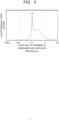
- FIG. 3 illustrates one example of a pore size distribution determined by a mercury intrusion method.
- the porous membrane applied to the separator 50 preferably gives a pore size distribution defined by a graph having a horizontal axis and a vertical axis, the horizontal axis representing pore sizes of pores of the porous membrane, the pore size being determined by the mercury intrusion method, the vertical axis representing differential pore volumes corresponding to the determined pore sizes (differential pore volumes of the pores), the pore size distribution having a peak top in a range of not less than 0.05 ⁇ m nor more than 1 ⁇ m. Pore sizes of clogged holes (non-through holes) in a surface of the porous membrane is determined by the mercury intrusion method.
- a peak top of more than 1 ⁇ m in the pore size distribution determined by such a mercury intrusion method prevents effective formation of the wet seal, and causes the crossover of the gases and the liquid between the anode 41 and the cathode 31, which makes performance likely to decrease.
- the peak top in the pore size distribution of the porous membrane determined by the porometer is more preferably not less than 0.01 ⁇ m nor more than 0.2 ⁇ m.
- the peak top in the pore size distribution of the porous membrane determined by the mercury intrusion method is more preferably not less than 0.05 ⁇ m nor more than 0.8 ⁇ m.
- the pore size distribution of the porous membrane determined by the porometer can be determined using, for example, POROLUX 1000 manufactured by Porometer N.V. or a measuring device equivalent to POROLUX 1000.
- the pore size distribution of the porous membrane by using the mercury intrusion method is determined using, for example, AutoPore V9610 manufactured by Micromeritics Instrument Corporation or a measuring device equivalent to V9610.
- the ISO air permeance of the porous membrane is determined using, for example, G-B3C manufactured by Toyo Seiki Seisaku-sho Ltd. or a measuring device equivalent to G-B3C.
- the porous membrane having the through hole When the porous membrane having the through hole is applied to the separator 50, for the use of the metal material containing titanium for the porous substrate of the anode 41, the titanium oxide having hydrophilicity precipitates in the interior and on a surface of the through hole at the time of operation of the cell 20, which allows an increase in formability of the wet seal through the hydrophilicity of the titanium oxide.
- the peak top in the range of not less than 0.01 ⁇ m nor more than 0.3 ⁇ m in the pore size distribution of the porous membrane determined by the porometer and the ISO air permeance of the porous membrane of not less than 0.8 ⁇ m/Pa•s nor more than 150 ⁇ m/Pa•s allow titanium oxide to suitably precipitate in the interior and on the surface of the through hole.
- porous membrane in which the peak top in the pore size distribution of the through holes determined by the porometer and the ISO air permeance have suitable values allows the titanium oxide with a suitable amount to be precipitated in the through holes of the porous membrane. Consequently, the formability and safety of the wet seal can be sufficiently enhanced.
- the amount of the titanium oxide to be formed in the through holes of the porous membrane is preferably controlled so that titanium is contained in at least one pore of the porous membrane when the cell 20 is operated at a current density of 200 mA/cm 2 or more for 1000 hours or longer, for example.
- an amount of the titanium in pores of the porous membrane may be defined by a mass ratio of a mass of any titanium compounds including titanium oxide to a mass of carbon in the porous membrane composed of the organic polymer material, and the mass ratio of the mass of any titanium compounds in the at least one pores is preferably 0.0001 or more when the mass of carbon in the porous membrane is relatively assumed to 1.
- the mass ratio is preferably 1 or less.
- a mass of any titanium compounds contained in the anode porous part is preferably larger than a mass of any titanium compounds contained in the cathode porous part. This allows the pores in the porous membrane to be effectively filled with the electrolytic solution having a sufficient concentration and flowing to the anode 41, resulting in continuing stable characteristics.
- Such a porous membrane composed of the organic polymer material and used for the separator 50 as described above can be manufactured as follows, for example.
- Example methods of manufacturing of an organic polymer porous membrane include various methods such as a phase separation method, a melt quenching method, an extraction method, a chemical treatment method, a stretching method, an irradiation etching method, a melting method, a foaming method, a compounding method, and fiber hollowing, and the example methods are not particularly limited.
- nonsolvent-induced phase separation in which bringing a homogeneous membrane-forming raw material solution obtained by dissolving an organic polymer in a solvent into contact with a coagulating solution containing a nonsolvent causes a concentration gradient between the solvent in the membrane-forming raw material solution and the nonsolvent in a coagulation bath, and the nonsolvent substitutes for the solvent in the membrane-forming raw material solution by using the concentration gradient as driving force to thereby promote a phase separation phenomenon, or a method of manufacturing using a thermally induced phase separation phenomenon in which cooling a polymer solution dissolved at high temperatures induces phase separation to increase pores, or there can be selected a method in which for such a material likely to become fibers as the fluorocarbon resin, fine pores are provided in the membrane by applying shear force, or the like.
- NIPS nonsolvent-induced phase separation
- combining these methods allows a predetermined porous structure to be obtained, and an inorganic substance may be compounded with the membrane, or coating for controlling the hydrophilicity may be performed on a surface. Further, a plurality of the membranes may be superposed.
- the carbon dioxide gas supplied to the cathode flow path 32 may be supplied in a dry state, but is more preferably humidified.
- the porous membrane of the organic polymer material is applied to the separator 50, using the carbon dioxide gas in the humidified state facilitates the formation of the wet seal in the porous membrane of the organic polymer material.
- the wet seal prevents the crossover between the anode part 40 and the cathode part 30 as described above.
- the gas supply 60 may include the humidifying unit which humidifies the carbon dioxide gas flowing through the gas pipe 63.
- the humidifying unit includes, for example, a humidification water tank, and is configured to humidify the carbon dioxide gas by vaporizing humidification water using an ultrasonic oscillator or the like. Further, the carbon dioxide gas may be humidified by being bubbled in the humidification water tank and passed therethrough.
- the carbon compound as the reduction product of carbon dioxide is not limited to carbon monoxide, and may be methane (CH 4 ), ethane (C 2 H 6 ), ethylene (C 2 H 4 ), methanol (CH 3 OH), ethanol (C 2 H 5 OH), ethylene glycol (C 2 H 6 O 2 ), or the like, and moreover, carbon monoxide which is the reduction product may be further reduced to produce the organic compounds.
- H + produced in the anode moves in the electrolytic solution existing in the anode 41 and the separator 50, and reaches the vicinity of the cathode 31.
- the reduction reaction of carbon dioxide (CO 2 ) occurs by using electrons (e - ) based on the current supplied from the power supply 80 to the cathode 31 and H + moved to the vicinity of the cathode 31.
- CO 2 supplied from the cathode flow path 32 to the cathode 31 is reduced to produce CO.
- hydrogen ions (H + ) receive electrons, thereby producing hydrogen. At this time, hydrogen may be produced simultaneously with the production of carbon monoxide.
- hydroxide ions (OH - ) produced by these reactions diffuse in the vicinity of the anode 41, and as presented in the following formula (6), the hydroxide ions (OH - ) are oxidized to produce oxygen (O 2 ).
- O 2 oxygen
- the carbon dioxide electrolysis device 10 of the arrangement as described above is not only specialized in only the reduction of carbon dioxide, but also, for example, can produce carbon monoxide and hydrogen at 1:2, and produce a carbon dioxide reduction product and hydrogen at an optional ratio at which methanol is produced in a chemical reaction thereafter, or the like.
- Hydrogen is a material which is inexpensive and easy to obtain through the electrolysis of water and from fossil fuel, and thus a ratio of hydrogen is not required to be large.
- a ratio of carbon monoxide to hydrogen is at least 1 or more, and desirably 1.5 or more from these viewpoints, which is preferable from economical and environmental viewpoints.
- the device 10 of the arrangement controls the pore size of the through hole and the ISO air permeance of the porous membrane used as the separator 50 to suitable values allows improvement in the wet sealing property of the separator 50 in operating the cell 20.
- This allows, in operating of the cell 20, the inhibition of the movement of the gases and the liquid between the anode part 40 and the cathode part 30 and the reaction between the gases due to the movement, that is, the occurrence of the crossover. Consequently, the device 10 can be stably operated over a long period of time.
- a composing material of a cathode catalyst layer catalytic particles in which Au nanoparticles (metal catalyst) each having an average diameter of 2 nm were supported on carbon particles, and a Nafion solution (trade name, manufactured by Du Pont de Nemours, Inc.) as an ion-conductive material (ion-exchange resin) were prepared.
- the composing material, pure water, and isopropanol were mixed at predetermined ratios to prepare catalyst coating solutions.
- Sheets of carbon paper with a diffusion layer having a microporous layer were each prepared as an electrode base material.
- a spray nozzle was filled with the catalyst coating solutions, which were sprayed on the sheets of carbon paper disposed on a heated hot plate, and spray coating was performed to be in such conditions as presented in Table 1.
- a mass of the metal catalyst per unit area of the catalyst layer was set to 0.15 mg/cm 2 . These were cut into a size of 4 cm ⁇ 4 cm to serve as cathodes (each electrode area: 16 cm 2 ). The detailed conditions are as presented in Table 1.
- an electrode in which a titanium nonwoven fabric was coated thereon with IrO 2 nanoparticles serving as a catalyst was used as a base, and elements presented in Table 1 were each added thereto.
- the element addition to the titanium nonwoven fabrics formed thin films of the elements on the titanium nonwoven fabrics, and the thin films were alloyed by heat treatment.
- the IrO 2 /(the alloy layers of the additive elements and titanium/formation as necessary)/titanium nonwoven fabrics were cut into 4 ⁇ 4 cm to serve as the anodes (each electrode area: 16 cm 2 ).
- separators membranes presented in Table 1 were used.
- Table 1 regarding peak tops in pore size distributions of through holes determined by using a porometer and peak tops in pore size distributions determined by mercury intrusion, values were read from graphs as FIG. 2 and FIG. 3 illustrated a case of the separator of Example 1.
- the separators in Examples 1 to 13 were porous membranes using organic polymer materials presented in Table 1, and the pore size distributions were prepared by controlling the conditions at the time of previously-described production.
- the measurements of the pore size distributions of the separators using the mercury intrusion method and the porometer are performed in consideration of only a peak top in a range of 10 ⁇ m or less, and in no consideration of a peak in a range of more than 10 ⁇ m. This is because the peak in the range of more than 10 ⁇ m can be, for example, a peak caused by detecting a space between the membrane and the membrane as a pore.
- an electrolysis cell was fabricated.
- a cathode current collector, a cathode gas flow path, the cathode, the separator, the anode, an anode solution flow path, and an anode current collector were stacked in that order from the top, and sandwiched by support plates, and further fastened by bolts to fabricate the cell.
- the anode current collector and the cathode current collector were connected to an external power supply, an electrolytic solution was made to flow through the anode solution flow path, and a carbon dioxide gas was made to flow through the cathode gas flow path, resulting in fabricating a carbon dioxide electrolysis device.
- the electrolysis devices in Examples 1 to 13 and Comparative examples 1 to 3 were each operated under the conditions indicated below.
- the humidified carbon dioxide gas was supplied to the cathode gas flow path in a predetermined amount, and the electrolytic solution (an aqueous sodium hydrogen carbonate solution with a concentration of 0.1 M) was supplied to the anode solution flow path.
- a constant current of 200 mA/cm 2 was continuously applied between the anode and the cathode to perform an operation for 1000 hours.
- the separators after the operation for 1000 hours were taken out, and containing elements were analyzed using an ICP analysis and an infrared absorption method through high-frequency induction heating furnace combustion of the dissolved solutions.
- Table 2 presents analysis results, and retention rates of Faraday efficiency of CO after the operation for 1000 hours.
- Example 1 0.0003 99.8
- Example 2 0.0002 99.9
- Example 3 0.00015 99.6
- Example 4 0.0002 97.6
- Example 5 0.001 99.5
- Example 6 0.01 98.6
- Example 7 0.00018 95.1
- Example 8 0.00014 93
- Example 9 0.0001 90.1
- Example 10 0.0002 99.9
- Example 11 0.00015 99.7
- Example 12 0.00022 99.8
- An electrolysis cell comprising:
- the porous membrane gives a second pore size distribution defined by a second graph having a second horizontal axis and a second vertical axis, the second horizontal axis representing second pore sizes of the porous membrane, the second pore sizes being determined by a mercury intrusion method, the second vertical axis representing log differential pore volumes corresponding to the second pore sizes, and the second pore size distribution having a second peak top in a range of not less than 0.05 ⁇ m nor more than 1 ⁇ m.
- an amount of the titanium in the at least one pore is defined by a mass ratio of a mass of any titanium compounds in the at least one pore to a mass of carbon in the organic polymer porous membrane, and the mass ratio is 0.0001 or more when the mass of carbon in the organic polymer porous membrane is assumed to 1.
- porous membrane includes a fluorocarbon resin, polyether, polysulfone, polyethylene, polypropylene, or cellulose.
- an amount of the titanium in the at least one pores is defined by a mass ratio of a mass of any titanium compounds in the at least one pore to a mass of carbon in the organic polymer porous membrane, the mass ratio being 0.0001 nor more than 0.001 when the mass of carbon in the organic polymer porous membrane is assumed to 1.
- An electrolysis device comprising:
Landscapes
- Chemical & Material Sciences (AREA)
- Organic Chemistry (AREA)
- Engineering & Computer Science (AREA)
- Chemical Kinetics & Catalysis (AREA)
- Electrochemistry (AREA)
- Materials Engineering (AREA)
- Metallurgy (AREA)
- Inorganic Chemistry (AREA)
- Analytical Chemistry (AREA)
- Automation & Control Theory (AREA)
- Electrodes For Compound Or Non-Metal Manufacture (AREA)
- Electrolytic Production Of Non-Metals, Compounds, Apparatuses Therefor (AREA)
Applications Claiming Priority (2)
| Application Number | Priority Date | Filing Date | Title |
|---|---|---|---|
| JP2023072196 | 2023-04-26 | ||
| JP2024016578A JP2024159486A (ja) | 2023-04-26 | 2024-02-06 | 電解セル及び電解装置 |
Publications (2)
| Publication Number | Publication Date |
|---|---|
| EP4455371A2 true EP4455371A2 (de) | 2024-10-30 |
| EP4455371A3 EP4455371A3 (de) | 2025-05-07 |
Family
ID=90365099
Family Applications (1)
| Application Number | Title | Priority Date | Filing Date |
|---|---|---|---|
| EP24163202.5A Pending EP4455371A3 (de) | 2023-04-26 | 2024-03-13 | Elektrolysezelle und elektrolysevorrichtung |
Country Status (3)
| Country | Link |
|---|---|
| US (1) | US20240360565A1 (de) |
| EP (1) | EP4455371A3 (de) |
| AU (2) | AU2024201522A1 (de) |
Family Cites Families (5)
| Publication number | Priority date | Publication date | Assignee | Title |
|---|---|---|---|---|
| JP2019056136A (ja) * | 2017-09-20 | 2019-04-11 | 株式会社東芝 | 電気化学反応装置 |
| WO2020132064A1 (en) * | 2018-12-18 | 2020-06-25 | Opus 12 Inc. | Electrolyzer and method of use |
| JP7413304B2 (ja) * | 2021-03-18 | 2024-01-15 | 株式会社東芝 | 二酸化炭素電解装置 |
| JP7524118B2 (ja) * | 2021-03-18 | 2024-07-29 | 株式会社東芝 | 二酸化炭素電解装置 |
| WO2023038116A1 (ja) * | 2021-09-10 | 2023-03-16 | 旭化成株式会社 | 二酸化炭素還元電解槽、二酸化炭素還元装置、当該二酸化炭素還元装置を用いる電解方法、並びに一酸化炭素又はエチレンの製造方法 |
-
2024
- 2024-03-07 AU AU2024201522A patent/AU2024201522A1/en not_active Abandoned
- 2024-03-12 US US18/602,075 patent/US20240360565A1/en active Pending
- 2024-03-13 EP EP24163202.5A patent/EP4455371A3/de active Pending
-
2026
- 2026-04-27 AU AU2026203126A patent/AU2026203126A1/en active Pending
Also Published As
| Publication number | Publication date |
|---|---|
| AU2026203126A1 (en) | 2026-05-14 |
| US20240360565A1 (en) | 2024-10-31 |
| EP4455371A3 (de) | 2025-05-07 |
| AU2024201522A1 (en) | 2024-11-14 |
Similar Documents
| Publication | Publication Date | Title |
|---|---|---|
| US10961632B2 (en) | Carbon dioxide electrolytic device and method of electrolyzing carbon dioxide | |
| US12529155B2 (en) | Carbon dioxide electrolysis device | |
| US10865490B2 (en) | Carbon dioxide electrolytic device | |
| AU2013273919B2 (en) | Gas permeable electrode and method of manufacture | |
| KR20210131999A (ko) | 전해기 및 사용 방법 | |
| US12241170B2 (en) | Carbon dioxide electrolytic device | |
| CA3238869A1 (en) | Reactor with advanced architecture for the electrochemical reaction of co2, co, and other chemical compounds | |
| US11098409B2 (en) | Electrolytic cell and electrolytic device for carbon dioxide | |
| JP7524118B2 (ja) | 二酸化炭素電解装置 | |
| US12031219B2 (en) | Carbon dioxide electrolytic device and method of electrolyzing carbon dioxide | |
| AU2023201037B2 (en) | Electrolytic device | |
| JP7858603B2 (ja) | 二酸化炭素電解装置及び二酸化炭素電解方法 | |
| US20240360565A1 (en) | Electrolysis cell and electrolysis device | |
| US20260139391A1 (en) | Membrane electrode assembly, electrolysis cell, and electrolysis device | |
| US20260139392A1 (en) | Membrane electrode assembly, electrolysis cell, and electrolysis device | |
| CN118854321A (zh) | 电解槽及电解装置 | |
| JP2024159486A (ja) | 電解セル及び電解装置 | |
| US20240318324A1 (en) | Carbon dioxide electrolytic device and method of electrolyzing carbon dioxide | |
| AU2023226658B2 (en) | Electrode, membrane electrode assembly, electrochemical cell, stack, and electrolyzer | |
| US20230304171A1 (en) | Electrolytic device and method of driving electrolytic device | |
| CN122039096A (zh) | 膜电极接合体、电解槽和电解装置 | |
| CN122039095A (zh) | 膜电极接合体、电解槽和电解装置 | |
| WO2023182419A1 (ja) | 電気化学的還元装置 | |
| CN118685798A (zh) | 二氧化碳电解装置和二氧化碳电解方法 |
Legal Events
| Date | Code | Title | Description |
|---|---|---|---|
| PUAI | Public reference made under article 153(3) epc to a published international application that has entered the european phase |
Free format text: ORIGINAL CODE: 0009012 |
|
| STAA | Information on the status of an ep patent application or granted ep patent |
Free format text: STATUS: REQUEST FOR EXAMINATION WAS MADE |
|
| 17P | Request for examination filed |
Effective date: 20240313 |
|
| AK | Designated contracting states |
Kind code of ref document: A2 Designated state(s): AL AT BE BG CH CY CZ DE DK EE ES FI FR GB GR HR HU IE IS IT LI LT LU LV MC ME MK MT NL NO PL PT RO RS SE SI SK SM TR |
|
| PUAL | Search report despatched |
Free format text: ORIGINAL CODE: 0009013 |
|
| AK | Designated contracting states |
Kind code of ref document: A3 Designated state(s): AL AT BE BG CH CY CZ DE DK EE ES FI FR GB GR HR HU IE IS IT LI LT LU LV MC ME MK MT NL NO PL PT RO RS SE SI SK SM TR |
|
| RIC1 | Information provided on ipc code assigned before grant |
Ipc: C25B 11/091 20210101ALI20250402BHEP Ipc: C25B 11/065 20210101ALI20250402BHEP Ipc: C25B 11/063 20210101ALI20250402BHEP Ipc: C25B 11/032 20210101ALI20250402BHEP Ipc: C25B 11/031 20210101ALI20250402BHEP Ipc: C25B 9/23 20210101ALI20250402BHEP Ipc: C25B 3/26 20210101ALI20250402BHEP Ipc: C25B 3/03 20210101ALI20250402BHEP Ipc: C25B 1/23 20210101ALI20250402BHEP Ipc: C25B 1/04 20210101ALI20250402BHEP Ipc: C25B 13/05 20210101ALI20250402BHEP Ipc: C25B 13/08 20060101AFI20250402BHEP |