EP4455449A1 - Turbine - Google Patents
Turbine Download PDFInfo
- Publication number
- EP4455449A1 EP4455449A1 EP22927239.8A EP22927239A EP4455449A1 EP 4455449 A1 EP4455449 A1 EP 4455449A1 EP 22927239 A EP22927239 A EP 22927239A EP 4455449 A1 EP4455449 A1 EP 4455449A1
- Authority
- EP
- European Patent Office
- Prior art keywords
- shroud
- rotor blade
- turbine
- rotor
- circumferential direction
- Prior art date
- Legal status (The legal status is an assumption and is not a legal conclusion. Google has not performed a legal analysis and makes no representation as to the accuracy of the status listed.)
- Pending
Links
Images




Classifications
-
- F—MECHANICAL ENGINEERING; LIGHTING; HEATING; WEAPONS; BLASTING
- F01—MACHINES OR ENGINES IN GENERAL; ENGINE PLANTS IN GENERAL; STEAM ENGINES
- F01D—NON-POSITIVE DISPLACEMENT MACHINES OR ENGINES, e.g. STEAM TURBINES
- F01D5/00—Blades; Blade-carrying members; Heating, heat-insulating, cooling or antivibration means on the blades or the members
- F01D5/12—Blades
- F01D5/14—Form or construction
- F01D5/18—Hollow blades, i.e. blades with cooling or heating channels or cavities; Heating, heat-insulating or cooling means on blades
-
- F—MECHANICAL ENGINEERING; LIGHTING; HEATING; WEAPONS; BLASTING
- F01—MACHINES OR ENGINES IN GENERAL; ENGINE PLANTS IN GENERAL; STEAM ENGINES
- F01D—NON-POSITIVE DISPLACEMENT MACHINES OR ENGINES, e.g. STEAM TURBINES
- F01D5/00—Blades; Blade-carrying members; Heating, heat-insulating, cooling or antivibration means on the blades or the members
- F01D5/12—Blades
- F01D5/22—Blade-to-blade connections, e.g. for damping vibrations
- F01D5/225—Blade-to-blade connections, e.g. for damping vibrations by shrouding
-
- F—MECHANICAL ENGINEERING; LIGHTING; HEATING; WEAPONS; BLASTING
- F01—MACHINES OR ENGINES IN GENERAL; ENGINE PLANTS IN GENERAL; STEAM ENGINES
- F01D—NON-POSITIVE DISPLACEMENT MACHINES OR ENGINES, e.g. STEAM TURBINES
- F01D25/00—Component parts, details, or accessories, not provided for in, or of interest apart from, other groups
- F01D25/08—Cooling; Heating; Heat-insulation
- F01D25/12—Cooling
-
- F—MECHANICAL ENGINEERING; LIGHTING; HEATING; WEAPONS; BLASTING
- F01—MACHINES OR ENGINES IN GENERAL; ENGINE PLANTS IN GENERAL; STEAM ENGINES
- F01D—NON-POSITIVE DISPLACEMENT MACHINES OR ENGINES, e.g. STEAM TURBINES
- F01D5/00—Blades; Blade-carrying members; Heating, heat-insulating, cooling or antivibration means on the blades or the members
- F01D5/12—Blades
- F01D5/14—Form or construction
- F01D5/18—Hollow blades, i.e. blades with cooling or heating channels or cavities; Heating, heat-insulating or cooling means on blades
- F01D5/187—Convection cooling
-
- F—MECHANICAL ENGINEERING; LIGHTING; HEATING; WEAPONS; BLASTING
- F01—MACHINES OR ENGINES IN GENERAL; ENGINE PLANTS IN GENERAL; STEAM ENGINES
- F01D—NON-POSITIVE DISPLACEMENT MACHINES OR ENGINES, e.g. STEAM TURBINES
- F01D5/00—Blades; Blade-carrying members; Heating, heat-insulating, cooling or antivibration means on the blades or the members
- F01D5/02—Blade-carrying members, e.g. rotors
- F01D5/027—Arrangements for balancing
-
- F—MECHANICAL ENGINEERING; LIGHTING; HEATING; WEAPONS; BLASTING
- F01—MACHINES OR ENGINES IN GENERAL; ENGINE PLANTS IN GENERAL; STEAM ENGINES
- F01D—NON-POSITIVE DISPLACEMENT MACHINES OR ENGINES, e.g. STEAM TURBINES
- F01D5/00—Blades; Blade-carrying members; Heating, heat-insulating, cooling or antivibration means on the blades or the members
- F01D5/12—Blades
- F01D5/14—Form or construction
- F01D5/16—Form or construction for counteracting blade vibration
-
- F—MECHANICAL ENGINEERING; LIGHTING; HEATING; WEAPONS; BLASTING
- F05—INDEXING SCHEMES RELATING TO ENGINES OR PUMPS IN VARIOUS SUBCLASSES OF CLASSES F01-F04
- F05D—INDEXING SCHEME FOR ASPECTS RELATING TO NON-POSITIVE-DISPLACEMENT MACHINES OR ENGINES, GAS-TURBINES OR JET-PROPULSION PLANTS
- F05D2240/00—Components
- F05D2240/20—Rotors
- F05D2240/24—Rotors for turbines
-
- F—MECHANICAL ENGINEERING; LIGHTING; HEATING; WEAPONS; BLASTING
- F05—INDEXING SCHEMES RELATING TO ENGINES OR PUMPS IN VARIOUS SUBCLASSES OF CLASSES F01-F04
- F05D—INDEXING SCHEME FOR ASPECTS RELATING TO NON-POSITIVE-DISPLACEMENT MACHINES OR ENGINES, GAS-TURBINES OR JET-PROPULSION PLANTS
- F05D2250/00—Geometry
- F05D2250/10—Two-dimensional
- F05D2250/13—Two-dimensional trapezoidal
-
- F—MECHANICAL ENGINEERING; LIGHTING; HEATING; WEAPONS; BLASTING
- F05—INDEXING SCHEMES RELATING TO ENGINES OR PUMPS IN VARIOUS SUBCLASSES OF CLASSES F01-F04
- F05D—INDEXING SCHEME FOR ASPECTS RELATING TO NON-POSITIVE-DISPLACEMENT MACHINES OR ENGINES, GAS-TURBINES OR JET-PROPULSION PLANTS
- F05D2250/00—Geometry
- F05D2250/20—Three-dimensional
- F05D2250/23—Three-dimensional prismatic
-
- F—MECHANICAL ENGINEERING; LIGHTING; HEATING; WEAPONS; BLASTING
- F05—INDEXING SCHEMES RELATING TO ENGINES OR PUMPS IN VARIOUS SUBCLASSES OF CLASSES F01-F04
- F05D—INDEXING SCHEME FOR ASPECTS RELATING TO NON-POSITIVE-DISPLACEMENT MACHINES OR ENGINES, GAS-TURBINES OR JET-PROPULSION PLANTS
- F05D2250/00—Geometry
- F05D2250/30—Arrangement of components
- F05D2250/31—Arrangement of components according to the direction of their main axis or their axis of rotation
- F05D2250/314—Arrangement of components according to the direction of their main axis or their axis of rotation the axes being inclined in relation to each other
-
- F—MECHANICAL ENGINEERING; LIGHTING; HEATING; WEAPONS; BLASTING
- F05—INDEXING SCHEMES RELATING TO ENGINES OR PUMPS IN VARIOUS SUBCLASSES OF CLASSES F01-F04
- F05D—INDEXING SCHEME FOR ASPECTS RELATING TO NON-POSITIVE-DISPLACEMENT MACHINES OR ENGINES, GAS-TURBINES OR JET-PROPULSION PLANTS
- F05D2250/00—Geometry
- F05D2250/70—Shape
- F05D2250/73—Shape asymmetric
-
- F—MECHANICAL ENGINEERING; LIGHTING; HEATING; WEAPONS; BLASTING
- F05—INDEXING SCHEMES RELATING TO ENGINES OR PUMPS IN VARIOUS SUBCLASSES OF CLASSES F01-F04
- F05D—INDEXING SCHEME FOR ASPECTS RELATING TO NON-POSITIVE-DISPLACEMENT MACHINES OR ENGINES, GAS-TURBINES OR JET-PROPULSION PLANTS
- F05D2260/00—Function
- F05D2260/20—Heat transfer, e.g. cooling
-
- F—MECHANICAL ENGINEERING; LIGHTING; HEATING; WEAPONS; BLASTING
- F05—INDEXING SCHEMES RELATING TO ENGINES OR PUMPS IN VARIOUS SUBCLASSES OF CLASSES F01-F04
- F05D—INDEXING SCHEME FOR ASPECTS RELATING TO NON-POSITIVE-DISPLACEMENT MACHINES OR ENGINES, GAS-TURBINES OR JET-PROPULSION PLANTS
- F05D2260/00—Function
- F05D2260/96—Preventing, counteracting or reducing vibration or noise
- F05D2260/961—Preventing, counteracting or reducing vibration or noise by mistuning rotor blades or stator vanes with irregular interblade spacing, airfoil shape
Definitions
- the present disclosure relates to a turbine.
- PTL 1 discloses a configuration in which a shroud is provided in each of a plurality of blades, and the shrouds adjacent to each other are divided from each other and a pin engaging hole into which a pin is inserted to have a play is formed.
- a technique described in PTL 1 is to suppress the excitation of the blade by the pin being in sliding contact with the pin engaging hole, and a sliding contact portion of the pin is limited. Therefore, a damping effect of suppressing the vibration of the blade is small.
- the present disclosure has been made in view of the above-described problems, and an object thereof is to provide a turbine capable of obtaining a high damping effect with respect to vibration of a blade.
- a turbine includes a rotor; and a plurality of turbine blades disposed along a circumferential direction of the rotor, in which the plurality of turbine blades include a first turbine blade including a first rotor blade and a first shroud provided on a tip portion of the first rotor blade, and a second turbine blade including a second rotor blade disposed adjacent to the first rotor blade on one side in the circumferential direction of the rotor and a second shroud provided on a tip portion of the second rotor blade, in an overlap region in which at least a part of one side surface of the first shroud on the one side in the circumferential direction and at least a part of an other side surface of the second shroud on the other side in the circumferential direction overlap each other in the circumferential direction, the one side surface is located on an outer side in a radial direction with respect to the other side surface, and the second shroud is heavier than the first sh
- Fig. 1 is a diagram schematically showing a configuration example of a gas turbine 100 including a turbine 1 according to some embodiments.
- the gas turbine 100 includes a compressor 102 for generating compressed air G2, a combustor 104 for generating a combustion gas G3 by using the compressed air G2 and a fuel, and a turbine 1 configured to be rotationally driven by the combustion gas G3.
- the gas turbine 100 is applied, for example, as an aircraft engine for obtaining a propulsion force of an aircraft.
- the gas turbine 100 may be used for another purpose such as power generation.
- the compressor 102 includes a compressor rotor 106, a compressor casing 108, a plurality of compressor stator blade rows 110, and a plurality of compressor rotor blade rows 112.
- the compressor rotor 106 is configured to rotate around an axis O.
- the compressor rotor 106 has a rod shape and has a longitudinal direction along an axial direction D1 in which the axis O extends.
- the compressor casing 108 has a cylindrical shape and covers the compressor rotor 106 from outside in a radial direction of the compressor rotor 106.
- the plurality of compressor stator blade rows 110 are fixed to the compressor casing 108 at intervals from each other along the axial direction D1.
- Each of the plurality of compressor stator blade rows 110 includes a plurality of compressor stator blades 111 disposed at intervals from each other along a circumferential direction of the compressor rotor 106 on an inner peripheral surface of the compressor casing 108.
- the plurality of compressor rotor blade rows 112 are embedded in the compressor rotor 106 at intervals from each other along the axial direction D1 so as to be alternately arranged with respect to the compressor stator blade rows 110.
- Each of the plurality of compressor rotor blade rows 112 includes a plurality of compressor rotor blades 113 disposed at intervals from each other along the circumferential direction of the compressor rotor 106 on an outer peripheral surface of the compressor rotor 106.
- an air intake port 114 for taking in air G1 from the outside is formed.
- the air G1 taken into the compressor 102 is compressed by passing through the plurality of compressor stator blade rows 110 and the plurality of compressor rotor blade rows 112, and becomes high-temperature and highpressure compressed air G2.
- the combustor 104 is supplied with a fuel and the compressed air G2 generated by the compressor 102, and generates a combustion gas G3, which is a working fluid of the turbine 1, by mixing and combusting the fuel and the compressed air G2.
- the gas turbine 100 includes a combustor casing 116 disposed between the compressor casing 108 and a turbine casing 6 (described later) in the axial direction D1.
- a plurality of the combustors 104 are disposed in the combustor casing 116.
- the turbine 1 includes a turbine rotor 3, the turbine casing 6, a plurality of turbine stator blade rows 8, and a plurality of turbine rotor blade rows 10.
- the turbine rotor 3 is configured to be rotatable around the axis O.
- the turbine rotor 3 has a rod shape and has a longitudinal direction along the axial direction D1.
- the turbine rotor 3 and the compressor rotor 106 are integrally connected to each other in the axial direction D1.
- the gas turbine 100 includes a gas turbine rotor 101 that is configured to include the turbine rotor 3 and the compressor rotor 106.
- a radial direction of the turbine rotor 3 will be simply referred to as a "radial direction D2", and a circumferential direction of the turbine rotor 3 will be simply referred to as a “circumferential direction D3".
- the radial direction D2 is orthogonal to the axis O.
- a direction approaching the axis O is defined as a direction toward an inner side in the radial direction D2
- a direction away from the axis O is defined as a direction toward an outer side in the radial direction D2.
- the turbine casing 6 has a cylindrical shape and covers the turbine rotor 3 from outside in the radial direction D2.
- the plurality of turbine stator blade rows 8 are fixed to the turbine casing 6 at intervals from each other along the axial direction D1.
- Each of the plurality of turbine stator blade rows 8 includes a plurality of turbine stator blades 12 disposed at intervals from each other along the circumferential direction D3 on an inner peripheral surface of the turbine casing 6.
- the plurality of turbine rotor blade rows 10 are embedded in the turbine rotor 3 at intervals from each other along the axial direction D1 so as to be alternately arranged with respect to the turbine stator blade rows 8.
- Each of the plurality of turbine rotor blade rows 10 includes a plurality of turbine rotor blades 2 disposed along the circumferential direction D3 on an outer peripheral surface of the turbine rotor 3.
- the turbine 1 illustrated in Fig. 1 is supplied with the combustion gas G3 generated by the combustor 104, and the turbine rotor 3 is rotationally driven by the combustion gas G3 passing through the plurality of turbine stator blade rows 8 and the plurality of turbine rotor blade rows 10.
- the compressor 102 compresses the air G1 flowing inside the compressor 102 by transmitting a rotational force of the turbine 1 through the turbine rotor 3.
- the turbine 1 exhausts the combustion gas G3 (exhaust gas G4) that has passed through the plurality of turbine stator blade rows 8 and the plurality of turbine rotor blade rows 10 as a propulsion force of an aircraft.
- the gas turbine 100 further includes a fan disposed on a side opposite to the turbine 1 with the compressor 102 interposed therebetween in the axial direction D1 in order to increase an amount of the air G1 taken into the compressor 102.
- the fan is connected to the turbine rotor 3 via the compressor rotor 106 and is rotationally driven by a rotational force of the turbine 1.
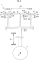
- Fig. 2 is a diagram schematically showing a configuration of the turbine 1 according to the first embodiment.
- Fig. 2 is a schematic view of a part of the turbine rotor blade row 10 of Fig. 1 as viewed in the axial direction D1.
- the turbine 1 includes a rotor disc 14 fixed to the turbine rotor 3.
- the rotor disc 14 is fixed to the turbine rotor 3, for example, by being fitted into a hole formed in the outer peripheral surface of the turbine rotor 3.
- the rotor disc 14 is fixed to the turbine rotor 3 by a fastener such as a bolt.
- the rotor disc 14 includes a radially extending portion 16 connected to the turbine rotor 3 and extending from the turbine rotor 3 to the outer side in the radial direction D2, and a circumferentially extending portion 18 extending from a tip portion of the radially extending portion 16 to both sides in the circumferential direction D3 and having a plate shape.
- the plurality of turbine rotor blades 2 include a first turbine rotor blade 2A (2), a second turbine rotor blade 2B (2), and a third turbine rotor blade 2C (2).
- the first turbine rotor blade 2A includes a first rotor blade 20 and a first shroud 24 provided on a tip portion 22 of the first rotor blade 20.
- the first rotor blade 20 is attached to an outer peripheral surface of the circumferentially extending portion 18 and extends to the outer side in the radial direction D2 from the outer peripheral surface of the circumferentially extending portion 18.
- the first shroud 24 has a plate shape and extends from the tip portion 22 of the first rotor blade 20 to both sides in the circumferential direction D3.
- one side surface 24a of the first shroud 24 on one side in the circumferential direction D3 has an outer end e1 on an outer side in the radial direction D2 located on the one side in the circumferential direction D3 with respect to an inner end e2 on an inner side in the radial direction D2.
- the other side surface 24b of the first shroud 24 on the other side in the circumferential direction D3 has an outer end e3 on the outer side in the radial direction D2 located on the other side in the circumferential direction D3 with respect to an inner end e4 on the inner side in the radial direction D2.
- Each of the one side surface 24a and the other side surface 24b of the first shroud 24 faces the rotor disc 14 side (inner side) in the radial direction D2.
- the first shroud 24 has a symmetrical shape when viewed in the axial direction D1.
- the tip portion 22 of the first rotor blade 20 is located on a central portion of the first shroud 24 in the circumferential direction D3.
- the second turbine rotor blade 2B includes a second rotor blade 40 and a second shroud 44 provided on a tip portion 42 of the second rotor blade 40.
- the second rotor blade 40 is disposed adjacent to the first rotor blade 20 on one side in the circumferential direction D3.
- a space through which the combustion gas G3 flows is formed between the first rotor blade 20 and the second rotor blade 40.
- the second rotor blade 40 is attached to the outer peripheral surface of the circumferentially extending portion 18 and extends to the outer side in the radial direction D2 from the outer peripheral surface of the circumferentially extending portion 18.
- the second shroud 44 has a plate shape and extends from the tip portion 42 of the second rotor blade 40 to both sides in the circumferential direction D3.
- one side surface 44a of the second shroud 44 on one side in the circumferential direction D3 has an outer end e5 on an outer side in the radial direction D2 located on the other side in the circumferential direction D3 with respect to an inner end e6 on an inner side in the radial direction D2.
- the other side surface 44b of the second shroud 44 on the other side in the circumferential direction D3 has an outer end e7 on the outer side in the radial direction D2 located on the one side in the circumferential direction D3 with respect to an inner end e8 on the inner side in the radial direction D2.
- Each of one side surface 44a and the other side surface 44b of the second shroud 44 faces a side (outer side) opposite to the rotor disc 14 side in the radial direction D2.
- the second shroud 44 has a symmetrical shape when viewed in the axial direction D1.
- the tip portion 42 of the second rotor blade 40 is located on a central portion of the second shroud 44 in the circumferential direction D3.
- the third turbine rotor blade 2C includes a third rotor blade 60 and a third shroud 64 provided on a tip portion 62 of the third rotor blade 60.
- the third rotor blade 60 is disposed adjacent to the second rotor blade 40 on one side in the circumferential direction D3.
- a space through which the combustion gas G3 flows is formed between the second rotor blade 40 and the third rotor blade 60.
- the third rotor blade 60 is attached to the outer peripheral surface of the circumferentially extending portion 18 and extends to the outer side in the radial direction D2 from the outer peripheral surface of the circumferentially extending portion 18.
- the third shroud 64 has a plate shape and extends from the tip portion 62 of the third rotor blade 60 to both sides in the circumferential direction D3.
- one side surface 64a of the third shroud 64 on one side in the circumferential direction D3 has an outer end e9 on an outer side in the radial direction D2 located on the one side in the circumferential direction D3 with respect to an inner end e10 on an inner side in the radial direction D2.
- the other side surface 64b of the third shroud 64 on the other side in the circumferential direction D3 has an outer end e11 on the outer side in the radial direction D2 located on the other side in the circumferential direction D3 with respect to an inner end e12 on the inner side in the radial direction D2.
- Each of the one side surface 64a and the other side surface 64b of the third shroud 64 faces the rotor disc 14 side (inner side) in the radial direction D2.
- the third shroud 64 has a symmetrical shape when viewed in the axial direction D1.
- the tip portion 62 of the third rotor blade 60 is located in a central portion of the third shroud 64 in the circumferential direction D3.
- the first rotor blade 20, the second rotor blade 40, and the third rotor blade 60 are configured to have the same shape as each other. Further, the first rotor blade 20, the second rotor blade 40, and the third rotor blade 60 are made of the same material.
- FIG. 3 is a diagram for describing an example of a method for forming the turbine 1 according to the first embodiment.
- the turbine 1 employs a blisk structure in which the first turbine rotor blade 2A, the second turbine rotor blade 2B, the third turbine rotor blade 2C, and the rotor disc 14 are integrally configured by, for example, casting.
- the first shroud 24, the second shroud 44, and the third shroud 64 are integrally configured as a single component (integrated shroud 70) as a whole.
- Each of the one side surface 24a of the first shroud 24 and the other side surface 44b of the second shroud 44 is formed by a first cut surface 72 obtained by cutting the integrated shroud 70 along a first cutting line C1.
- a gap may be formed between the one side surface 24a of the first shroud 24 and the other side surface 44b of the second shroud 44, or the one side surface 24a of the first shroud 24 and the other side surface 44b of the second shroud 44 may be in contact with each other.
- the first cutting line C1 extends linearly and passes between a portion of the integrated shroud 70 (the central portion of the first shroud 24) to which the tip portion 22 of the first rotor blade 20 is connected and a portion of the integrated shroud 70 (the central portion of the second shroud 44) to which the tip portion 42 of the second rotor blade 40 is connected.
- the first cutting line C1 is closer to the central portion of the first shroud 24 than to the central portion of the second shroud 44 in the circumferential direction D3. That is, a length of the first shroud 24 in the circumferential direction D3 is shorter than a length of the second shroud 44 in the circumferential direction D3. Therefore, the second shroud 44 has a larger volume than the first shroud 24 and is heavier than the first shroud 24.
- Each of the one side surface 44a of the second shroud 44 and the other side surface 64b of the third shroud 64 is formed by a second cut surface 74 obtained by cutting the integrated shroud 70 along a second cutting line C2.
- a gap may be formed between the one side surface 44a of the second shroud 44 and the other side surface 64b of the third shroud 64, or the one side surface 44a of the second shroud 44 and the other side surface 64b of the third shroud 64 may be in contact with each other.
- the second cutting line C2 extends linearly and passes between a portion of the integrated shroud 70 (the central portion of the second shroud 44) to which the tip portion 42 of the second rotor blade 40 is connected and a portion of the integrated shroud 70 (the central portion of the third shroud 64) to which the tip portion 62 of the third rotor blade 60 is connected.
- the second cutting line C2 is closer to the central portion of the third shroud 64 than to the central portion of the second shroud 44 in the circumferential direction D3. That is, a length of the third shroud 64 in the circumferential direction D3 is shorter than the length of the second shroud 44 in the circumferential direction D3. Therefore, the second shroud 44 has a larger volume than the third shroud 64 and is heavier than the third shroud 64.
- the other side surface 24b of the first shroud 24 and the one side surface 64a of the third shroud 64 may be formed by cutting the integrated shroud 70.
- the integrated shroud 70 extends to the other side in the circumferential direction D3 from a forming portion of the other side surface 24b of the first shroud 24, and extends to the one side in the circumferential direction D3 from the one side surface 64a of the third shroud 64.
- the other side surface 24b of the first shroud 24 and the other side surface 64b of the third shroud 64 may be formed simultaneously with creation (casting) of the integrated shroud 70.
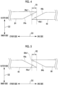
- Fig. 4 is an enlarged view of a periphery of the one side surface 24a of the first shroud 24 shown in Fig. 2 .
- Fig. 5 is an enlarged view of a periphery of the one side surface 44a of the second shroud 44 shown in Fig. 2 .
- each of the one side surface 24a of the first shroud 24 and the other side surface 44b of the second shroud 44 has a planar shape that is entirely a flat surface.
- a region in which a part 24a1 of the one side surface 24a of the first shroud 24 and a part 44b1 of the other side surface 44b of the second shroud 44 overlap each other in the circumferential direction D3 is defined as a first overlap region R1.
- the one side surface 24a of the first shroud 24 is located on the outer side in the radial direction D2 with respect to the other side surface 44b of the second shroud 44.
- each of the one side surface 44a of the second shroud 44 and the other side surface 64b of the third shroud 64 has a planar shape that is entirely a flat surface.
- a region where a part 44a1 of the one side surface 44a of the second shroud 44 and a part 64b1 of the other side surface 64b of the third shroud 64 overlap each other in the circumferential direction D3 is defined as a second overlap region R2.
- the one side surface 44a of the second shroud 44 is located on the outer side in the radial direction D2 with respect to the other side surface 64b of the third shroud 64.
- the second shroud 44 is heavier than the first shroud 24. Therefore, during the operation of the turbine 1, a centrifugal force acting on the second rotor blade 40 is larger than a centrifugal force acting on the first rotor blade 20. For this reason, the second rotor blade 40 extends longer along the radial direction D2 than the first rotor blade 20.
- the part 44b1 of the other side surface of the second shroud 44 is in a state of being in contact with or being pressed against the part 24a1 of the one side surface 24a of the first shroud 24. Therefore, when one or both of the first turbine rotor blade 2A and the second turbine rotor blade 2B vibrate, the part 44b1 of the other side surface 44b of the second shroud 44 can be slid on the part 24a1 of the one side surface 24a of the first shroud 24, and thus a high damping effect due to friction can be obtained.
- the first shroud 24 and the second shroud 44 have different shapes from each other. Therefore, a static deformation property of the first turbine rotor blade 2A and a static deformation property of the second turbine rotor blade 2B during the operation of the turbine 1 are different from each other. For this reason, natural frequencies of the first turbine rotor blade 2A and the second turbine rotor blade 2B become nonuniform with each other, and a so-called mistuning structure can be adopted for the turbine 1, so that the vibration of the turbine 1 can be suppressed.
- the second shroud 44 is heavier than the third shroud 64. Therefore, during the operation of the turbine 1, the centrifugal force acting on the second rotor blade 40 is larger than a centrifugal force acting on the third rotor blade 60. For this reason, the second rotor blade 40 extends longer along the radial direction D2 than the third rotor blade 60.
- the part 44a1 of the one side surface 44a of the second shroud 44 can be slid on the part 64b1 of the other side surface 64b of the third shroud 64, and thus a high damping effect due to friction can be obtained.
- the integrated shroud 70 by simply cutting the integrated shroud 70 along the first cutting line C1, it is possible to simultaneously form the one side surface 24a of the first shroud 24 and the other side surface 44b of the second shroud 44.
- the integrated shroud 70 along the second cutting line C2 it is possible to simultaneously form the one side surface 44a of the second shroud 44 and the other side surface 64b of the third shroud 64.
- the effort required to process the turbine 1 can be reduced.
- a sliding area can be increased as compared to PTL 1 in which the pin is slid on the pin engaging hole, a damping effect higher than that of PTL 1 can be obtained.
- the turbine 1 may include two turbine rotor blades 2 or four or more turbine rotor blades 2.
- first turbine rotor blade 2A, the second turbine rotor blade 2B, and the third turbine rotor blade 2C are mounted on the common rotor disc 14
- present disclosure is not limited to this form.
- the rotor disc 14 to which the first turbine rotor blade 2A is mounted and the rotor disc 14 to which the second turbine rotor blade 2B is mounted may be separate members.
- the rotor disc 14 to which the second turbine rotor blade 2B is mounted and the rotor disc 14 to which the third turbine rotor blade 2C is mounted may be separate members.
- the turbine 1 employs a blisk structure in which the turbine rotor blade 2 and the rotor disc 14 are integrally configured has been described as an example.
- the present disclosure is not limited to this form.
- the turbine rotor blade 2 and the rotor disc 14 may be separately configured.
- each of the first shroud 24, the second shroud 44, and the third shroud has a symmetrical shape when viewed in the axial direction D1.
- the present disclosure is not limited to this form. Any one of the first shroud 24, the second shroud 44, and the third shroud may have an asymmetric shape when viewed in the axial direction D1.
- the part 24a1 of the one side surface 24a of the first shroud and the part 44b1 of the other side surface 44b of the second shroud overlap each other in the first overlap region R1.
- the present disclosure is not limited to this form.
- the entirety of the one side surface 24a of the first shroud and the entirety of the other side surface 44b of the second shroud overlap each other in the first overlap region R1.
- the part 24a1 of the one side surface 24a of the first shroud and the entirety of the other side surface 44b of the second shroud overlap each other in the first overlap region R1.
- a turbine 1 according to a second embodiment of the present disclosure will be described.
- a shape of the one side surface 24a of the first shroud 24 is different from that of the turbine 1 according to the first embodiment.
- the same components as those in the first embodiment are designated by the same reference signs, and the detailed descriptions thereof will not be repeated.
- Fig. 6 is an enlarged view of the periphery of the one side surface 24a of the first shroud 24 according to the second embodiment.
- the one side surface 24a of the first shroud 24 includes an inward stepped surface 80 facing the inner side in the radial direction D2.
- the other side surface 44b of the second shroud 44 includes an outward stepped surface 82 facing the outer side in the radial direction D2.
- the one side surface 24a of the first shroud 24 includes the inward stepped surface 80, a first inner surface 81, and a first outer surface 83.
- the first inner surface 81 extends from the inner end e2 of the one side surface 24a of the first shroud 24 toward the outer side in the radial direction D2.
- the first outer surface 83 extends from the outer end e1 of the one side surface 24a of the first shroud 24 toward the inner side in the radial direction D2.
- the inward stepped surface 80 extends along the circumferential direction D3 and connects the first inner surface 81 and the first outer surface 83.
- the other side surface 44b of the second shroud 44 includes the outward stepped surface 82, a second inner surface 85, and a second outer surface 87.
- the second inner surface 85 extends from the inner end e8 of the other side surface 44b of the second shroud 44 toward the outer side in the radial direction D2.
- the second outer surface 87 extends from the outer end e7 of the other side surface 44b of the second shroud 44 toward the inner side in the radial direction D2.
- the outward stepped surface 82 extends along the circumferential direction D3 and connects the second inner surface 85 and the second outer surface 87.
- Each of the inward stepped surface 80 and the outward stepped surface 82 has a planar shape that is entirely a flat surface.
- the inward stepped surface 80 and the outward stepped surface 82 extend parallel to each other along the axial direction D1.
- the inward stepped surface 80 includes the part 24a1 of the one side surface 24a included in the first overlap region R1.
- the outward stepped surface 82 includes the part 44b1 of the other side surface 44b included in the first overlap region R1.
- the one side surface 24a of the first shroud 24 has a stepped shape
- the one side surface 44a of the second shroud 44 may have a stepped shape.
- a turbine 1 according to a third embodiment of the present disclosure will be described.
- the turbine 1 according to the third embodiment further limits a configuration of the turbine 1 according to the first embodiment.
- the same components as those in the first embodiment are designated by the same reference signs, and the detailed descriptions thereof will not be repeated.
- Fig. 7 is a diagram schematically showing an internal configuration of the first rotor blade 20 and an internal configuration of the second rotor blade 40 according to the third embodiment.
- a first cooling flow path 90 through which a first refrigerant F1 for cooling the first rotor blade 20 flows is formed inside the first rotor blade 20.
- An inlet and an outlet of the first cooling flow path 90 are formed in a blade root portion 23 of the first rotor blade 20 on a side opposite to the tip portion 22 of the first rotor blade 20 in the radial direction D2.
- a second cooling flow path 92 through which a second refrigerant F2 for cooling the second rotor blade 40 flows is formed inside the second rotor blade 40.
- An inlet and an outlet of the second cooling flow path 92 are formed in a blade root portion 43 of the second rotor blade 40 on a side opposite to the tip portion 42 of the second rotor blade 40 in the radial direction D2.
- the second refrigerant F2 is the same refrigerant as the first refrigerant F1.
- a first cooling surface 91 defining the first cooling flow path 90 has a larger area than a second cooling surface 93 defining the second cooling flow path 92.
- the first cooling flow path 90 is longer than the second cooling flow path 92.
- the first cooling flow path 90 has a larger flow path cross section than the second cooling flow path 92.
- the turbine 1 since the first cooling surface 91 has a larger area than the second cooling surface 93, thermal expansion acting on the second rotor blade 40 is larger than thermal expansion acting on the first rotor blade 20. That is, the second rotor blade 40 extends longer along the radial direction D2 than the first rotor blade 20 due to thermal expansion.
- the configurations of the first rotor blade 20 and the second rotor blade 40 according to the third embodiment described with reference to Fig. 7 may be applied to the turbine 1 according to the second embodiment.
- FIG. 8 is a diagram schematically showing a configuration of the turbine 1 according to the fourth embodiment.
- Fig. 8 shows two turbine rotor blades 2 included in the turbine rotor blade row 10 of Fig. 1 .
- the turbine 1 includes the rotor disc 14 fixed to the turbine rotor 3.
- the rotor disc 14 is fixed to the turbine rotor 3, for example, by being fitted into a hole formed in the outer peripheral surface of the turbine rotor 3.
- the rotor disc 14 is fixed to the turbine rotor 3 by a fastener such as a bolt.
- the plurality of turbine rotor blades 2 include a fourth turbine rotor blade 2D (2) and a fifth turbine rotor blade 2E (2).
- the fourth turbine rotor blade 2D includes a fourth rotor blade 200 and a fourth shroud 204 provided on a tip portion 202 of the fourth rotor blade 200.
- the fourth rotor blade 200 extends from the rotor disc 14 to the outer side in the radial direction D2.
- the fourth shroud 204 has a plate shape and extends from the tip portion 202 of the fourth rotor blade 200 to both sides in the circumferential direction D3.
- the fifth turbine rotor blade 2E includes a fifth rotor blade 210 and a fifth shroud 214 provided on a tip portion 212 of the fifth rotor blade 210.
- the fifth rotor blade 210 is disposed adjacent to the fourth rotor blade 200 on one side in the circumferential direction D3.
- the fifth rotor blade 210 extends from the rotor disc 14 to the outer side in the radial direction D2.
- a space through which the combustion gas G3 flows is formed between the fourth rotor blade 200 and the fifth rotor blade 210.
- the fifth shroud 214 has a plate shape and extends from the tip portion 212 of the fifth rotor blade 210 to both sides in the circumferential direction D3.
- the fourth rotor blade 200 and the fifth rotor blade 210 are configured to have the same shape as each other. Further, the fourth rotor blade 200 and the fifth rotor blade 210 are made of the same material.
- the turbine 1 adopts a configuration in which the fourth turbine rotor blade 2D, the fifth turbine rotor blade 2E, and the rotor disc 14 are separate members.
- the rotor disc 14 is configured such that the fourth turbine rotor blade 2D and the fifth turbine rotor blade 2E are attached thereto by a mechanical connection method such as fitting.
- a region in which one side surface 204a of the fourth shroud 204 and the other side surface 214b of the fifth shroud 214 overlap each other in the circumferential direction D3 is defined as a third overlap region R3.
- the one side surface 204a of the fourth shroud 204 is located on the outer side in the radial direction D2 with respect to the other side surface 214b of the fifth shroud 214.
- Fig. 9 is a diagram schematically showing an internal configuration of the fourth rotor blade 200 and an internal configuration of the fifth rotor blade 210 according to the fourth embodiment.
- a fourth cooling flow path 206 through which a fourth refrigerant F4 for cooling the fourth rotor blade 200 flows is formed inside the fourth rotor blade 200.
- An inlet and an outlet of the fourth cooling flow path 206 are formed in a blade root portion 203 of the fourth rotor blade 200 on a side opposite to the tip portion 202 of the fourth rotor blade 200 in the radial direction D2.
- a fifth cooling flow path 216 through which a fifth refrigerant F5 for cooling the fifth rotor blade 210 flows is formed inside the fifth rotor blade 210.
- An inlet and an outlet of the fifth cooling flow path 216 are formed in a blade root portion 213 of the fifth rotor blade 210 on a side opposite to the tip portion 212 of the fifth rotor blade 210 in the radial direction D2.
- the fifth refrigerant F5 is the same refrigerant as the fourth refrigerant F4.
- a fourth cooling surface 207 defining the fourth cooling flow path 206 has a larger area than a fifth cooling surface 217 defining the fifth cooling flow path 216.
- the fourth cooling flow path 206 is longer than the fifth cooling flow path 216.
- the fourth cooling flow path 206 has a larger flow path cross section than the fifth cooling flow path 216.
- the other side surface 214b of the fifth shroud 214 is in a state of being in contact with or being pressed against the one side surface 204a of the fourth shroud 204. Therefore, when one or both of the fourth turbine rotor blade 2D and the fifth turbine rotor blade 2E vibrate, the other side surface 214b of the fifth shroud 214 can be slid on the one side surface 204a of the fourth shroud 204, and thus a high damping effect due to friction can be obtained.
- the second shroud is heavier than the first shroud. Therefore, during the operation of the turbine, the centrifugal force acting on the second rotor blade is larger than the centrifugal force acting on the first rotor blade. For this reason, the second rotor blade extends longer along the radial direction than the first rotor blade. In the overlap region, since the one side surface of the first shroud is located on the outer side in the radial direction with respect to the other side surface of the second shroud, at least the part of the other side surface of the second shroud is in a state of being in contact with or being pressed against at least the part of the one side surface of the first shroud.
- the length of the first shroud in the circumferential direction is shorter than the length of the second shroud in the circumferential direction.
- the first shroud and the second shroud have different shapes from each other. Therefore, the static deformation property of the first turbine blade and the static deformation property of the second turbine blade during the operation of the turbine are different from each other. For this reason, the natural frequencies of the first turbine blade and the second turbine blade become nonuniform with each other, and a so-called mistuning structure can be adopted for the turbine, so that the vibration of the turbine can be suppressed.
- each of the one side surface and the other side surface is the cut surface (72) obtained by cutting the integrated shroud (70) in which the first shroud and the second shroud are integrally configured.
- each of the one side surface and the other side surface has a planar shape that is entirely a flat surface.
- the overlap region can be formed by a simple configuration, and the one side surface can be located on the outer side in the radial direction with respect to the other side surface.
- the one side surface includes the inward stepped surface (80) facing the inner side in the radial direction, and the other side surface includes the outward stepped surface (82) that faces the outer side in the radial direction.
- the plurality of turbine blades further include the third turbine blade (2C) including the third rotor blade (60) disposed adjacent to the second rotor blade on the one side in the circumferential direction of the rotor and the third shroud (64) provided at the tip portion (62) of the third rotor blade, in the second overlap region (R2) in which at least the part (44a1) of the one side surface (44a) of the second shroud on the one side in the circumferential direction and at least the part (64b1) of the other side surface (64b) of the third shroud on the other side in the circumferential direction overlap each other in the circumferential direction, the other side surface of the third shroud on the other side in the circumferential direction is located on the outer side in the radial direction with respect to the one side surface of the second shroud on the one side in the circumferential direction, and the second shroud is heavier than the third shrou
- the second shroud is heavier than the third shroud. Therefore, during the operation of the turbine, the centrifugal force acting on the second rotor blade is larger than the centrifugal force acting on the third rotor blade. For this reason, the second rotor blade extends longer along the radial direction than the third rotor blade. In the second overlap region, since the other side surface of the third shroud is located on the outer side in the radial direction with respect to the one side surface of the second shroud, at least the part of the one side surface of the second shroud is in a state of being in contact with or being pressed against at least the part of the other side surface of the third shroud.
- the first cooling flow path (90) through which the refrigerant (F1) for cooling the first rotor blade flows is formed inside the first rotor blade
- the second cooling flow path (92) through which the refrigerant (F2) for cooling the second rotor blade flows is formed inside the second rotor blade
- the first cooling surface (91) defining the first cooling flow path has a larger area than the second cooling surface (93) defining the second cooling flow path.
- the turbine according to the present disclosure includes the rotor (3); and the plurality of turbine blades (2) disposed along the circumferential direction (D3) of the rotor, in which the plurality of turbine blades include the first turbine blade (2D) including the first rotor blade (200) and the first shroud (204) provided on the tip portion (202) of the first rotor blade, and the second turbine blade (2E) including the second rotor blade (210) disposed adjacent to the first rotor blade on one side in the circumferential direction of the rotor and the second shroud (214) provided on the tip portion (212) of the second rotor blade, in the overlap region (R3) in which at least the part of the one side surface (204a) of the first shroud on the one side in the circumferential direction and at least the part of the other side surface (214b) of the second shroud on the other side in the circumferential direction overlap each other in the circumferential direction, the one side surface is located on an outer side in the radial direction (D)
- the first cooling surface has a larger area than the second cooling surface
- the elongation of the second rotor blade due to the thermal expansion acting on the second rotor blade is larger than the elongation of the first rotor blade due to the thermal expansion acting on the first rotor blade during the operation of the turbine.
- the one side surface of the first shroud is located on the outer side in the radial direction with respect to the other side surface of the second shroud, at least the part of the other side surface of the second shroud is in a state of being in contact with or being pressed against at least the part of the one side surface of the first shroud.
Landscapes
- Engineering & Computer Science (AREA)
- Mechanical Engineering (AREA)
- General Engineering & Computer Science (AREA)
- Turbine Rotor Nozzle Sealing (AREA)
Applications Claiming Priority (2)
| Application Number | Priority Date | Filing Date | Title |
|---|---|---|---|
| JP2022021744A JP7785560B2 (ja) | 2022-02-16 | 2022-02-16 | タービン |
| PCT/JP2022/031008 WO2023157344A1 (fr) | 2022-02-16 | 2022-08-17 | Turbine |
Publications (2)
| Publication Number | Publication Date |
|---|---|
| EP4455449A4 EP4455449A4 (fr) | 2024-10-30 |
| EP4455449A1 true EP4455449A1 (fr) | 2024-10-30 |
Family
ID=87578235
Family Applications (1)
| Application Number | Title | Priority Date | Filing Date |
|---|---|---|---|
| EP22927239.8A Pending EP4455449A1 (fr) | 2022-02-16 | 2022-08-17 | Turbine |
Country Status (4)
| Country | Link |
|---|---|
| US (1) | US20250109691A1 (fr) |
| EP (1) | EP4455449A1 (fr) |
| JP (1) | JP7785560B2 (fr) |
| WO (1) | WO2023157344A1 (fr) |
Families Citing this family (1)
| Publication number | Priority date | Publication date | Assignee | Title |
|---|---|---|---|---|
| US20250154869A1 (en) * | 2023-11-09 | 2025-05-15 | Pratt & Whitney Canada Corp. | Tailoring rotor blade sector configurations to tune gas turbine engine bladed rotor |
Family Cites Families (18)
| Publication number | Priority date | Publication date | Assignee | Title |
|---|---|---|---|---|
| US1639247A (en) * | 1925-05-28 | 1927-08-16 | Zoelly Alfred | Rotor blading for rotary engines, particularly for steam turbines and gas turbines |
| US3837761A (en) * | 1971-08-20 | 1974-09-24 | Westinghouse Electric Corp | Guide vanes for supersonic turbine blades |
| JPS59229001A (ja) * | 1983-06-10 | 1984-12-22 | Toshiba Corp | タ−ビン羽根車 |
| JP3100275B2 (ja) * | 1993-11-24 | 2000-10-16 | 三菱重工業株式会社 | タービン動翼 |
| JP3034417B2 (ja) * | 1994-02-18 | 2000-04-17 | 株式会社東芝 | 軸流タービンの動翼制振装置 |
| JP2001248404A (ja) * | 2000-03-01 | 2001-09-14 | Hitachi Ltd | タ一ビン動翼 |
| JP2004052757A (ja) * | 2002-05-31 | 2004-02-19 | Toshiba Corp | タービン動翼 |
| WO2003104616A1 (fr) * | 2002-06-07 | 2003-12-18 | 三菱重工業株式会社 | Assemblage d'aubes de turbine et procede d'assemblage |
| JP4087729B2 (ja) | 2003-03-24 | 2008-05-21 | 本田技研工業株式会社 | ガスタービンエンジンの振動抑制装置 |
| JP2006009733A (ja) * | 2004-06-28 | 2006-01-12 | Toshiba Corp | タービンおよびタービン製造方法 |
| JP4886735B2 (ja) * | 2008-05-26 | 2012-02-29 | 株式会社東芝 | タービン動翼組立体および蒸気タービン |
| CN201610771U (zh) * | 2010-02-10 | 2010-10-20 | 中国科学院工程热物理研究所 | 航空发动机涡轮叶片的零冷气消耗超强度冷却装置 |
| US9689268B2 (en) * | 2013-12-17 | 2017-06-27 | General Electric Company | Turbine bucket closure assembly and methods of assembling the same |
| PL416301A1 (pl) * | 2016-02-29 | 2017-09-11 | General Electric Company | Zespół bandaża silnika turbinowego |
| JP6745235B2 (ja) * | 2017-03-10 | 2020-08-26 | 三菱日立パワーシステムズ株式会社 | ロータ及びこのロータを備える回転機械 |
| WO2018169665A1 (fr) * | 2017-03-13 | 2018-09-20 | Siemens Aktiengesellschaft | Pales carénées à résistance au flottement améliorée |
| JP7012870B2 (ja) * | 2018-04-13 | 2022-01-28 | シーメンス アクチエンゲゼルシヤフト | 一つまたは複数の内部空洞を有するタービン翼のミスチューン |
| JP7477388B2 (ja) | 2020-07-22 | 2024-05-01 | Psジャパン株式会社 | スチレン系樹脂組成物及び成形品 |
-
2022
- 2022-02-16 JP JP2022021744A patent/JP7785560B2/ja active Active
- 2022-08-17 WO PCT/JP2022/031008 patent/WO2023157344A1/fr not_active Ceased
- 2022-08-17 EP EP22927239.8A patent/EP4455449A1/fr active Pending
- 2022-08-17 US US18/832,104 patent/US20250109691A1/en active Pending
Also Published As
| Publication number | Publication date |
|---|---|
| US20250109691A1 (en) | 2025-04-03 |
| JP2023119098A (ja) | 2023-08-28 |
| JP7785560B2 (ja) | 2025-12-15 |
| WO2023157344A1 (fr) | 2023-08-24 |
Similar Documents
| Publication | Publication Date | Title |
|---|---|---|
| US9822647B2 (en) | High chord bucket with dual part span shrouds and curved dovetail | |
| US20150064020A1 (en) | Turbine blade or vane with separate endwall | |
| CN107023326B (zh) | 用于在空隙控制系统中使用的歧管及制造方法 | |
| EP2662528A2 (fr) | Composant de moteur à turbine à gaz avec des trous de refroidissement ayant une configuration multi-lobée | |
| CN112943376A (zh) | 用于涡轮机转子叶片的阻尼器堆叠 | |
| US10066488B2 (en) | Turbomachine blade with generally radial cooling conduit to wheel space | |
| EP3415719B1 (fr) | Structure de refroidissement d'aube de turbomachine | |
| GB2155558A (en) | Turbomachinery rotor blades | |
| US10633983B2 (en) | Airfoil tip geometry to reduce blade wear in gas turbine engines | |
| US20170328211A1 (en) | Intermediate central passage spanning outer walls aft of airfoil leading edge passage | |
| EP2519721B1 (fr) | Joint d'étanchéité amortisseur | |
| EP3885533B1 (fr) | Aube rotorique pour une turbomachine et turbomachine associée | |
| CN102207093A (zh) | 压缩机 | |
| US10385865B2 (en) | Airfoil tip geometry to reduce blade wear in gas turbine engines | |
| US20250109691A1 (en) | Turbine | |
| CN113614330B (zh) | 用于径流式涡轮机的喷嘴环和包括该喷嘴环的排气涡轮增压器 | |
| EP3421171B1 (fr) | Roues de turbine, moteurs de turbine les comprenant et procédés de fabrication de roues de turbine à géométrie de ligne de liaison améliorée | |
| US10316673B2 (en) | CMC turbine blade platform damper | |
| EP4136324B1 (fr) | Aube rotorique de turbine | |
| EP3889392A1 (fr) | Aube de rotor de turbomachine comportant un circuit de refroidissement ayant une nervure de décalage | |
| RU2386816C1 (ru) | Высокотемпературная газовая турбина | |
| US12467366B2 (en) | Turbine engine with a nozzle having cooling features | |
| JP6211697B2 (ja) | タービンブレード | |
| CN220815760U (zh) | 转子 | |
| US20250012193A1 (en) | Turbine stator vane |
Legal Events
| Date | Code | Title | Description |
|---|---|---|---|
| STAA | Information on the status of an ep patent application or granted ep patent |
Free format text: STATUS: THE INTERNATIONAL PUBLICATION HAS BEEN MADE |
|
| PUAI | Public reference made under article 153(3) epc to a published international application that has entered the european phase |
Free format text: ORIGINAL CODE: 0009012 |
|
| STAA | Information on the status of an ep patent application or granted ep patent |
Free format text: STATUS: REQUEST FOR EXAMINATION WAS MADE |
|
| 17P | Request for examination filed |
Effective date: 20240725 |
|
| A4 | Supplementary search report drawn up and despatched |
Effective date: 20240930 |
|
| AK | Designated contracting states |
Kind code of ref document: A1 Designated state(s): AL AT BE BG CH CY CZ DE DK EE ES FI FR GB GR HR HU IE IS IT LI LT LU LV MC MK MT NL NO PL PT RO RS SE SI SK SM TR |
|
| DAV | Request for validation of the european patent (deleted) | ||
| DAX | Request for extension of the european patent (deleted) | ||
| GRAP | Despatch of communication of intention to grant a patent |
Free format text: ORIGINAL CODE: EPIDOSNIGR1 |
|
| STAA | Information on the status of an ep patent application or granted ep patent |
Free format text: STATUS: GRANT OF PATENT IS INTENDED |
|
| RIC1 | Information provided on ipc code assigned before grant |
Ipc: F01D 5/16 20060101AFI20260123BHEP Ipc: F01D 5/18 20060101ALI20260123BHEP Ipc: F01D 5/22 20060101ALI20260123BHEP Ipc: F01D 5/26 20060101ALI20260123BHEP Ipc: F01D 5/02 20060101ALI20260123BHEP |
|
| INTG | Intention to grant announced |
Effective date: 20260303 |