EP4455488A1 - Dispositif de fonctionnement d'un système d'alimentation hydraulique à commande de charge d'un tracteur agricole - Google Patents
Dispositif de fonctionnement d'un système d'alimentation hydraulique à commande de charge d'un tracteur agricole Download PDFInfo
- Publication number
- EP4455488A1 EP4455488A1 EP24166817.7A EP24166817A EP4455488A1 EP 4455488 A1 EP4455488 A1 EP 4455488A1 EP 24166817 A EP24166817 A EP 24166817A EP 4455488 A1 EP4455488 A1 EP 4455488A1
- Authority
- EP
- European Patent Office
- Prior art keywords
- hydraulic
- hydraulic pump
- control unit
- pressure
- pump
- Prior art date
- Legal status (The legal status is an assumption and is not a legal conclusion. Google has not performed a legal analysis and makes no representation as to the accuracy of the status listed.)
- Pending
Links
Images
Classifications
-
- B—PERFORMING OPERATIONS; TRANSPORTING
- B62—LAND VEHICLES FOR TRAVELLING OTHERWISE THAN ON RAILS
- B62D—MOTOR VEHICLES; TRAILERS
- B62D5/00—Power-assisted or power-driven steering
- B62D5/06—Power-assisted or power-driven steering fluid, i.e. using a pressurised fluid for most or all the force required for steering a vehicle
- B62D5/07—Supply of pressurised fluid for steering also supplying other consumers ; control thereof
- B62D5/075—Supply of pressurised fluid for steering also supplying other consumers ; control thereof using priority valves
-
- B—PERFORMING OPERATIONS; TRANSPORTING
- B60—VEHICLES IN GENERAL
- B60T—VEHICLE BRAKE CONTROL SYSTEMS OR PARTS THEREOF; BRAKE CONTROL SYSTEMS OR PARTS THEREOF, IN GENERAL; ARRANGEMENT OF BRAKING ELEMENTS ON VEHICLES IN GENERAL; PORTABLE DEVICES FOR PREVENTING UNWANTED MOVEMENT OF VEHICLES; VEHICLE MODIFICATIONS TO FACILITATE COOLING OF BRAKES
- B60T13/00—Transmitting braking action from initiating means to ultimate brake actuator with power assistance or drive; Brake systems incorporating such transmitting means, e.g. air-pressure brake systems
- B60T13/10—Transmitting braking action from initiating means to ultimate brake actuator with power assistance or drive; Brake systems incorporating such transmitting means, e.g. air-pressure brake systems with fluid assistance, drive, or release
- B60T13/12—Transmitting braking action from initiating means to ultimate brake actuator with power assistance or drive; Brake systems incorporating such transmitting means, e.g. air-pressure brake systems with fluid assistance, drive, or release the fluid being liquid
- B60T13/16—Transmitting braking action from initiating means to ultimate brake actuator with power assistance or drive; Brake systems incorporating such transmitting means, e.g. air-pressure brake systems with fluid assistance, drive, or release the fluid being liquid using pumps directly, i.e. without interposition of accumulators or reservoirs
- B60T13/18—Transmitting braking action from initiating means to ultimate brake actuator with power assistance or drive; Brake systems incorporating such transmitting means, e.g. air-pressure brake systems with fluid assistance, drive, or release the fluid being liquid using pumps directly, i.e. without interposition of accumulators or reservoirs with control of pump output delivery, e.g. by distributor valves
-
- B—PERFORMING OPERATIONS; TRANSPORTING
- B60—VEHICLES IN GENERAL
- B60T—VEHICLE BRAKE CONTROL SYSTEMS OR PARTS THEREOF; BRAKE CONTROL SYSTEMS OR PARTS THEREOF, IN GENERAL; ARRANGEMENT OF BRAKING ELEMENTS ON VEHICLES IN GENERAL; PORTABLE DEVICES FOR PREVENTING UNWANTED MOVEMENT OF VEHICLES; VEHICLE MODIFICATIONS TO FACILITATE COOLING OF BRAKES
- B60T13/00—Transmitting braking action from initiating means to ultimate brake actuator with power assistance or drive; Brake systems incorporating such transmitting means, e.g. air-pressure brake systems
- B60T13/10—Transmitting braking action from initiating means to ultimate brake actuator with power assistance or drive; Brake systems incorporating such transmitting means, e.g. air-pressure brake systems with fluid assistance, drive, or release
- B60T13/66—Electrical control in fluid-pressure brake systems
- B60T13/68—Electrical control in fluid-pressure brake systems by electrically-controlled valves
- B60T13/686—Electrical control in fluid-pressure brake systems by electrically-controlled valves in hydraulic systems or parts thereof
-
- F—MECHANICAL ENGINEERING; LIGHTING; HEATING; WEAPONS; BLASTING
- F15—FLUID-PRESSURE ACTUATORS; HYDRAULICS OR PNEUMATICS IN GENERAL
- F15B—SYSTEMS ACTING BY MEANS OF FLUIDS IN GENERAL; FLUID-PRESSURE ACTUATORS, e.g. SERVOMOTORS; DETAILS OF FLUID-PRESSURE SYSTEMS, NOT OTHERWISE PROVIDED FOR
- F15B11/00—Servomotor systems without provision for follow-up action; Circuits therefor
- F15B11/16—Servomotor systems without provision for follow-up action; Circuits therefor with two or more servomotors
- F15B11/161—Servomotor systems without provision for follow-up action; Circuits therefor with two or more servomotors with sensing of servomotor demand or load
- F15B11/162—Servomotor systems without provision for follow-up action; Circuits therefor with two or more servomotors with sensing of servomotor demand or load for giving priority to particular servomotors or users
-
- F—MECHANICAL ENGINEERING; LIGHTING; HEATING; WEAPONS; BLASTING
- F15—FLUID-PRESSURE ACTUATORS; HYDRAULICS OR PNEUMATICS IN GENERAL
- F15B—SYSTEMS ACTING BY MEANS OF FLUIDS IN GENERAL; FLUID-PRESSURE ACTUATORS, e.g. SERVOMOTORS; DETAILS OF FLUID-PRESSURE SYSTEMS, NOT OTHERWISE PROVIDED FOR
- F15B11/00—Servomotor systems without provision for follow-up action; Circuits therefor
- F15B11/16—Servomotor systems without provision for follow-up action; Circuits therefor with two or more servomotors
- F15B11/161—Servomotor systems without provision for follow-up action; Circuits therefor with two or more servomotors with sensing of servomotor demand or load
- F15B11/165—Servomotor systems without provision for follow-up action; Circuits therefor with two or more servomotors with sensing of servomotor demand or load for adjusting the pump output or bypass in response to demand
-
- F—MECHANICAL ENGINEERING; LIGHTING; HEATING; WEAPONS; BLASTING
- F15—FLUID-PRESSURE ACTUATORS; HYDRAULICS OR PNEUMATICS IN GENERAL
- F15B—SYSTEMS ACTING BY MEANS OF FLUIDS IN GENERAL; FLUID-PRESSURE ACTUATORS, e.g. SERVOMOTORS; DETAILS OF FLUID-PRESSURE SYSTEMS, NOT OTHERWISE PROVIDED FOR
- F15B2211/00—Circuits for servomotor systems
- F15B2211/20—Fluid pressure source, e.g. accumulator or variable axial piston pump
- F15B2211/205—Systems with pumps
- F15B2211/2053—Type of pump
- F15B2211/20546—Type of pump variable capacity
-
- F—MECHANICAL ENGINEERING; LIGHTING; HEATING; WEAPONS; BLASTING
- F15—FLUID-PRESSURE ACTUATORS; HYDRAULICS OR PNEUMATICS IN GENERAL
- F15B—SYSTEMS ACTING BY MEANS OF FLUIDS IN GENERAL; FLUID-PRESSURE ACTUATORS, e.g. SERVOMOTORS; DETAILS OF FLUID-PRESSURE SYSTEMS, NOT OTHERWISE PROVIDED FOR
- F15B2211/00—Circuits for servomotor systems
- F15B2211/40—Flow control
- F15B2211/405—Flow control characterised by the type of flow control means or valve
- F15B2211/40523—Flow control characterised by the type of flow control means or valve with flow dividers
- F15B2211/4053—Flow control characterised by the type of flow control means or valve with flow dividers using valves
-
- F—MECHANICAL ENGINEERING; LIGHTING; HEATING; WEAPONS; BLASTING
- F15—FLUID-PRESSURE ACTUATORS; HYDRAULICS OR PNEUMATICS IN GENERAL
- F15B—SYSTEMS ACTING BY MEANS OF FLUIDS IN GENERAL; FLUID-PRESSURE ACTUATORS, e.g. SERVOMOTORS; DETAILS OF FLUID-PRESSURE SYSTEMS, NOT OTHERWISE PROVIDED FOR
- F15B2211/00—Circuits for servomotor systems
- F15B2211/40—Flow control
- F15B2211/415—Flow control characterised by the connections of the flow control means in the circuit
- F15B2211/41509—Flow control characterised by the connections of the flow control means in the circuit being connected to a pressure source and a directional control valve
-
- F—MECHANICAL ENGINEERING; LIGHTING; HEATING; WEAPONS; BLASTING
- F15—FLUID-PRESSURE ACTUATORS; HYDRAULICS OR PNEUMATICS IN GENERAL
- F15B—SYSTEMS ACTING BY MEANS OF FLUIDS IN GENERAL; FLUID-PRESSURE ACTUATORS, e.g. SERVOMOTORS; DETAILS OF FLUID-PRESSURE SYSTEMS, NOT OTHERWISE PROVIDED FOR
- F15B2211/00—Circuits for servomotor systems
- F15B2211/40—Flow control
- F15B2211/415—Flow control characterised by the connections of the flow control means in the circuit
- F15B2211/41572—Flow control characterised by the connections of the flow control means in the circuit being connected to a pressure source and an output member
-
- F—MECHANICAL ENGINEERING; LIGHTING; HEATING; WEAPONS; BLASTING
- F15—FLUID-PRESSURE ACTUATORS; HYDRAULICS OR PNEUMATICS IN GENERAL
- F15B—SYSTEMS ACTING BY MEANS OF FLUIDS IN GENERAL; FLUID-PRESSURE ACTUATORS, e.g. SERVOMOTORS; DETAILS OF FLUID-PRESSURE SYSTEMS, NOT OTHERWISE PROVIDED FOR
- F15B2211/00—Circuits for servomotor systems
- F15B2211/40—Flow control
- F15B2211/42—Flow control characterised by the type of actuation
- F15B2211/426—Flow control characterised by the type of actuation electrically or electronically
-
- F—MECHANICAL ENGINEERING; LIGHTING; HEATING; WEAPONS; BLASTING
- F15—FLUID-PRESSURE ACTUATORS; HYDRAULICS OR PNEUMATICS IN GENERAL
- F15B—SYSTEMS ACTING BY MEANS OF FLUIDS IN GENERAL; FLUID-PRESSURE ACTUATORS, e.g. SERVOMOTORS; DETAILS OF FLUID-PRESSURE SYSTEMS, NOT OTHERWISE PROVIDED FOR
- F15B2211/00—Circuits for servomotor systems
- F15B2211/60—Circuit components or control therefor
- F15B2211/665—Methods of control using electronic components
-
- F—MECHANICAL ENGINEERING; LIGHTING; HEATING; WEAPONS; BLASTING
- F15—FLUID-PRESSURE ACTUATORS; HYDRAULICS OR PNEUMATICS IN GENERAL
- F15B—SYSTEMS ACTING BY MEANS OF FLUIDS IN GENERAL; FLUID-PRESSURE ACTUATORS, e.g. SERVOMOTORS; DETAILS OF FLUID-PRESSURE SYSTEMS, NOT OTHERWISE PROVIDED FOR
- F15B2211/00—Circuits for servomotor systems
- F15B2211/60—Circuit components or control therefor
- F15B2211/665—Methods of control using electronic components
- F15B2211/6652—Control of the pressure source, e.g. control of the swash plate angle
-
- F—MECHANICAL ENGINEERING; LIGHTING; HEATING; WEAPONS; BLASTING
- F15—FLUID-PRESSURE ACTUATORS; HYDRAULICS OR PNEUMATICS IN GENERAL
- F15B—SYSTEMS ACTING BY MEANS OF FLUIDS IN GENERAL; FLUID-PRESSURE ACTUATORS, e.g. SERVOMOTORS; DETAILS OF FLUID-PRESSURE SYSTEMS, NOT OTHERWISE PROVIDED FOR
- F15B2211/00—Circuits for servomotor systems
- F15B2211/60—Circuit components or control therefor
- F15B2211/665—Methods of control using electronic components
- F15B2211/6653—Pressure control
-
- F—MECHANICAL ENGINEERING; LIGHTING; HEATING; WEAPONS; BLASTING
- F15—FLUID-PRESSURE ACTUATORS; HYDRAULICS OR PNEUMATICS IN GENERAL
- F15B—SYSTEMS ACTING BY MEANS OF FLUIDS IN GENERAL; FLUID-PRESSURE ACTUATORS, e.g. SERVOMOTORS; DETAILS OF FLUID-PRESSURE SYSTEMS, NOT OTHERWISE PROVIDED FOR
- F15B2211/00—Circuits for servomotor systems
- F15B2211/70—Output members, e.g. hydraulic motors or cylinders or control therefor
- F15B2211/71—Multiple output members, e.g. multiple hydraulic motors or cylinders
-
- F—MECHANICAL ENGINEERING; LIGHTING; HEATING; WEAPONS; BLASTING
- F15—FLUID-PRESSURE ACTUATORS; HYDRAULICS OR PNEUMATICS IN GENERAL
- F15B—SYSTEMS ACTING BY MEANS OF FLUIDS IN GENERAL; FLUID-PRESSURE ACTUATORS, e.g. SERVOMOTORS; DETAILS OF FLUID-PRESSURE SYSTEMS, NOT OTHERWISE PROVIDED FOR
- F15B2211/00—Circuits for servomotor systems
- F15B2211/70—Output members, e.g. hydraulic motors or cylinders or control therefor
- F15B2211/78—Control of multiple output members
- F15B2211/781—Control of multiple output members one or more output members having priority
Definitions
- the invention relates to a device for operating a load-controlled hydraulic supply of an agricultural tractor, with a hydraulic pump adjustable in terms of its displacement volume for supplying a hydraulic consumer with pressurized hydraulic fluid.
- the use of load-controlled hydraulic systems to operate hydraulic consumers is a common measure in agricultural tractors.
- the hydraulic system comprises a hydraulic pump fed with hydraulic fluid from a hydraulic reservoir of the agricultural tractor, the displacement volume of which can be adjusted depending on a load signal pressure applied to a control input.
- a hydraulic (energy) supply to a large number of hydraulic consumers is possible that corresponds to the actual power requirement.
- the hydraulic consumers are usually assigned different supply priorities. For example, hydraulic braking and steering systems represent higher-level hydraulic functions with the highest supply priority. An undersupply of these hydraulic consumers, which could lead to functional impairments, should be avoided as far as possible.
- hydraulic consumers that are used to carry out lower-level hydraulic functions are assigned a lower supply priority.
- supply priority with the aim of restricting their hydraulic supply, if necessary, in favor of that of the hydraulic consumers with the highest supply priority.
- the subordinate hydraulic functions include in particular those which relate to the operation of comfort and work functions of the agricultural tractor, such as hydraulic axle or cab suspension, working hydraulics including the supply of hydraulically operated work units of an additional or attached device attached to the agricultural tractor, but also a hydraulically operated three-point power lift.
- the device for operating a load-controlled hydraulic supply of an agricultural tractor comprises a hydraulic pump adjustable in terms of its displacement volume for Supplying a hydraulic consumer with pressurized hydraulic fluid.
- a primary hydraulic consumer intended to carry out a higher-level hydraulic function is directly connected to a delivery outlet of the hydraulic pump and a secondary hydraulic consumer intended to carry out a lower-level hydraulic function is connected or can be connected via an intermediate electrically actuated proportional valve, the proportional valve being moved into a closed valve position by a control unit when it detects that the requested power of the hydraulic consumer exceeds the delivery capacity of the hydraulic pump and/or the hydraulic function assigned to the secondary hydraulic consumer is inactive.
- the proportional valve can also be controlled in such a way that the hydraulic supply of the primary hydraulic consumer is prioritized at the expense of secondary hydraulic consumers with inactive hydraulic functions. In such a case, undesirable restrictions on active hydraulic functions are largely avoided by unnecessary throttling of the hydraulic supply.
- An example of this is a hydraulic axle or cab suspension that is inactive when the agricultural tractor is stationary.
- the device according to the invention is characterized by a particularly good ratio between the technical effort required and the installation space required, in particular due to the fact that the actual control logic can be implemented in software in the control unit, so that the required hardware can be reduced to a minimum.
- control unit concludes that the power requirement of the primary or secondary hydraulic consumers exceeds the delivery capacity of the hydraulic pump when the hydraulic pump assumes an operating state that indicates a maximum displacement volume or approaches this. Reaching such an operating state represents a reliable indication of a potentially impending undersupply of the primary hydraulic consumer. As long as this critical state is not reached, the proportional valve is in its fully open position.
- the displacement volume of the hydraulic pump is controlled by the control unit in accordance with a load requirement of the primary or secondary hydraulic pump represented by a respective load signal pressure.
- secondary hydraulic consumer whereby the control unit concludes that the power requirement exceeds the delivery capacity of the hydraulic pump if it detects that a permissible pressure difference between a system pressure applied to the delivery outlet of the hydraulic pump and the highest load reporting pressure of the hydraulic consumer has not been reached.
- the pressure difference is in the range of 10 to 30 bar and ensures that the displacement volume is regulated in a way that is tolerant of pressure-reducing line losses of the load reporting pressure communicated to the control unit.
- a pressure sensor assigned to the delivery outlet of the hydraulic pump can be used to record the system pressure; the sensor signals from this sensor are fed to the control unit for evaluation.
- the control unit detects the operating state of the hydraulic pump, which indicates a maximum displacement volume, by evaluating a pump swivel angle.
- the displacement volume usually increases continuously with the amount of the pump swivel angle. Accordingly, the available delivery capacity of the hydraulic pump can be recognized by the fact that the pump swivel angle assumes a fully deflected state in the direction of an end stop.
- the pump swivel angle is detected, for example, using a swivel angle sensor, the sensor signals of which are also fed to the control unit for evaluation.
- control unit can limit the system pressure at the delivery outlet of the hydraulic pump by adjusting the pump swivel angle and thus the displacement volume.
- the system pressure is limited in accordance with a permissible maximum value in the order of 200 to 250 bar.
- the primary hydraulic consumer comprises, in particular in addition to a hydraulic braking system, a hydrostatic vehicle steering system with a steering orbitrol and a pressure control valve connected upstream of the steering orbitrol, which, in accordance with a pressure difference falling across a throttle element in accordance with a load requirement of the hydrostatic vehicle steering system, representing load reporting pressure.
- Load peaks that manifest themselves in a short-term increase in the load reporting pressure and that occur during operation of the hydrostatic vehicle steering lead to an actuation of the pressure control valve in the direction of a permeable position, which, due to the short control path, leads to a particularly low-reaction and thus "dynamic" adjustment of a supply pressure intended for operation of the hydrostatic vehicle steering.
- the pressure difference is specified for this purpose in the order of 10 to 20 bar.
- the small but continuous flow of hydraulic fluid through the throttle element in the range of 1 to 5 liters per minute also ensures that a temperature gradient within the hydraulic circuit of the hydrostatic vehicle steering system during a cold start of the agricultural tractor is quickly reduced and that jamming, in particular of the steering orbitrol, due to thermal differences or the mechanical stresses caused by them does not occur. This is particularly important at low or wintery outside temperatures.
- control unit can limit the supply pressure provided to operate the primary hydraulic consumer by adjusting the pump swivel angle and thus the displacement volume of the hydraulic pump.
- the limitation is set to a value below the maximum permissible value of the system pressure and, in the case of the primary hydraulic consumer being a hydrostatic vehicle steering system, is, for example, in the order of 170 to 200 bar.
- the current supply pressure can be determined by the Control unit can be derived from the load signal pressure communicated to the control unit by the hydrostatic vehicle steering (if necessary taking into account the pressure difference falling across the aforementioned throttle element).
- a pressure sensor arranged in a respective load reporting line is typically used to record the load reporting pressure communicated by the primary or secondary hydraulic consumers, and its sensor signals are fed to the control unit for evaluation.
- the control unit selects the highest load reporting pressure in each case to regulate the system pressure by adjusting the pump swivel angle accordingly using an associated electrically operated actuator.
- a control loop is formed for the pump swivel angle to be set.
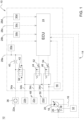
- the single figure shows an embodiment of a device for operating a load-controlled hydraulic supply of an agricultural tractor (not shown).
- the device 14 comprised by a hydraulic system 10 of the agricultural tractor 12 has a hydraulic pump 18 which is fed with hydraulic fluid from a hydraulic reservoir 16 and is adjustable in terms of its displacement volume and has a delivery outlet 20 for supplying a plurality of hydraulic consumers 22a, 22b, 22c, 22d with pressurized hydraulic fluid.
- the displacement volume of the hydraulic pump 18 is adjusted by adjusting a pump swivel angle ⁇ by means of an actuator 26 that can be electrically operated by a control unit 24, in accordance with a load requirement of the hydraulic consumers 22a, 22b, 22c, 22d represented by a respective load reporting pressure LS_P1S, LS_P1B, LS_P2, LS_P3.
- a pressure sensor 30a, 30b, 30c 30d arranged in a respective load reporting line 28a, 28b, 28c, 28d is used to detect the load reporting pressure LS_P1S, LS_P1B, LS_P2, LS_P3, the sensor signals of which are fed to the control unit 24 for evaluation.
- a control loop is formed for the pump swivel angle ⁇ to be set.
- the control unit 24 regulates a system pressure P at the delivery outlet 20 of the hydraulic pump 18 that corresponds to the highest detected load signal pressure LS_P1S, LS_P1B, LS_P2, LS_P3.
- the hydraulic consumers 22a, 22b, 22c, 22d are divided into primary hydraulic consumers 22a, 22b and secondary hydraulic consumers 22c, 22d.
- the primary hydraulic consumers 22a, 22b serve to carry out higher-level hydraulic functions of a hydraulic braking system and a hydrostatic vehicle steering system, whereas subordinate hydraulic functions carried out by the secondary hydraulic consumers 22c, 22d enable the operation of comfort and work functions of the agricultural tractor 12, such as a hydraulic axle or cab suspension, a working hydraulic system including the supply of hydraulically operated work units of an additional or attached device attached to the agricultural tractor 12, but also a hydraulically operable three-point power lift.
- a supply pressure P_P1S, P_P1B, P_P2, P_P3 suitable for operating the respective primary or secondary hydraulic consumer 22a, 22b, 22c, 22d is available on a respective supply line 34a, 34b, 34c, 34d.
- the hydrostatic vehicle steering system included in the agricultural tractor 12 is of conventional design and has a steering orbitrol 36, which is only indicated schematically, and a pressure control valve 38 connected upstream of the steering orbitrol 36, which is actuated in accordance with a pressure difference falling across a throttle element 40 against a restoring force applied by means of a spring element 42 in accordance with a load requirement of the hydrostatic vehicle steering system represented by the load signal pressure LS_P1S.
- the other components of the hydrostatic vehicle steering system such as a steering handle, a hydraulic steering cylinder and the like, are not shown for reasons of clarity.
- the pressure difference is specified for this in the order of 10 to 20 bar.
- the slight but continuous flow of hydraulic fluid through the throttle element 40 in the range of 1 to 5 liters per minute also ensures that a temperature gradient present within the hydraulic circuit of the hydrostatic vehicle steering system during a cold start of the agricultural tractor 12 is quickly reduced, and that jamming, in particular of the steering orbitrol 36, does not occur due to thermal differences or mechanical stresses caused thereby. This is particularly important at low or wintery outside temperatures.
- the primary hydraulic consumers 22a, 22b are directly connected or can be connected to the delivery outlet 20 of the hydraulic pump 18, whereas the secondary hydraulic consumers 22c, 22d are connected or can be connected via intermediate electrically actuated proportional valves 44, 46.
- the secondary hydraulic consumers 22c, 22d are divided into first and second groups 48, 50, whereby each of the two groups 48, 50 can be connected to the delivery outlet 20 of the hydraulic pump 18 via a separate first and second proportional valve 44, 46.
- the representation of two groups 48, 50 is intended to be merely exemplary; a different number of groups or proportional valves can also be provided.
- control unit 24 If the control unit 24 detects that the requested power of the primary or secondary hydraulic consumers 22a, 22b, 22c, 22d exceeds the delivery capacity of the hydraulic pump 18 and/or a hydraulic function assigned to the secondary hydraulic consumers 22c, 22d is inactive, it places the proportional valves 44, 46 in a closed position by controlling a first or second electrical actuator 52, 54. Valve position. This makes it possible to achieve energy savings with regard to inactive hydraulic functions of secondary hydraulic consumers 22c, 22d by specifically throttling the hydraulic volume flow passing through the proportional valves 44, 46 in addition to prioritizing the hydraulic supply of the primary hydraulic consumers 22a, 22b.
- control unit 24 controls the proportional valves 44, 46 in such a way that the hydraulic supply of the primary hydraulic consumers 22a, 22b is prioritized primarily at the expense of secondary hydraulic consumers 22c, 22d with inactive hydraulic functions. Undesirable restrictions on active hydraulic functions due to unnecessary throttling of the hydraulic supply are thus largely avoided.
- An example of this is a hydraulic axle or cab suspension that is inactive when the agricultural tractor 12 is at a standstill.
- proportional valves 44, 46 are moved to their closed position in a predetermined sequence to reduce the power requirement in accordance with the delivery capacity of the hydraulic pump 18.
- the latter is done step by step only to the extent that this is necessary to restore a sufficient hydraulic supply to the primary hydraulic consumers 22a, 22b.
- This allows a further subdivision or gradation of the supply priorities of the secondary hydraulic consumers 22c, 22d to be implemented, so that the operation of certain hydraulic functions can be maintained as far as possible.
- the hydraulic volume flow passing through proportional valves 44, 46 can be designed so that comfort functions are affected first and only then, if necessary, work functions. In less demanding applications, however, it is also conceivable to move both proportional valves 44, 46 synchronously into their (fully) closed position.
- the control unit 24 concludes that the power requirement of the primary or secondary hydraulic consumers 22a, 22b, 22c, 22d exceeds the delivery capacity of the hydraulic pump 18 when the hydraulic pump 18 assumes an operating state indicating a maximum displacement volume and at the same time a permissible pressure difference between the system pressure P present at the delivery outlet 20 of the hydraulic pump 18 and the respective highest load reporting pressure LS_P1S, LS_P1B, LS_P2, LS_P3 is not reached.
- the pressure difference is in the range of 10 to 30 bar and ensures a tolerant regulation of the displacement volume with respect to pressure-reducing line losses of the load reporting pressure LS_P1S, LS_P1B, LS_P2, LS_P3 communicated to the control unit 24.
- a pressure sensor 56 assigned to the delivery outlet 20 of the hydraulic pump 18 is used to detect the system pressure P, the sensor signals of which are fed to the control unit 24 for evaluation.
- the control unit 24 detects the operating state of the hydraulic pump 18, which indicates a maximum displacement volume, by evaluating the pump swivel angle ⁇ .
- the displacement volume increases continuously with the amount of the pump swivel angle ⁇ . Accordingly, the available delivery capacity of the hydraulic pump 18 can be recognized by the fact that that the pump swivel angle ⁇ assumes a fully deflected state in the direction of an end stop. Reaching such an operating state represents a reliable indication of a potentially impending undersupply of the primary hydraulic consumer 22a, 22b. As long as this critical state is not reached, the two proportional valves 44, 46 are in their fully open position.
- control unit 24 limits the system pressure P present at the delivery outlet 20 of the hydraulic pump 18 by adjusting the pump swivel angle ⁇ and thus the displacement volume.
- the system pressure P is limited in accordance with a permissible maximum value in the order of 200 to 250 bar.
- control unit 24 limits the supply pressure P_P1S provided for operating the hydrostatic vehicle steering by adjusting the pump swivel angle ⁇ and thus the displacement volume of the hydraulic pump 18.
- the limitation is set to a value below the permissible maximum value of the system pressure P and is in the order of 170 to 200 bar.
- the current supply pressure P_P1S is derived by the control unit 24 from the load signal pressure LS_P1S communicated to the control unit 24 by the hydrostatic vehicle steering, taking into account the pressure difference falling across the throttle element 40.
Landscapes
- Engineering & Computer Science (AREA)
- Mechanical Engineering (AREA)
- Transportation (AREA)
- Physics & Mathematics (AREA)
- Fluid Mechanics (AREA)
- General Engineering & Computer Science (AREA)
- Chemical & Material Sciences (AREA)
- Combustion & Propulsion (AREA)
- Fluid-Pressure Circuits (AREA)
Applications Claiming Priority (2)
| Application Number | Priority Date | Filing Date | Title |
|---|---|---|---|
| DE102023110913 | 2023-04-27 | ||
| DE102023113309.8A DE102023113309A1 (de) | 2023-04-27 | 2023-05-22 | Vorrichtung zum Betreiben einer lastgesteuerten Hydraulikversorgung eines landwirtschaftlichen Traktors |
Publications (1)
| Publication Number | Publication Date |
|---|---|
| EP4455488A1 true EP4455488A1 (fr) | 2024-10-30 |
Family
ID=92931683
Family Applications (1)
| Application Number | Title | Priority Date | Filing Date |
|---|---|---|---|
| EP24166817.7A Pending EP4455488A1 (fr) | 2023-04-27 | 2024-03-27 | Dispositif de fonctionnement d'un système d'alimentation hydraulique à commande de charge d'un tracteur agricole |
Country Status (2)
| Country | Link |
|---|---|
| US (1) | US12434760B2 (fr) |
| EP (1) | EP4455488A1 (fr) |
Families Citing this family (1)
| Publication number | Priority date | Publication date | Assignee | Title |
|---|---|---|---|---|
| FR3121668B1 (fr) * | 2021-04-09 | 2023-06-02 | Haulotte Group | Nacelle élévatrice, ainsi que procédé de commande d’une nacelle élévatrice |
Citations (8)
| Publication number | Priority date | Publication date | Assignee | Title |
|---|---|---|---|---|
| DE10060187A1 (de) * | 1999-12-16 | 2001-07-12 | Caterpillar Inc | System und Verfahren, um die Sättigung einer Hydraulikventilanordnung zu verhindern |
| DE102008048054A1 (de) * | 2008-09-19 | 2010-03-25 | Still Gmbh | Hydrostatisches Antriebssystem |
| US20110146258A1 (en) * | 2009-08-21 | 2011-06-23 | Josef Peters | Hydraulic Circuit |
| US20120233996A1 (en) * | 2011-03-15 | 2012-09-20 | Quinnell Corey K | System for allocating fluid from multiple pumps to a plurality of hydraulic functions on a priority basis |
| US20130220425A1 (en) * | 2012-02-27 | 2013-08-29 | Paul Edward Pomeroy | Flow sensing based variable pump control technique in a hydraulic system with open center control valves |
| US20140116038A1 (en) * | 2012-11-01 | 2014-05-01 | Husco International, Inc. | Hydraulic system with open loop electrohydraulic pressure compensation |
| US9097268B2 (en) * | 2008-04-11 | 2015-08-04 | Eaton Corporation | Hydraulic system including priority based valve sequencing |
| EP4083444A1 (fr) * | 2021-04-27 | 2022-11-02 | CNH Industrial Italia S.p.A. | Circuit hydraulique pour un véhicule agricole pourvu d'un système anti-saturation et procédé de commande anti-saturation |
Family Cites Families (7)
| Publication number | Priority date | Publication date | Assignee | Title |
|---|---|---|---|---|
| US5918558A (en) * | 1997-12-01 | 1999-07-06 | Case Corporation | Dual-pump, flow-isolated hydraulic circuit for an agricultural tractor |
| US20060196179A1 (en) * | 2005-03-01 | 2006-09-07 | Arun Kesavan | Load-sensing integrated brake and fan hydraulic system |
| WO2009067050A1 (fr) * | 2007-11-21 | 2009-05-28 | Volvo Construction Equipment Ab | Système de détection de charge, machine d'usinage comprenant le système et procédé pour commander une fonction hydraulique |
| DE102010027964A1 (de) * | 2010-04-20 | 2011-10-20 | Deere & Company | Hydraulische Anordnung |
| US10377414B2 (en) * | 2017-02-09 | 2019-08-13 | Deere & Company | Dual margin priority circuit for increased steering capacity |
| FR3121668B1 (fr) * | 2021-04-09 | 2023-06-02 | Haulotte Group | Nacelle élévatrice, ainsi que procédé de commande d’une nacelle élévatrice |
| US20250003430A1 (en) * | 2023-06-30 | 2025-01-02 | Deere & Company | Arrangement for operating a load-controlled hydraulic system of an agricultural tractor |
-
2024
- 2024-03-21 US US18/611,783 patent/US12434760B2/en active Active
- 2024-03-27 EP EP24166817.7A patent/EP4455488A1/fr active Pending
Patent Citations (8)
| Publication number | Priority date | Publication date | Assignee | Title |
|---|---|---|---|---|
| DE10060187A1 (de) * | 1999-12-16 | 2001-07-12 | Caterpillar Inc | System und Verfahren, um die Sättigung einer Hydraulikventilanordnung zu verhindern |
| US9097268B2 (en) * | 2008-04-11 | 2015-08-04 | Eaton Corporation | Hydraulic system including priority based valve sequencing |
| DE102008048054A1 (de) * | 2008-09-19 | 2010-03-25 | Still Gmbh | Hydrostatisches Antriebssystem |
| US20110146258A1 (en) * | 2009-08-21 | 2011-06-23 | Josef Peters | Hydraulic Circuit |
| US20120233996A1 (en) * | 2011-03-15 | 2012-09-20 | Quinnell Corey K | System for allocating fluid from multiple pumps to a plurality of hydraulic functions on a priority basis |
| US20130220425A1 (en) * | 2012-02-27 | 2013-08-29 | Paul Edward Pomeroy | Flow sensing based variable pump control technique in a hydraulic system with open center control valves |
| US20140116038A1 (en) * | 2012-11-01 | 2014-05-01 | Husco International, Inc. | Hydraulic system with open loop electrohydraulic pressure compensation |
| EP4083444A1 (fr) * | 2021-04-27 | 2022-11-02 | CNH Industrial Italia S.p.A. | Circuit hydraulique pour un véhicule agricole pourvu d'un système anti-saturation et procédé de commande anti-saturation |
Also Published As
| Publication number | Publication date |
|---|---|
| US12434760B2 (en) | 2025-10-07 |
| US20240359730A1 (en) | 2024-10-31 |
Similar Documents
| Publication | Publication Date | Title |
|---|---|---|
| EP1642035B1 (fr) | Systeme hydraulique | |
| DE3821416C2 (fr) | ||
| DE102004012382B4 (de) | Hydraulische Anordnung | |
| DE4108915C2 (de) | Hydraulische Einrichtung zur Druckmittelversorgung eines bevorrechtigten Primärlastkreises | |
| DE10164355A1 (de) | Hydraulikbremssystem und Verfahren mit Flußkontrollvorrichtung | |
| EP3444482B1 (fr) | Dispositif de commande de l'état de charge d'au moins un accumulateur de pression | |
| EP3816455A1 (fr) | Dispositif de commande hydraulique destiné à l'alimentation en fluide de pression d'au moins deux consommateurs hydrauliques | |
| DE102018114495A1 (de) | Lastsignalsteuerung einer Arbeitshydraulik eines Anbaugeräts | |
| DE4235707B4 (de) | Hydrostatisches Antriebssystem | |
| EP0515639B1 (fr) | Systeme hydraulique | |
| EP4455488A1 (fr) | Dispositif de fonctionnement d'un système d'alimentation hydraulique à commande de charge d'un tracteur agricole | |
| DE102006003414B3 (de) | Hydraulische Schaltungsanordnung | |
| DE102013214734A1 (de) | Hydraulische Steueranordnung und Verfahren zur Versorgung mehrere Verbraucher damit | |
| EP3398418A1 (fr) | Système hydraulique d'une machine à usage agricole ou de travaux publics | |
| EP3847062B1 (fr) | Structure de régulateur distribuée pour obtenir des propriétés de régulateur optimisées et une durée de vie de soupape accrue | |
| EP4484762A1 (fr) | Agencement pour faire fonctionner un système hydraulique à commande de charge d'un tracteur agricole | |
| DE102023113309A1 (de) | Vorrichtung zum Betreiben einer lastgesteuerten Hydraulikversorgung eines landwirtschaftlichen Traktors | |
| DE102007051525A1 (de) | Hydraulisches Versorgungssystem mit einer Verstellpumpeneinrichtung | |
| DE102017104792A1 (de) | Systeme und Verfahren zur Kalibrierung elektrohydraulischer Ventile | |
| DE69305708T2 (de) | Steuervorrichtung für mehrere hydraulische Verbraucher | |
| WO2005093263A1 (fr) | Systeme de commande hydraulique | |
| EP1954949B1 (fr) | Dispositif hydraulique de commande | |
| EP3918207B1 (fr) | Commande de cylindres de réglage hydrauliques dans les cages de laminage | |
| DE102023117494A1 (de) | Anordnung zum Betreiben eines lastgesteuerten Hydrauliksystems eines landwirtschaftlichen Traktors | |
| EP3093504B1 (fr) | Valve de réglage de débit à 2 voies pressostatique pour des applications hydrauliques et système de valve doté d'une valve de réglage de débit à 2 voies |
Legal Events
| Date | Code | Title | Description |
|---|---|---|---|
| PUAI | Public reference made under article 153(3) epc to a published international application that has entered the european phase |
Free format text: ORIGINAL CODE: 0009012 |
|
| STAA | Information on the status of an ep patent application or granted ep patent |
Free format text: STATUS: THE APPLICATION HAS BEEN PUBLISHED |
|
| AK | Designated contracting states |
Kind code of ref document: A1 Designated state(s): AL AT BE BG CH CY CZ DE DK EE ES FI FR GB GR HR HU IE IS IT LI LT LU LV MC ME MK MT NL NO PL PT RO RS SE SI SK SM TR |
|
| STAA | Information on the status of an ep patent application or granted ep patent |
Free format text: STATUS: REQUEST FOR EXAMINATION WAS MADE |
|
| 17P | Request for examination filed |
Effective date: 20250430 |