EP4455536A2 - Bouchon pour réservoir sous pression et réservoir sous pression pour véhicule à gaz - Google Patents
Bouchon pour réservoir sous pression et réservoir sous pression pour véhicule à gaz Download PDFInfo
- Publication number
- EP4455536A2 EP4455536A2 EP24194452.9A EP24194452A EP4455536A2 EP 4455536 A2 EP4455536 A2 EP 4455536A2 EP 24194452 A EP24194452 A EP 24194452A EP 4455536 A2 EP4455536 A2 EP 4455536A2
- Authority
- EP
- European Patent Office
- Prior art keywords
- thread
- boss
- liner
- pressure tank
- external thread
- Prior art date
- Legal status (The legal status is an assumption and is not a legal conclusion. Google has not performed a legal analysis and makes no representation as to the accuracy of the status listed.)
- Pending
Links
Images

Classifications
-
- F—MECHANICAL ENGINEERING; LIGHTING; HEATING; WEAPONS; BLASTING
- F17—STORING OR DISTRIBUTING GASES OR LIQUIDS
- F17C—VESSELS FOR CONTAINING OR STORING COMPRESSED, LIQUEFIED OR SOLIDIFIED GASES; FIXED-CAPACITY GAS-HOLDERS; FILLING VESSELS WITH, OR DISCHARGING FROM VESSELS, COMPRESSED, LIQUEFIED, OR SOLIDIFIED GASES
- F17C1/00—Pressure vessels, e.g. gas cylinder, gas tank, replaceable cartridge
- F17C1/16—Pressure vessels, e.g. gas cylinder, gas tank, replaceable cartridge constructed of plastics materials
-
- F—MECHANICAL ENGINEERING; LIGHTING; HEATING; WEAPONS; BLASTING
- F17—STORING OR DISTRIBUTING GASES OR LIQUIDS
- F17C—VESSELS FOR CONTAINING OR STORING COMPRESSED, LIQUEFIED OR SOLIDIFIED GASES; FIXED-CAPACITY GAS-HOLDERS; FILLING VESSELS WITH, OR DISCHARGING FROM VESSELS, COMPRESSED, LIQUEFIED, OR SOLIDIFIED GASES
- F17C1/00—Pressure vessels, e.g. gas cylinder, gas tank, replaceable cartridge
- F17C1/02—Pressure vessels, e.g. gas cylinder, gas tank, replaceable cartridge involving reinforcing arrangements
- F17C1/04—Protecting sheathings
- F17C1/06—Protecting sheathings built-up from wound-on bands or filamentary material, e.g. wires
-
- F—MECHANICAL ENGINEERING; LIGHTING; HEATING; WEAPONS; BLASTING
- F17—STORING OR DISTRIBUTING GASES OR LIQUIDS
- F17C—VESSELS FOR CONTAINING OR STORING COMPRESSED, LIQUEFIED OR SOLIDIFIED GASES; FIXED-CAPACITY GAS-HOLDERS; FILLING VESSELS WITH, OR DISCHARGING FROM VESSELS, COMPRESSED, LIQUEFIED, OR SOLIDIFIED GASES
- F17C2201/00—Vessel construction, in particular geometry, arrangement or size
- F17C2201/01—Shape
- F17C2201/0104—Shape cylindrical
- F17C2201/0109—Shape cylindrical with exteriorly curved end-piece
-
- F—MECHANICAL ENGINEERING; LIGHTING; HEATING; WEAPONS; BLASTING
- F17—STORING OR DISTRIBUTING GASES OR LIQUIDS
- F17C—VESSELS FOR CONTAINING OR STORING COMPRESSED, LIQUEFIED OR SOLIDIFIED GASES; FIXED-CAPACITY GAS-HOLDERS; FILLING VESSELS WITH, OR DISCHARGING FROM VESSELS, COMPRESSED, LIQUEFIED, OR SOLIDIFIED GASES
- F17C2201/00—Vessel construction, in particular geometry, arrangement or size
- F17C2201/05—Size
- F17C2201/054—Size medium (>1 m3)
-
- F—MECHANICAL ENGINEERING; LIGHTING; HEATING; WEAPONS; BLASTING
- F17—STORING OR DISTRIBUTING GASES OR LIQUIDS
- F17C—VESSELS FOR CONTAINING OR STORING COMPRESSED, LIQUEFIED OR SOLIDIFIED GASES; FIXED-CAPACITY GAS-HOLDERS; FILLING VESSELS WITH, OR DISCHARGING FROM VESSELS, COMPRESSED, LIQUEFIED, OR SOLIDIFIED GASES
- F17C2201/00—Vessel construction, in particular geometry, arrangement or size
- F17C2201/05—Size
- F17C2201/056—Small (<1 m3)
-
- F—MECHANICAL ENGINEERING; LIGHTING; HEATING; WEAPONS; BLASTING
- F17—STORING OR DISTRIBUTING GASES OR LIQUIDS
- F17C—VESSELS FOR CONTAINING OR STORING COMPRESSED, LIQUEFIED OR SOLIDIFIED GASES; FIXED-CAPACITY GAS-HOLDERS; FILLING VESSELS WITH, OR DISCHARGING FROM VESSELS, COMPRESSED, LIQUEFIED, OR SOLIDIFIED GASES
- F17C2203/00—Vessel construction, in particular walls or details thereof
- F17C2203/01—Reinforcing or suspension means
- F17C2203/011—Reinforcing means
- F17C2203/012—Reinforcing means on or in the wall, e.g. ribs
-
- F—MECHANICAL ENGINEERING; LIGHTING; HEATING; WEAPONS; BLASTING
- F17—STORING OR DISTRIBUTING GASES OR LIQUIDS
- F17C—VESSELS FOR CONTAINING OR STORING COMPRESSED, LIQUEFIED OR SOLIDIFIED GASES; FIXED-CAPACITY GAS-HOLDERS; FILLING VESSELS WITH, OR DISCHARGING FROM VESSELS, COMPRESSED, LIQUEFIED, OR SOLIDIFIED GASES
- F17C2203/00—Vessel construction, in particular walls or details thereof
- F17C2203/06—Materials for walls or layers thereof; Properties or structures of walls or their materials
- F17C2203/0602—Wall structures; Special features thereof
- F17C2203/0604—Liners
-
- F—MECHANICAL ENGINEERING; LIGHTING; HEATING; WEAPONS; BLASTING
- F17—STORING OR DISTRIBUTING GASES OR LIQUIDS
- F17C—VESSELS FOR CONTAINING OR STORING COMPRESSED, LIQUEFIED OR SOLIDIFIED GASES; FIXED-CAPACITY GAS-HOLDERS; FILLING VESSELS WITH, OR DISCHARGING FROM VESSELS, COMPRESSED, LIQUEFIED, OR SOLIDIFIED GASES
- F17C2203/00—Vessel construction, in particular walls or details thereof
- F17C2203/06—Materials for walls or layers thereof; Properties or structures of walls or their materials
- F17C2203/0602—Wall structures; Special features thereof
- F17C2203/0612—Wall structures
- F17C2203/0614—Single wall
- F17C2203/0619—Single wall with two layers
-
- F—MECHANICAL ENGINEERING; LIGHTING; HEATING; WEAPONS; BLASTING
- F17—STORING OR DISTRIBUTING GASES OR LIQUIDS
- F17C—VESSELS FOR CONTAINING OR STORING COMPRESSED, LIQUEFIED OR SOLIDIFIED GASES; FIXED-CAPACITY GAS-HOLDERS; FILLING VESSELS WITH, OR DISCHARGING FROM VESSELS, COMPRESSED, LIQUEFIED, OR SOLIDIFIED GASES
- F17C2203/00—Vessel construction, in particular walls or details thereof
- F17C2203/06—Materials for walls or layers thereof; Properties or structures of walls or their materials
- F17C2203/0634—Materials for walls or layers thereof
- F17C2203/0658—Synthetics
- F17C2203/066—Plastics
-
- F—MECHANICAL ENGINEERING; LIGHTING; HEATING; WEAPONS; BLASTING
- F17—STORING OR DISTRIBUTING GASES OR LIQUIDS
- F17C—VESSELS FOR CONTAINING OR STORING COMPRESSED, LIQUEFIED OR SOLIDIFIED GASES; FIXED-CAPACITY GAS-HOLDERS; FILLING VESSELS WITH, OR DISCHARGING FROM VESSELS, COMPRESSED, LIQUEFIED, OR SOLIDIFIED GASES
- F17C2203/00—Vessel construction, in particular walls or details thereof
- F17C2203/06—Materials for walls or layers thereof; Properties or structures of walls or their materials
- F17C2203/0634—Materials for walls or layers thereof
- F17C2203/0658—Synthetics
- F17C2203/0663—Synthetics in form of fibers or filaments
- F17C2203/0673—Polymers
-
- F—MECHANICAL ENGINEERING; LIGHTING; HEATING; WEAPONS; BLASTING
- F17—STORING OR DISTRIBUTING GASES OR LIQUIDS
- F17C—VESSELS FOR CONTAINING OR STORING COMPRESSED, LIQUEFIED OR SOLIDIFIED GASES; FIXED-CAPACITY GAS-HOLDERS; FILLING VESSELS WITH, OR DISCHARGING FROM VESSELS, COMPRESSED, LIQUEFIED, OR SOLIDIFIED GASES
- F17C2203/00—Vessel construction, in particular walls or details thereof
- F17C2203/06—Materials for walls or layers thereof; Properties or structures of walls or their materials
- F17C2203/0634—Materials for walls or layers thereof
- F17C2203/0658—Synthetics
- F17C2203/0675—Synthetics with details of composition
-
- F—MECHANICAL ENGINEERING; LIGHTING; HEATING; WEAPONS; BLASTING
- F17—STORING OR DISTRIBUTING GASES OR LIQUIDS
- F17C—VESSELS FOR CONTAINING OR STORING COMPRESSED, LIQUEFIED OR SOLIDIFIED GASES; FIXED-CAPACITY GAS-HOLDERS; FILLING VESSELS WITH, OR DISCHARGING FROM VESSELS, COMPRESSED, LIQUEFIED, OR SOLIDIFIED GASES
- F17C2205/00—Vessel construction, in particular mounting arrangements, attachments or identifications means
- F17C2205/03—Fluid connections, filters, valves, closure means or other attachments
- F17C2205/0302—Fittings, valves, filters, or components in connection with the gas storage device
- F17C2205/0305—Bosses, e.g. boss collars
-
- F—MECHANICAL ENGINEERING; LIGHTING; HEATING; WEAPONS; BLASTING
- F17—STORING OR DISTRIBUTING GASES OR LIQUIDS
- F17C—VESSELS FOR CONTAINING OR STORING COMPRESSED, LIQUEFIED OR SOLIDIFIED GASES; FIXED-CAPACITY GAS-HOLDERS; FILLING VESSELS WITH, OR DISCHARGING FROM VESSELS, COMPRESSED, LIQUEFIED, OR SOLIDIFIED GASES
- F17C2205/00—Vessel construction, in particular mounting arrangements, attachments or identifications means
- F17C2205/03—Fluid connections, filters, valves, closure means or other attachments
- F17C2205/0388—Arrangement of valves, regulators, filters
- F17C2205/0394—Arrangement of valves, regulators, filters in direct contact with the pressure vessel
- F17C2205/0397—Arrangement of valves, regulators, filters in direct contact with the pressure vessel on both sides of the pressure vessel
-
- F—MECHANICAL ENGINEERING; LIGHTING; HEATING; WEAPONS; BLASTING
- F17—STORING OR DISTRIBUTING GASES OR LIQUIDS
- F17C—VESSELS FOR CONTAINING OR STORING COMPRESSED, LIQUEFIED OR SOLIDIFIED GASES; FIXED-CAPACITY GAS-HOLDERS; FILLING VESSELS WITH, OR DISCHARGING FROM VESSELS, COMPRESSED, LIQUEFIED, OR SOLIDIFIED GASES
- F17C2209/00—Vessel construction, in particular methods of manufacturing
- F17C2209/21—Shaping processes
- F17C2209/2109—Moulding
- F17C2209/2127—Moulding by blowing
-
- F—MECHANICAL ENGINEERING; LIGHTING; HEATING; WEAPONS; BLASTING
- F17—STORING OR DISTRIBUTING GASES OR LIQUIDS
- F17C—VESSELS FOR CONTAINING OR STORING COMPRESSED, LIQUEFIED OR SOLIDIFIED GASES; FIXED-CAPACITY GAS-HOLDERS; FILLING VESSELS WITH, OR DISCHARGING FROM VESSELS, COMPRESSED, LIQUEFIED, OR SOLIDIFIED GASES
- F17C2209/00—Vessel construction, in particular methods of manufacturing
- F17C2209/22—Assembling processes
- F17C2209/228—Assembling processes by screws, bolts or rivets
-
- F—MECHANICAL ENGINEERING; LIGHTING; HEATING; WEAPONS; BLASTING
- F17—STORING OR DISTRIBUTING GASES OR LIQUIDS
- F17C—VESSELS FOR CONTAINING OR STORING COMPRESSED, LIQUEFIED OR SOLIDIFIED GASES; FIXED-CAPACITY GAS-HOLDERS; FILLING VESSELS WITH, OR DISCHARGING FROM VESSELS, COMPRESSED, LIQUEFIED, OR SOLIDIFIED GASES
- F17C2221/00—Handled fluid, in particular type of fluid
- F17C2221/01—Pure fluids
- F17C2221/012—Hydrogen
-
- F—MECHANICAL ENGINEERING; LIGHTING; HEATING; WEAPONS; BLASTING
- F17—STORING OR DISTRIBUTING GASES OR LIQUIDS
- F17C—VESSELS FOR CONTAINING OR STORING COMPRESSED, LIQUEFIED OR SOLIDIFIED GASES; FIXED-CAPACITY GAS-HOLDERS; FILLING VESSELS WITH, OR DISCHARGING FROM VESSELS, COMPRESSED, LIQUEFIED, OR SOLIDIFIED GASES
- F17C2223/00—Handled fluid before transfer, i.e. state of fluid when stored in the vessel or before transfer from the vessel
- F17C2223/01—Handled fluid before transfer, i.e. state of fluid when stored in the vessel or before transfer from the vessel characterised by the phase
- F17C2223/0107—Single phase
- F17C2223/0123—Single phase gaseous, e.g. CNG, GNC
-
- F—MECHANICAL ENGINEERING; LIGHTING; HEATING; WEAPONS; BLASTING
- F17—STORING OR DISTRIBUTING GASES OR LIQUIDS
- F17C—VESSELS FOR CONTAINING OR STORING COMPRESSED, LIQUEFIED OR SOLIDIFIED GASES; FIXED-CAPACITY GAS-HOLDERS; FILLING VESSELS WITH, OR DISCHARGING FROM VESSELS, COMPRESSED, LIQUEFIED, OR SOLIDIFIED GASES
- F17C2223/00—Handled fluid before transfer, i.e. state of fluid when stored in the vessel or before transfer from the vessel
- F17C2223/03—Handled fluid before transfer, i.e. state of fluid when stored in the vessel or before transfer from the vessel characterised by the pressure level
- F17C2223/036—Very high pressure (>80 bar)
-
- F—MECHANICAL ENGINEERING; LIGHTING; HEATING; WEAPONS; BLASTING
- F17—STORING OR DISTRIBUTING GASES OR LIQUIDS
- F17C—VESSELS FOR CONTAINING OR STORING COMPRESSED, LIQUEFIED OR SOLIDIFIED GASES; FIXED-CAPACITY GAS-HOLDERS; FILLING VESSELS WITH, OR DISCHARGING FROM VESSELS, COMPRESSED, LIQUEFIED, OR SOLIDIFIED GASES
- F17C2260/00—Purposes of gas storage and gas handling
- F17C2260/01—Improving mechanical properties or manufacturing
- F17C2260/011—Improving strength
-
- F—MECHANICAL ENGINEERING; LIGHTING; HEATING; WEAPONS; BLASTING
- F17—STORING OR DISTRIBUTING GASES OR LIQUIDS
- F17C—VESSELS FOR CONTAINING OR STORING COMPRESSED, LIQUEFIED OR SOLIDIFIED GASES; FIXED-CAPACITY GAS-HOLDERS; FILLING VESSELS WITH, OR DISCHARGING FROM VESSELS, COMPRESSED, LIQUEFIED, OR SOLIDIFIED GASES
- F17C2270/00—Applications
- F17C2270/01—Applications for fluid transport or storage
- F17C2270/0165—Applications for fluid transport or storage on the road
- F17C2270/0168—Applications for fluid transport or storage on the road by vehicles
- F17C2270/0171—Trucks
-
- F—MECHANICAL ENGINEERING; LIGHTING; HEATING; WEAPONS; BLASTING
- F17—STORING OR DISTRIBUTING GASES OR LIQUIDS
- F17C—VESSELS FOR CONTAINING OR STORING COMPRESSED, LIQUEFIED OR SOLIDIFIED GASES; FIXED-CAPACITY GAS-HOLDERS; FILLING VESSELS WITH, OR DISCHARGING FROM VESSELS, COMPRESSED, LIQUEFIED, OR SOLIDIFIED GASES
- F17C2270/00—Applications
- F17C2270/01—Applications for fluid transport or storage
- F17C2270/0165—Applications for fluid transport or storage on the road
- F17C2270/0184—Fuel cells
-
- Y—GENERAL TAGGING OF NEW TECHNOLOGICAL DEVELOPMENTS; GENERAL TAGGING OF CROSS-SECTIONAL TECHNOLOGIES SPANNING OVER SEVERAL SECTIONS OF THE IPC; TECHNICAL SUBJECTS COVERED BY FORMER USPC CROSS-REFERENCE ART COLLECTIONS [XRACs] AND DIGESTS
- Y02—TECHNOLOGIES OR APPLICATIONS FOR MITIGATION OR ADAPTATION AGAINST CLIMATE CHANGE
- Y02E—REDUCTION OF GREENHOUSE GAS [GHG] EMISSIONS, RELATED TO ENERGY GENERATION, TRANSMISSION OR DISTRIBUTION
- Y02E60/00—Enabling technologies; Technologies with a potential or indirect contribution to GHG emissions mitigation
- Y02E60/30—Hydrogen technology
- Y02E60/32—Hydrogen storage
Definitions
- the invention relates to a pressure tank for storing gas for installation in a gas-powered vehicle, wherein the pressure tank has a rotationally symmetrical, elongated shape that is cylindrical in the middle area and closed at both ends with curved pole caps.
- the pressure tank has a wall that encloses a cavity for storing the gas, as well as a metal connecting piece, a so-called boss, on each of the pole caps, wherein the wall comprises a reinforcing layer made of fiber-reinforced plastic and an internal liner for sealing.
- Gas-powered vehicles for example, have a gas engine or a fuel cell with an electric motor as a drive.
- the gas which can be hydrogen
- the tank under high pressure. Pressures of over 200 bar, often up to 600 bar and sometimes even up to 700 or 875 bar are typical for such pressure tanks. This means that the pressure tank not only has to be gas-tight under this pressure, but also that it needs to be highly mechanically stable.
- Pressure tanks for gas-powered vehicles are known in the prior art. These pressure tanks have a wall that includes an internal liner, for example made of thermoplastic, for sealing and a reinforcing layer made of fiber-reinforced plastic to create mechanical stability.
- the reinforcing layer is preferably wound and designed as a CFRP layer.
- CFRP stands for carbon fiber reinforced plastic.
- the boss has a through hole and a connection thread. At least one of the two bosses has a tank fitting connected to it, which allows the pressure tank to be filled or gas to be removed in a controlled manner. On the other boss, the through hole is sealed with a cap or another tank fitting or safety valve is provided there.
- connection between the boss and the liner in the state of the art.
- a positive connection between the liner (referred to as the inner lining) and the boss (referred to as the annular flange) can be used.
- positive connections such as dovetail connections, can currently only be produced if the pole caps of the liner are manufactured by injection molding or a similar process.
- the boss (referred to as the base body or metal body) is screwed onto the liner collar (referred to as the inner container or core container).
- the boss has an internal thread for this purpose. Sealing is ensured by a metal cylinder screwed into the boss, which has O-ring seals. The liner is thus clamped between the boss on the outside and the metal cylinder on the inside. The boss is then wrapped on the outside with the reinforcement layer made of CFRP.
- WO 2018/217529 A1 It is known to design the boss with an external thread and to connect it to the liner via a matching internal thread.
- the reinforcement layer is usually produced using a winding process.
- the liner which is already connected to the boss as a preliminary product, is clamped into a winding machine and set in rotation. The torque is introduced into the liner via the boss(es).
- the liner is wrapped with fiber bands or fiber rovings, whereby, due to the process, high tensile forces act tangentially on the liner due to the tension of the rovings or fiber bands.
- the object of the invention is to develop a pressure tank or a boss for a pressure tank that has a better connection between liner and boss, so that even new, larger pressure tanks can be manufactured easily and reliably.
- the pressure tank according to claim 1 is characterized in that the boss has an external thread that can be connected to a matching internal thread of the liner and that is arranged concentrically to its longitudinal axis L.
- the boss has an external thread that can be connected to a matching internal thread of the liner and that is arranged concentrically to its longitudinal axis L.
- the external thread on the boss and the resulting good connection between boss and liner ensure that the liner is free of forces on the sealing surface between liner and boss. This is possible because the external thread is radially further away from the longitudinal axis t than the sealing surface and thus keeps any torque load from the sealing surface further inside.
- the increased diameter at the connection between boss and liner also means that the sealing surface further inside between boss and liner can be enlarged and designed to seal better.
- the pressure tank according to the invention is characterized in that it comprises two bosses according to the invention. Both bosses are therefore connected via an external thread to the liner, which has a matching internal thread.
- a pressure tank can be manufactured, for example, by first producing a pre-product.
- the liner is made from a thermoplastic, in particular polyamide, for example using a blow molding process, and then the two bosses are screwed into the liner.
- the pre-product made of liner and boss is wrapped with tapes made of fiber-reinforced plastic, in particular CFRP (carbon fiber-reinforced plastic), to form the reinforcement layer of the pressure tank.
- the tapes are preferably already impregnated with a suitable plastic resin (so-called Towpreg), which is cured after winding.
- Towpreg a suitable plastic resin
- Towpregs lead to even higher tensile forces during winding, since they require higher pull-off forces for unwinding from the supply spools due to the tough resin.
- the connection to the liner is significantly more resilient than with connections according to the state of the art, so that trouble-free wrapping without damage to the connection points is guaranteed in every case.
- the external thread on one boss is designed as a right-hand thread and the external thread on the other boss is designed as a left-hand thread, with the liner having a corresponding internal thread on each side.
- both boss-liner connections can absorb higher rotational forces in a common direction of rotation and are thus better protected against unscrewing during the winding process.
- the drive during the winding process can be carried out via both bosses.
- a particularly good connection that is also space-saving and therefore weight-saving is achieved when the external thread has at least 4 to a maximum of 10 threads.
- a thread is considered to be a groove that runs once around the circumference and is made up of a thread elevation with an adjacent thread depression.
- the external thread is designed as a cylindrical thread and has a diameter based on the tips of the thread elevations of at least 60 mm, preferably at least 90 mm, and a maximum of 180 mm. This ensures that the connection can withstand sufficient loads for the subsequent winding process and at the same time allows the boss to be not too heavy.
- the external thread has at one end at least half a thread turn with a thread elevation that is lower than the other thread elevations, and at the other end at least half a thread turn, preferably at least a full thread turn with a thread recess that is smaller than the other thread recesses.
- the height of the thread elevations tapers off linearly towards one end of the thread. This means that the thread elevation is continuously reduced towards the end.
- the depth of the thread recesses tapers off linearly towards the other end of the thread. This means that the thread recess is continuously reduced towards the end.
- the thread pitch can be adapted locally to the thread elevation or thread recess.
- the thread with the lower thread elevation is located at the end facing the cavity, and the thread with the smaller thread depression is located at the end facing the reinforcement layer.
- the internal thread in the liner is designed accordingly in the opposite direction.
- Such a special thread provides a positive connection between the boss and liner and increases the stability of the connection. If the boss is screwed into the liner, the rotational position of the boss to the liner can be set with repeatable accuracy by changing the half or full threads at the respective end of the thread. This means that the external thread on the boss is exactly filled by the internal thread of the liner when screwed in, thus creating a highly resilient connection.
- even small manufacturing inaccuracies and the resultant boss not being fully screwed in mean that there are no large gaps in the thread between the boss and the liner, as the respective thread recesses at the end of the thread have a smaller volume. This is an advantage, as if there are larger gaps in the connection, the enormous internal pressure would otherwise cause high shear forces to act on the liner and damage it.
- a preferred way to securely mount the pressure tank in a vehicle or in a tank module is to design the boss in such a way that the boss includes a neck area for receiving in a bracket.
- the bracket encloses the neck area of the boss and can thus bear the weight of the pressure tank.
- the neck region has a length which is at least 50% of the outer diameter, measured at the thinnest point of the neck region, wherein the length is preferably between 40 mm and 80 mm and wherein the neck region is particularly preferably provided with a cylindrical outer contour. This means that the neck area is long enough to form a stable mount in the holder.
- the boss also has an annular sealing surface which is arranged perpendicular to the longitudinal axis (L) or which forms an angle with the longitudinal axis (L) of between 70° and 110°.
- the liner can also be pressed against this sealing surface, for example with the aid of a spring element, so that the seal is further improved.
- the boss can have a screw thread which is designed as an internal thread and through which a bushing can be screwed in, which serves to press the liner against a sealing surface of the boss with the aid of a spring element.
- the two bosses can also be designed with an external thread in the same direction (both with a right-hand thread or both with a left-hand thread). This means that torque forces can be absorbed in both directions of rotation on the pre-product and the pressure tank, with one of the bosses absorbing the torque at a time.
- the internal threads of the liner that match the external thread are machined in the liner. This allows a precisely fitting internal thread to be created, which increases the tightness and load-bearing capacity of the connection. In addition, the risk of cracks forming when screwing in the bosses is reduced, as the external thread does not have to cut into the surface of the liner.
- the seal between liner and boss can be improved if a bushing connected to the boss, a pressure ring and a spring element are provided for sealing, designed in such a way that the spring element is supported on the bushing and presses the pressure ring against the liner and thus presses the liner against a sealing surface of the boss.
- the bushing is attached to the boss via a screw thread, in particular in such a way that the force with which the pressure ring is pressed can be changed.
- the bushing can have an external thread that engages an internal thread on the boss.
- the socket can be attached to the boss using a clamp.
- the clamp must be designed in such a way that it cannot be released by the spring force.
- the bushing that can be connected to the boss, the pressure ring and the spring element can be arranged on the so-called blow mandrel when the liner is manufactured using the blow molding process.
- the plastic for the liner is extruded from a nozzle, initially creating a hose.
- two or more parts of the blow molding tool are brought together to form a cavity in the shape of the liner to be formed for the pressure tank.
- the extruded hose is located in this cavity. Gas is blown into the hose via the so-called blow mandrel, a mouthpiece, which causes it to adhere to the inside of the blow molding tool. This gives the liner the desired shape.
- the liner can be demolded.
- the blow mandrel is removed.
- the liner is preferably made from a thermoplastic material, for example polyamide. Thermoplastic plastic solidifies after cooling. This makes it possible for the pressure ring and the spring element to be located on the inside of the liner after the liner has been manufactured, whereby the spring element can rest on the bushing and press the pressure ring against the liner and the liner against a surface of a boss when the bushing is later connected to the boss.
- a significant advantage of this design is that due to the spring element and the two-part design with bushing and pressure ring, a preload for sealing on the sealing surface between liner and boss can be applied.
- the sealing surface is located in the area where the liner is pressed against the boss. Due to the pre-tensioning created in this way, sufficient tightness is always ensured, for example, even with low internal pressure or expansion due to temperature differences. By adjusting the spring force, over-pressing of the liner and thus deformation that leads to leaks can be avoided.
- a spring element is understood here to be an element that can exert sufficient elastic spring force when compressed.
- it can be designed as a ring-shaped element made of spring steel, which has so-called spring wings; in particular, the spring element can have a U-shaped or V-shaped cross-section.
- the spring element can also be formed from several leaf springs or spiral springs, which are arranged between the bushing and the pressure ring. Other types and shapes of springs can also be used here.
- Other spring materials that can be used include, for example, elastic polymers (elastomers or cross-linked thermoplastics) or spring elements made of fiber-reinforced plastics.
- the pressure ring can be moved relative to the bushing in the direction of the longitudinal axis L. This means that the pressure ring can be made so rigid that an even pressure is applied across the sealing surface and thus a reliable seal is achieved.
- the bushing is arranged in such a way that it has no surface contact with the liner.
- the pressure for sealing is only transmitted via the surface of the pressure ring.
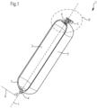
- the Fig.1 shows the pressure tank 1 with a boss 4,4' on each of the two pole caps.
- a tank fitting 5 for filling and controlled gas removal is screwed into the boss 4.
- the boss 4' is sealed with a closure. Alternatively, it can accommodate a safety valve.
- the wall of the pressure tank 1 encloses the cavity 2 and is formed by an internal liner 3 and a reinforcing layer 6.
- the liner 3 is preferably made of thermoplastic such as polyamide and is produced in the blow molding process according to the invention.
- the reinforcing layer 6 is produced by a winding process with tapes made of fiber-reinforced plastic, preferably CFRP.
- the pressure tank 1 is rotationally symmetrical about the longitudinal axis L.
- the bosses 4.4' are screwed to the liner 3 via an external thread.
- one boss 4 has a right-hand thread and the other boss 4' a left-hand thread.
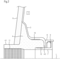
- Fig.2 shows the section B of the pressure tank 1 in an enlarged view, so that the inventive design for the improved connection between boss and liner can be seen.
- the boss 4 has the external thread 10.
- the liner 3 has a corresponding matching internal thread. This is preferably produced by machining after the liner 3 has been produced, for example, in a blow molding process. Due to the larger diameter of the external thread 10, the connection can withstand greater loads. This enables trouble-free wrapping with the tapes for the reinforcement layer 6.
- the boss also has the sealing surface 4.2.
- the pressure ring 8 and the spring element 9 are located inside the liner 3, i.e. in the cavity 2.
- the spring element 9 is pre-tensioned via the bushing 7, which is connected to the boss 4, and presses the pressure ring 8 onto the liner 3 and thus the liner 3 onto the boss 4.
- the connection between the boss 4 and the bushing 7 is made via the screw thread 12, with a corresponding external thread on the bushing 7.
- the bushing 7 and the liner 3 do not touch one another flatly; there is only some contact on the front surface of the liner 3.
- the liner 3 is only pressed onto the sealing surface 4.2 of the boss via the pressure ring 8.
- This pressure ring 8 is movable relative to the bushing 7 and can be moved in the direction of the longitudinal axis L. Together they enclose the spring element 9, which is therefore well protected. This also makes the components easy to assemble. For this purpose, a special tool is used which can be inserted through the through hole of the Boss 4.
- the surface of the pressure ring 8, which is pressed against the liner 3, and the surface of the liner 3, which is pressed against the boss 4, are essentially perpendicular to the longitudinal axis L.
- the collar of the bushing 7, on which the spring element 9 is supported is essentially perpendicular to the longitudinal axis L. arranged.
- the spring force of the spring element 9 is thus transferred completely via the pressure ring 8 to the sealing surface between the boss 4 and the liner 3 through the screw connection 12.
- the area of the boss 4 in which the pressure ring 8 presses the liner 3 onto the boss 4 is referred to as the sealing surface 4.2 or throttling point.
- the sealing and thus the throttling of the internal gas pressure in the pressure tank is achieved by pressing the liner 3 onto the boss 4 due to the spring force of the spring element 9 and due to the internal gas pressure itself.
- the pressure ring 8 is preferably shaped on the side against which the spring element 9 rests so that the largest possible contact surface is used for force transmission.
- the pressure ring 8 has a curved shape that corresponds to the curve of the spring ring with a U-shaped cross section.
- the Boss 4 has an internal thread 11, through which a tank fitting, a safety valve or a closure can be screwed in.
- the Boss has a neck area 4.1, which is suitable for being held in a holder in order to attach the pressure tank in a vehicle.
- the solution according to the invention with the external thread 10 on the boss for a reliable and stable connection with the liner 3 can also be used in versions of the boss other than those shown here.
- the seal between liner 3 and boss 4 can be made on the sealing surface 4.2 be improved by further measures or the sealing can be carried out in a different way than with the pressure ring 8 shown.
- the boss 4 In the Fig.3 an embodiment of the boss 4 according to the invention is shown.
- the sealing surface 4.2 Between the neck area 4.1 and the external thread 10 there is a collar, which is later wrapped with the tapes for the reinforcement layer and which is arranged in the finished pressure tank between the reinforcement layer and the liner.
- the external thread 10 is preferably a cylindrical thread.
- the diameter of the external thread 10 is preferably between 60 mm and 180 mm.
- the sealing surface 4.2 is designed so that the liner is pressed against it by suitable devices, thus creating a throttle point that seals against the internal pressure.
- ring-shaped elevations of a few tenths of a millimeter in height can be provided on the sealing surface 4.2. These elevations press into the adjacent liner and thus ensure better sealing.
- the boss has the neck area 4.1, which is suitable for being accommodated in a bracket in order to fix the pressure tank in a vehicle.
- the neck area is provided with a cylindrical outer contour and has at least a length b of at least 50% of its outer diameter a.
- the Fig.4 shows a special external thread 10 of the boss 4 according to the invention in a sectional view.
- the thread elevations 10.1 extend to the external diameter d and have the same height except for the thread elevation 10.4.
- the thread recesses 10.2 also have the same depth except for the thread recess 10.3.
- a groove running around once from the thread elevation 10.1 and the thread recess 10.2 each form a thread turn.
- the external thread 10 shown here has 7 thread turns.
- a half or a full thread at one end of the external thread has a thread elevation 10.4 with a lower height.
- the height of the respective thread elevations can decrease linearly towards this end of the external thread. This end faces the cavity 2 of the pressure tank.
- a half or a full thread is arranged, which has the thread recess 10.3 with a smaller depth.
- the thread recesses can be designed to decrease linearly towards this end of the external thread.
Landscapes
- Engineering & Computer Science (AREA)
- Mechanical Engineering (AREA)
- General Engineering & Computer Science (AREA)
- Filling Or Discharging Of Gas Storage Vessels (AREA)
- Pressure Vessels And Lids Thereof (AREA)
Applications Claiming Priority (3)
| Application Number | Priority Date | Filing Date | Title |
|---|---|---|---|
| DE102020134624.7A DE102020134624A1 (de) | 2020-12-22 | 2020-12-22 | Boss für einen Drucktank und Drucktank für gasbetriebenes Fahrzeug |
| PCT/EP2021/084093 WO2022135872A1 (fr) | 2020-12-22 | 2021-12-03 | Bouchon pour réservoir sous pression et réservoir sous pression pour véhicule à gaz |
| EP21835990.9A EP4267880A1 (fr) | 2020-12-22 | 2021-12-03 | Bouchon pour réservoir sous pression et réservoir sous pression pour véhicule à gaz |
Related Parent Applications (1)
| Application Number | Title | Priority Date | Filing Date |
|---|---|---|---|
| EP21835990.9A Division EP4267880A1 (fr) | 2020-12-22 | 2021-12-03 | Bouchon pour réservoir sous pression et réservoir sous pression pour véhicule à gaz |
Publications (2)
| Publication Number | Publication Date |
|---|---|
| EP4455536A2 true EP4455536A2 (fr) | 2024-10-30 |
| EP4455536A3 EP4455536A3 (fr) | 2025-01-22 |
Family
ID=79230635
Family Applications (2)
| Application Number | Title | Priority Date | Filing Date |
|---|---|---|---|
| EP24194452.9A Pending EP4455536A3 (fr) | 2020-12-22 | 2021-12-03 | Bous pour réservoir sous pression et réservoir sous pression pour véhicule fonctionnant au gaz |
| EP21835990.9A Pending EP4267880A1 (fr) | 2020-12-22 | 2021-12-03 | Bouchon pour réservoir sous pression et réservoir sous pression pour véhicule à gaz |
Family Applications After (1)
| Application Number | Title | Priority Date | Filing Date |
|---|---|---|---|
| EP21835990.9A Pending EP4267880A1 (fr) | 2020-12-22 | 2021-12-03 | Bouchon pour réservoir sous pression et réservoir sous pression pour véhicule à gaz |
Country Status (6)
| Country | Link |
|---|---|
| EP (2) | EP4455536A3 (fr) |
| JP (1) | JP2024500177A (fr) |
| KR (1) | KR20230118999A (fr) |
| CN (1) | CN116710694A (fr) |
| DE (1) | DE102020134624A1 (fr) |
| WO (1) | WO2022135872A1 (fr) |
Families Citing this family (2)
| Publication number | Priority date | Publication date | Assignee | Title |
|---|---|---|---|---|
| CN119879067B (zh) * | 2024-01-26 | 2025-10-28 | 中国长江电力股份有限公司 | 一种防泄漏的加氢装置及其工作方法 |
| DE102024123049A1 (de) * | 2024-08-13 | 2026-02-19 | Voith Hystech Gmbh | Drucktank für gasbetriebenes Fahrzeug |
Citations (5)
| Publication number | Priority date | Publication date | Assignee | Title |
|---|---|---|---|---|
| EP0550951A1 (fr) | 1992-01-10 | 1993-07-14 | Technical Products Group, Inc. | Coulot et coupelle d'un réservoir sous pression à filament enroulé |
| EP2115343A1 (fr) | 2007-03-08 | 2009-11-11 | Xperion GmbH | Contenant sous pression destiné à stocker des fluides liquides ou gazeux |
| DE102011010685A1 (de) | 2010-02-08 | 2011-08-11 | Magna Steyr Fahrzeugtechnik Ag & Co. Kg | Druckbehälter |
| WO2011103687A1 (fr) | 2010-02-26 | 2011-09-01 | Dynetek Industries Ltd. | Système d'étanchéité pour la sortie d'une bouteille de gaz comprimé revêtue intérieurement de plastique |
| WO2018217529A1 (fr) | 2017-05-24 | 2018-11-29 | Hexagon Technology As | Bossage fileté pour récipient sous pression |
Family Cites Families (9)
| Publication number | Priority date | Publication date | Assignee | Title |
|---|---|---|---|---|
| US5798156A (en) * | 1996-06-03 | 1998-08-25 | Mitlitsky; Fred | Lightweight bladder lined pressure vessels |
| DE102014000621B4 (de) * | 2014-01-18 | 2022-08-11 | Cellcentric Gmbh & Co. Kg | Druckgasbehälter |
| US10088104B2 (en) | 2014-07-28 | 2018-10-02 | Quantum Fuel Systems Llc | Composite pressure tank boss mounting with pressure relief |
| KR101806643B1 (ko) * | 2015-12-16 | 2017-12-07 | 현대자동차주식회사 | 다중 실링 구조를 갖는 노즐 및 이를 포함하는 압력 용기 |
| KR20170130649A (ko) * | 2016-05-18 | 2017-11-29 | 일진복합소재 주식회사 | 압력용기 |
| KR101856334B1 (ko) * | 2016-06-29 | 2018-05-09 | 현대자동차주식회사 | 기밀한 노즐 구조를 갖는 복합재 용기 |
| CN109210365B (zh) * | 2018-10-30 | 2020-12-29 | 亚普汽车部件股份有限公司 | 高压复合容器的密封结构及高压复合容器 |
| DE102018009829B4 (de) | 2018-12-14 | 2020-09-17 | Emano Kunststofftechnik Gmbh | Druckbehälter und Verfahren zur Herstellung des Druckbehälters |
| DE102020134633A1 (de) * | 2020-12-22 | 2022-06-23 | Voith Patent Gmbh | Drucktank für gasbetriebenes Fahrzeug |
-
2020
- 2020-12-22 DE DE102020134624.7A patent/DE102020134624A1/de active Pending
-
2021
- 2021-12-03 CN CN202180085249.5A patent/CN116710694A/zh active Pending
- 2021-12-03 EP EP24194452.9A patent/EP4455536A3/fr active Pending
- 2021-12-03 WO PCT/EP2021/084093 patent/WO2022135872A1/fr not_active Ceased
- 2021-12-03 EP EP21835990.9A patent/EP4267880A1/fr active Pending
- 2021-12-03 JP JP2023538110A patent/JP2024500177A/ja active Pending
- 2021-12-03 KR KR1020237024531A patent/KR20230118999A/ko active Pending
Patent Citations (5)
| Publication number | Priority date | Publication date | Assignee | Title |
|---|---|---|---|---|
| EP0550951A1 (fr) | 1992-01-10 | 1993-07-14 | Technical Products Group, Inc. | Coulot et coupelle d'un réservoir sous pression à filament enroulé |
| EP2115343A1 (fr) | 2007-03-08 | 2009-11-11 | Xperion GmbH | Contenant sous pression destiné à stocker des fluides liquides ou gazeux |
| DE102011010685A1 (de) | 2010-02-08 | 2011-08-11 | Magna Steyr Fahrzeugtechnik Ag & Co. Kg | Druckbehälter |
| WO2011103687A1 (fr) | 2010-02-26 | 2011-09-01 | Dynetek Industries Ltd. | Système d'étanchéité pour la sortie d'une bouteille de gaz comprimé revêtue intérieurement de plastique |
| WO2018217529A1 (fr) | 2017-05-24 | 2018-11-29 | Hexagon Technology As | Bossage fileté pour récipient sous pression |
Also Published As
| Publication number | Publication date |
|---|---|
| KR20230118999A (ko) | 2023-08-14 |
| JP2024500177A (ja) | 2024-01-04 |
| US20250264189A1 (en) | 2025-08-21 |
| DE102020134624A1 (de) | 2022-06-23 |
| WO2022135872A1 (fr) | 2022-06-30 |
| EP4455536A3 (fr) | 2025-01-22 |
| EP4267880A1 (fr) | 2023-11-01 |
| CN116710694A (zh) | 2023-09-05 |
Similar Documents
| Publication | Publication Date | Title |
|---|---|---|
| EP4267882B1 (fr) | Réservoir sous pression pour véhicule fonctionnant au gaz | |
| DE60127940T2 (de) | Faserverstärkter druckbehälter und herstellungsverfahren dafür | |
| EP1977153B1 (fr) | Réservoir sous pression | |
| EP3786511B1 (fr) | Récipient sous pression | |
| DE102021100139A1 (de) | Verfahren zur herstellung eines hochdrucktanks | |
| DE102011116553A1 (de) | Verfahren zur Herstellung eines Verbund-Druckbehälters sowie Verbund-Druckbehälter | |
| DE3331021A1 (de) | Stangenfoermiger hohlkoerper zur uebertragung von druck-, zug-, biege- und verdrehkraeften, verfahren zu seiner herstellung sowie vorrichtung zur durchfuehrung des beschriebenen verfahrens | |
| EP3012507B1 (fr) | Procédé et outil destinés à la fabrication d'un récipient sous pression et récipient sous pression | |
| DE102016201477A1 (de) | Druckbehälter sowie Verfahren zur Herstellung eines Druckbehälters | |
| EP4455536A2 (fr) | Bouchon pour réservoir sous pression et réservoir sous pression pour véhicule à gaz | |
| DE102015102440B4 (de) | Verfahren zur Herstellung eines Faserverbund-Hohlkörpers mit helixförmiger Kontur | |
| DE102017207498A1 (de) | Druckbehälterherstellung mit faserverstärkter Kappe | |
| DE60210364T2 (de) | Verfahren zur Herstellung eines Hochdruckspeichers insbesondere für ein Raumfahrzeug und nach dem Verfahren hergestellter Hochdruckspeicher | |
| DE102017201420B4 (de) | Tank, insbesondere Drucktank, insbesondere Wasserstoff-Drucktank | |
| DE102011120041A1 (de) | Druckbehälter zur Speicherung von fluiden Medien und Verfahren zur Herstellung eines derartigen Druckbehälters sowie Anschlussstück für einen Druckbehälter | |
| WO2024175509A1 (fr) | Réservoir sous pression pour véhicule fonctionnant au gaz | |
| EP1506921B1 (fr) | Dispositif rétractable pour un sous-marin et méthode de fabrication | |
| DE102017211419A1 (de) | Verfahren zur Herstellung eines faserverstärkten Bauteils für ein Kraftfahrzeug und faserverstärktes Bauteil | |
| EP3786512B1 (fr) | Procédé de fabrication d'un récipient sous pression et récipient sous pression | |
| DE102009024795A1 (de) | Wasserstofftank in einem Kraftfahrzeug | |
| DE102024123048A1 (de) | Drucktank für gasbetriebenes Fahrzeug | |
| WO2026037577A1 (fr) | Réservoir sous pression pour véhicule fonctionnant au gaz | |
| DE102024123050A1 (de) | Drucktank für gasbetriebenes Fahrzeug | |
| DE102024123051A1 (de) | Drucktank für gasbetriebenes Fahrzeug | |
| WO2023213465A1 (fr) | Procédé de fabrication d'un renfort de capuchon polaire et récipient sous pression, et récipient sous pression ayant un renfort de capuchon polaire |
Legal Events
| Date | Code | Title | Description |
|---|---|---|---|
| PUAI | Public reference made under article 153(3) epc to a published international application that has entered the european phase |
Free format text: ORIGINAL CODE: 0009012 |
|
| STAA | Information on the status of an ep patent application or granted ep patent |
Free format text: STATUS: THE APPLICATION HAS BEEN PUBLISHED |
|
| AC | Divisional application: reference to earlier application |
Ref document number: 4267880 Country of ref document: EP Kind code of ref document: P |
|
| AK | Designated contracting states |
Kind code of ref document: A2 Designated state(s): AL AT BE BG CH CY CZ DE DK EE ES FI FR GB GR HR HU IE IS IT LI LT LU LV MC MK MT NL NO PL PT RO RS SE SI SK SM TR |
|
| PUAL | Search report despatched |
Free format text: ORIGINAL CODE: 0009013 |
|
| AK | Designated contracting states |
Kind code of ref document: A3 Designated state(s): AL AT BE BG CH CY CZ DE DK EE ES FI FR GB GR HR HU IE IS IT LI LT LU LV MC MK MT NL NO PL PT RO RS SE SI SK SM TR |
|
| RIC1 | Information provided on ipc code assigned before grant |
Ipc: F17C 1/06 20060101AFI20241217BHEP |
|
| RAP1 | Party data changed (applicant data changed or rights of an application transferred) |
Owner name: VOITH HYSTECH GMBH |
|
| STAA | Information on the status of an ep patent application or granted ep patent |
Free format text: STATUS: REQUEST FOR EXAMINATION WAS MADE |
|
| 17P | Request for examination filed |
Effective date: 20250722 |
|
| GRAP | Despatch of communication of intention to grant a patent |
Free format text: ORIGINAL CODE: EPIDOSNIGR1 |
|
| STAA | Information on the status of an ep patent application or granted ep patent |
Free format text: STATUS: GRANT OF PATENT IS INTENDED |
|
| INTG | Intention to grant announced |
Effective date: 20260225 |