EP4455593A2 - Échangeur de chaleur et pompe à chaleur comprenant au moins un tel échangeur de chaleur - Google Patents
Échangeur de chaleur et pompe à chaleur comprenant au moins un tel échangeur de chaleur Download PDFInfo
- Publication number
- EP4455593A2 EP4455593A2 EP24184839.9A EP24184839A EP4455593A2 EP 4455593 A2 EP4455593 A2 EP 4455593A2 EP 24184839 A EP24184839 A EP 24184839A EP 4455593 A2 EP4455593 A2 EP 4455593A2
- Authority
- EP
- European Patent Office
- Prior art keywords
- channel
- flow channel
- heat exchanger
- sub
- fluid
- Prior art date
- Legal status (The legal status is an assumption and is not a legal conclusion. Google has not performed a legal analysis and makes no representation as to the accuracy of the status listed.)
- Granted
Links
Images





Classifications
-
- F—MECHANICAL ENGINEERING; LIGHTING; HEATING; WEAPONS; BLASTING
- F28—HEAT EXCHANGE IN GENERAL
- F28F—DETAILS OF HEAT-EXCHANGE AND HEAT-TRANSFER APPARATUS, OF GENERAL APPLICATION
- F28F13/00—Arrangements for modifying heat-transfer, e.g. increasing, decreasing
- F28F13/06—Arrangements for modifying heat-transfer, e.g. increasing, decreasing by affecting the pattern of flow of the heat-exchange media
- F28F13/12—Arrangements for modifying heat-transfer, e.g. increasing, decreasing by affecting the pattern of flow of the heat-exchange media by creating turbulence, e.g. by stirring, by increasing the force of circulation
-
- F—MECHANICAL ENGINEERING; LIGHTING; HEATING; WEAPONS; BLASTING
- F28—HEAT EXCHANGE IN GENERAL
- F28D—HEAT-EXCHANGE APPARATUS, NOT PROVIDED FOR IN ANOTHER SUBCLASS, IN WHICH THE HEAT-EXCHANGE MEDIA DO NOT COME INTO DIRECT CONTACT
- F28D1/00—Heat-exchange apparatus having stationary conduit assemblies for one heat-exchange medium only, the media being in contact with different sides of the conduit wall, in which the other heat-exchange medium is a large body of fluid, e.g. domestic or motor car radiators
- F28D1/02—Heat-exchange apparatus having stationary conduit assemblies for one heat-exchange medium only, the media being in contact with different sides of the conduit wall, in which the other heat-exchange medium is a large body of fluid, e.g. domestic or motor car radiators with heat-exchange conduits immersed in the body of fluid
- F28D1/04—Heat-exchange apparatus having stationary conduit assemblies for one heat-exchange medium only, the media being in contact with different sides of the conduit wall, in which the other heat-exchange medium is a large body of fluid, e.g. domestic or motor car radiators with heat-exchange conduits immersed in the body of fluid with tubular conduits
- F28D1/053—Heat-exchange apparatus having stationary conduit assemblies for one heat-exchange medium only, the media being in contact with different sides of the conduit wall, in which the other heat-exchange medium is a large body of fluid, e.g. domestic or motor car radiators with heat-exchange conduits immersed in the body of fluid with tubular conduits the conduits being straight
-
- F—MECHANICAL ENGINEERING; LIGHTING; HEATING; WEAPONS; BLASTING
- F28—HEAT EXCHANGE IN GENERAL
- F28F—DETAILS OF HEAT-EXCHANGE AND HEAT-TRANSFER APPARATUS, OF GENERAL APPLICATION
- F28F1/00—Tubular elements; Assemblies of tubular elements
- F28F1/10—Tubular elements and assemblies thereof with means for increasing heat-transfer area, e.g. with fins, with projections, with recesses
- F28F1/40—Tubular elements and assemblies thereof with means for increasing heat-transfer area, e.g. with fins, with projections, with recesses the means being only inside the tubular element
-
- F—MECHANICAL ENGINEERING; LIGHTING; HEATING; WEAPONS; BLASTING
- F28—HEAT EXCHANGE IN GENERAL
- F28F—DETAILS OF HEAT-EXCHANGE AND HEAT-TRANSFER APPARATUS, OF GENERAL APPLICATION
- F28F3/00—Plate-like or laminated elements; Assemblies of plate-like or laminated elements
- F28F3/02—Elements or assemblies thereof with means for increasing heat-transfer area, e.g. with fins, with recesses, with corrugations
- F28F3/025—Elements or assemblies thereof with means for increasing heat-transfer area, e.g. with fins, with recesses, with corrugations the means being corrugated, plate-like elements
- F28F3/027—Elements or assemblies thereof with means for increasing heat-transfer area, e.g. with fins, with recesses, with corrugations the means being corrugated, plate-like elements with openings, e.g. louvered corrugated fins; Assemblies of corrugated strips
-
- F—MECHANICAL ENGINEERING; LIGHTING; HEATING; WEAPONS; BLASTING
- F28—HEAT EXCHANGE IN GENERAL
- F28F—DETAILS OF HEAT-EXCHANGE AND HEAT-TRANSFER APPARATUS, OF GENERAL APPLICATION
- F28F3/00—Plate-like or laminated elements; Assemblies of plate-like or laminated elements
- F28F3/02—Elements or assemblies thereof with means for increasing heat-transfer area, e.g. with fins, with recesses, with corrugations
- F28F3/04—Elements or assemblies thereof with means for increasing heat-transfer area, e.g. with fins, with recesses, with corrugations the means being integral with the element
- F28F3/048—Elements or assemblies thereof with means for increasing heat-transfer area, e.g. with fins, with recesses, with corrugations the means being integral with the element in the form of ribs integral with the element or local variations in thickness of the element, e.g. grooves, microchannels
-
- F—MECHANICAL ENGINEERING; LIGHTING; HEATING; WEAPONS; BLASTING
- F28—HEAT EXCHANGE IN GENERAL
- F28F—DETAILS OF HEAT-EXCHANGE AND HEAT-TRANSFER APPARATUS, OF GENERAL APPLICATION
- F28F7/00—Elements not covered by group F28F1/00, F28F3/00 or F28F5/00
- F28F7/02—Blocks traversed by passages for heat-exchange media
-
- F—MECHANICAL ENGINEERING; LIGHTING; HEATING; WEAPONS; BLASTING
- F28—HEAT EXCHANGE IN GENERAL
- F28D—HEAT-EXCHANGE APPARATUS, NOT PROVIDED FOR IN ANOTHER SUBCLASS, IN WHICH THE HEAT-EXCHANGE MEDIA DO NOT COME INTO DIRECT CONTACT
- F28D21/00—Heat-exchange apparatus not covered by any of the groups F28D1/00 - F28D20/00
- F28D2021/0019—Other heat exchangers for particular applications; Heat exchange systems not otherwise provided for
- F28D2021/0068—Other heat exchangers for particular applications; Heat exchange systems not otherwise provided for for refrigerant cycles
Definitions
- the invention relates to a heat exchanger, wherein the heat exchanger has at least one elongated flow channel through which a fluid is passed during operation in a main flow direction corresponding to the longitudinal extent of the flow channel.
- the invention further relates to a heat pump with at least one such heat exchanger.
- Such heat exchangers are used in heat pump systems, for example, and are known in the state of the art in a wide variety of designs. Different types of heat exchanger are used, such as so-called tube, tube bundle, finned tube and plate heat exchangers. A disadvantage of these heat exchangers is that they take up a lot of space. In addition, they currently only achieve a low COP value ( coefficient of performance ). The COP value describes the efficiency of the heat pump system. It indicates the ratio of the heat output and the required working energy, which is supplied to the heat pump system in the form of electricity.
- the present invention provides a heat exchanger of the type mentioned at the outset, which is characterized in that the at least one flow channel has internals and/or design features which impart a swirl in a Circumferential direction of the flow channel.
- Investigations have shown that the turbulence of the fluid caused by such a deliberately induced swirl results in an improvement in the intensity of heat transfer, particularly in the liquid, non-boiling and gaseous state of the fluid.
- pressure losses can be minimized, particularly in the boiling state of the fluid. Accordingly, the efficiency of the heat exchanger according to the invention can be optimized compared to conventional heat exchangers in which the fluid only flows through the flow channel in the main flow direction, while maintaining the same installation space. Alternatively, the installation space can be reduced while maintaining or improving efficiency.
- the at least one flow channel is designed as a pipe with a circular cross-section in particular, with stationary, rigid swirl bodies being used as fittings in the flow channel, each of which has a central center axis extending in the main flow direction and guide vanes extending radially outward from this center axis, which impart the desired swirl to the fluid flowing towards the respective swirl body. It has been shown that the intensity of the heat transfer in a pipe with such swirl bodies can be approximately doubled compared to a flow channel without swirl bodies.
- the at least one elongate flow channel is designed as a pipeline and is divided at least in regions into at least two sub-channels extending parallel to one another in the main flow direction, between which a partition wall extends, wherein the first sub-channel downstream and the second sub-channel upstream are provided with a baffle plate extending transversely to the main flow direction, and wherein the partition wall is provided with fluid passage openings through which the fluid introduced into the first sub-channel Fluid is guided into the second sub-channel.
- This forced deflection of the fluid from the first sub-channel into the second sub-channel which is primarily caused by the impact plate of the first sub-channel and the fluid passage openings, causes the fluid to be subjected to a swirl in the circumferential direction of the flow channel.
- the intensity of the heat transfer of the heat pump system can be increased by up to five times compared to conventional heat exchangers, in which the fluid is guided through a simple pipe with a circular cross-section, which in particular enables a significant reduction in installation space.
- the at least one elongated flow channel is divided at least in regions into three sub-channels extending parallel to one another in the main flow direction, between each of which a dividing wall extends, wherein the first middle sub-channel is provided downstream and the second sub-channel and the third sub-channel are each provided upstream with a baffle plate extending transversely to the main flow direction, and wherein the dividing walls are provided with fluid passage openings through which the fluid introduced into the first sub-channel is guided into the second sub-channel and into the third sub-channel while subjecting it to a swirl.
- the greatest increase in the intensity of the heat transfer could be recorded compared to conventional heat exchangers in which the fluid is guided through a simple pipe with a circular cross-section.
- the first sub-channel has a rectangular or preferably square cross-section
- the second and third sub-channels each have a semicircular cross-section. This structure has proven to be particularly simple, inexpensive and efficient.
- the baffle plate of the first sub-channel is provided with at least one through hole or preferably with at least one Through holes and/or through slots of this kind make it possible to minimize friction losses.
- the fluid passage openings are arranged at a distance from one another in the main flow direction, with the distance between adjacent fluid passage openings preferably increasing gradually downstream. This also allows flow losses to be reduced.
- a plurality of flow channels is provided, each flow channel being formed by a plurality of straight flow channel sections extending in the main flow direction and connected to one another via fluid passage openings, which are arranged so as to overlap one another in the main flow direction and offset from one another in directions transverse to the main flow direction, each flow channel through which a hot fluid is passed preferably contacting an adjacent flow channel through which a cold fluid is passed over its entire length.
- This arrangement of the individual flow channel sections connected to one another via the fluid passage openings, which overlap one another in the main flow direction and are offset in directions transverse to the main flow direction, means that the fluid passed through the flow channel is subjected to a swirl in the circumferential direction of the flow channel when it moves from one flow channel section to the next flow channel section.
- the flow channel sections are formed by cuboid-shaped hollow rods with, in particular, square end faces, which are each provided with a fluid passage opening at their free ends.
- the hollow bars can, for example, be connected to one another in a material-locking manner.
- the hollow bars can also be manufactured together additively, so that individual hollow bars are only virtual and not actually present.
- the fluid passage openings are advantageously designed in the shape of a slot, with the slot width preferably corresponding to 0.1 to 0.3 times the length of an end face of the hollow rod, in particular 0.25 times. In this way, friction losses can be minimized.
- the heat exchanger is provided in the form of a finned plate heat exchanger which has a plurality of flow channels, each of which is delimited by two parallel plates and obliquely positioned fins and has a trapezoidal cross-section, wherein at least one end wall of each flow channel is provided with fluid passage openings through which the fluid introduced into a flow channel is guided into an adjacent flow channel while subjecting it to a swirl in the circumferential direction of the flow channel.
- the fluid passage openings (15) on the side from which the fluid is introduced into a flow channel (8) are each provided with a cover (27) that is open on the inflow side.
- the covers can be produced, for example, by slitting and reshaping the sheet metal forming the rib, thereby achieving a very simple structure.
- the present invention provides a heat pump with at least one heat exchanger according to the invention.
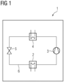
- FIG 1 shows a schematic of a heat pump 1 which has a first heat exchanger 2, a compressor 3, a second heat exchanger 4 and a throttle 5, which are integrated in sequence into a fluid circuit 6 through which a fluid in the form of a coolant is passed.
- energy is extracted from the heat source provided by nature (e.g. air, water or earth), which is transferred to the liquid coolant and evaporates it.
- the coolant is then fed to the compressor 3, which then passes the compressed coolant on to the second heat exchanger 4.
- the coolant is condensed, with the energy extracted from the coolant being transferred to a fluid to be heated, for example heating water, which is heated accordingly.
- the coolant is finally fed to the throttle 5 and relaxed, whereupon it is fed back to the first heat exchanger 2.
- the fluids are guided in a main flow direction 7 through at least one elongated flow channel 8, regardless of whether they are designed as tube, tube bundle, finned tube and plate heat exchangers, wherein the main flow direction 7 corresponds to the longitudinal extent of the flow channel 8.
- the invention is based on the basic idea of providing the at least one flow channel 8 with built-in components and/or design features which impart a swirl in a circumferential direction to the fluid flowing in the main flow direction 7. of the flow channel 8.
- the aim is to increase the intensity of the heat transfer and/or to reduce the required installation space of the heat exchanger 2, 4.
- the Figures 2 and 3 show a first approach according to the invention, in which two swirl bodies 9 are inserted into a flow channel 8 as built-in components.
- the flow channel 8 is a pipe that has a smooth inner surface and a circular cross-section with the diameter D.
- the swirl bodies 9, which are fixed and rigidly inserted into the flow channel 8, each comprise a central center axis 10 extending in the main flow direction 7 and guide vanes 11 extending radially outward from this center axis 10, which impart the swirl in the circumferential direction to the fluid flowing towards the swirl body 9 in the main flow direction 7.
- the guide vanes 11 are designed in an arc shape, the angle ⁇ that the main flow direction 7 encloses with a tangent 12 applied to the downstream edge of a guide vane 12 preferably being 60°.
- This angle ⁇ as well as the number of guide vanes 11, which in this case is eight, can in principle be varied.
- the arrangement of swirl bodies 9 in the flow channel 8 enables, as shown in the Figures 4 and 6 As shown in the reference measurement, the intensity of heat transfer in the flow channel 8 increased by 1.5 to 4 times - depending on the Reynolds number - with a simultaneous increase in hydraulic losses by 2 to 8 times, see Figure 5 . A reduction in the distance L between the two swirl bodies 9 leads to an increase in the intensity of the heat transfer as well as to an increase in the hydraulic losses.
- FIGS 7 to 9 show variants of a flow channel 8 designed according to a second approach according to the invention, which is divided at least in regions into several, in this case three, sub-channels 8a, 8b and 8c extending parallel to one another in the main flow direction 7, between each of which a partition wall 13 extends.
- a first middle sub-channel 8a of the flow channel 8 shown has a square cross-section.
- the other two sub-channels 8b and 8c flanking the middle sub-channel 8a each have a semicircular cross-section.
- the first middle sub-channel 8a is downstream and the second sub-channel 8b and the third sub-channel 8c are each provided upstream with a completely closed baffle plate 14 extending transversely to the main flow direction 7.
- the partition walls 13 are formed with fluid passage openings 15 through which the fluid introduced into the first sub-channel 8a is guided into the second sub-channel 8b and into the third sub-channel 8c while subjecting it to a swirl.
- the distance between the individual fluid passage openings 15 in the direction of the main flow direction 7 increases downstream in the embodiment shown. This geometry is identified below with the index 1.
- the impact plate 14 closing the first middle partial channel 8a is here provided with a central circular through hole 16.
- Figure 10 shows how the fluid passing through the fluid passage openings 15 is subjected to a swirl in the circumferential direction of the flow channel 8, as illustrated by arrows.
- the velocities of the fluid are maximum in the arcuate outer regions of the second and third sub-channels 8b and 8c.
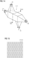
- the Figures 14 to 17 show a third approach according to the invention to increase the intensity of heat transfer.
- the heat exchanger 2, 4 shown has a fluid inlet 18 and a fluid outlet 19 for a first fluid as well as a fluid inlet 20 and a fluid outlet 21 for a second fluid, the fluids being passed through the heat exchanger 2, 4 in countercurrent.
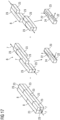
- each flow channel 8 as shown in Figure 17 shown schematically, by a plurality of straight, in the main flow direction extending flow channel sections which are connected to one another via fluid passage openings 22 and which are arranged so as to overlap one another in the main flow direction 7 and offset from one another in directions transverse to the main flow direction 7.
- the individual flow channel sections of a flow channel 8 are positioned in this case such that the flow channel 8 as a whole has a helical shape in the direction of its longitudinal extension.
- Each flow channel 8 through which a hot fluid is passed preferably contacts an adjacent flow channel 8 through which a cold fluid is passed over its entire length, as shown on the left in Figure 17 is shown.
- Two flow channels 8 are thus each "twisted" in a helical manner.
- the flow channel sections are each formed by cuboid-shaped hollow rods 23 with square end faces in the present case, which are each provided with a fluid passage opening 15 at their free ends.
- the fluid passage openings 15 are each slot-shaped and extend in the main flow direction 7, the slot width b preferably corresponding to 0.1 to 0.3 times the length d of an end face of a hollow rod 23, in particular 0.25 times.
- the arrangement of the individual flow channel sections which overlap one another in the main flow direction 7 and are offset in directions transverse to the main flow direction 7, leads to the fluid flowing through the flow channel 8 being subjected to a swirl in the circumferential direction of the flow channel 8, as shown in Figure 17 indicated by the dashed lines 24.
- the flow channels 8 shown can be composed of individual hollow rods that are connected to one another, for example welded or soldered together.
- the matrix-like arrangement can also be manufactured additively, so that the hollow rods are only virtual hollow rods.
- the slot width b of the fluid passage openings of the hollow rods was 0.25 times the length d of one end face of the hollow rods, in a second variant (number “2”) 0.5 times and in a third variant (number "3") 1 times.
- the Figures 18 to 20 show excerpts of the results obtained during the investigations.
- the Figures 21 to 26 show a third inventive approach to increase the intensity of heat transfer in a finned plate heat exchanger.
- the Figures 21, 23 and 25 show three variants of flow channels with largely identical geometry, which are limited by two parallel plates 25 and obliquely positioned ribs 26 and each have a trapezoidal cross-section.
- a rib 26 of a flow channel 8 is provided with fluid passage openings 15 through which the fluid introduced into a flow channel 8 is guided into an adjacent flow channel 8 while subjecting it to a swirl, see Figure 22 .
- the fluid passage openings 15 are on the side from which the fluid is introduced into a flow channel 8, each provided with a cover 27 which is open on the inflow side and which is produced in the present case by slitting and forming the sheet metal forming the rib 26.
- both ribs 27 of a flow channel 8 are provided with corresponding fluid passage openings 15, wherein the covers 27 are selected such that the fluid introduced from one flow channel 8 into the adjacent flow channel 8 is then guided further into the next flow channel 8, see Figure 24 .
- fluid passage openings are provided on both ribs 26 of a flow channel 8, wherein the covers 27 are selected such that the fluid is introduced from two flow channels 8 into a third flow channel 8 arranged between them, see Figure 26 .
- FIG. 30 to 32 compare approaches 1 to 4, which are represented by the numbers “1" to "4".
- the second approach is very promising, as this approach shows the greatest increase in the intensity of heat transfer.
- a key advantage of this second approach, as well as the first and fourth approaches, is that it can be implemented relatively easily in existing heat exchanger designs and can even be retrofitted if necessary.
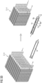
- Figure 33 shows, as an example, on the left a conventional heat exchanger 2, 4, whose flow channels 8 are formed by simple smooth pipes with a circular cross-section, and on the right a heat exchanger 2, 4 modified according to the second approach, in which the construction volume is significantly reduced with a comparable intensity of heat transfer.
- Figure 32 compares the heat transfer intensities of the three approaches at a Reynolds number of 10,000.
- the increase in heat transfer intensity is lower in the third approach than in the second approach.
- the third approach is seen as having the greatest potential for optimization.
- the third approach cannot be implemented with existing heat exchangers. Rather, the technical implementation of the third approach requires the construction of a new heat exchanger 2, 4.
Landscapes
- Engineering & Computer Science (AREA)
- Physics & Mathematics (AREA)
- Thermal Sciences (AREA)
- Mechanical Engineering (AREA)
- General Engineering & Computer Science (AREA)
- Geometry (AREA)
- Heat-Exchange Devices With Radiators And Conduit Assemblies (AREA)
Applications Claiming Priority (3)
| Application Number | Priority Date | Filing Date | Title |
|---|---|---|---|
| DE102021213766.0A DE102021213766A1 (de) | 2021-12-03 | 2021-12-03 | Wärmetauscher und Wärmepumpe mit zumindest einem solchen Wärmetauscher |
| PCT/EP2022/083599 WO2023099444A1 (fr) | 2021-12-03 | 2022-11-29 | Échangeur de chaleur et pompe à chaleur comprenant au moins un tel échangeur de chaleur |
| EP22823366.4A EP4413316A1 (fr) | 2021-12-03 | 2022-11-29 | Échangeur de chaleur et pompe à chaleur comprenant au moins un tel échangeur de chaleur |
Related Parent Applications (2)
| Application Number | Title | Priority Date | Filing Date |
|---|---|---|---|
| EP22823366.4A Division EP4413316A1 (fr) | 2021-12-03 | 2022-11-29 | Échangeur de chaleur et pompe à chaleur comprenant au moins un tel échangeur de chaleur |
| EP22823366.4A Division-Into EP4413316A1 (fr) | 2021-12-03 | 2022-11-29 | Échangeur de chaleur et pompe à chaleur comprenant au moins un tel échangeur de chaleur |
Publications (3)
| Publication Number | Publication Date |
|---|---|
| EP4455593A2 true EP4455593A2 (fr) | 2024-10-30 |
| EP4455593A3 EP4455593A3 (fr) | 2024-12-04 |
| EP4455593B1 EP4455593B1 (fr) | 2026-03-25 |
Family
ID=84535997
Family Applications (3)
| Application Number | Title | Priority Date | Filing Date |
|---|---|---|---|
| EP24184840.7A Pending EP4455594A3 (fr) | 2021-12-03 | 2022-11-29 | Échangeur de chaleur et pompe à chaleur dotée d'au moins un tel échangeur de chaleur |
| EP22823366.4A Withdrawn EP4413316A1 (fr) | 2021-12-03 | 2022-11-29 | Échangeur de chaleur et pompe à chaleur comprenant au moins un tel échangeur de chaleur |
| EP24184839.9A Active EP4455593B1 (fr) | 2021-12-03 | 2022-11-29 | Échangeur de chaleur et pompe à chaleur dotée d'au moins un tel échangeur de chaleur |
Family Applications Before (2)
| Application Number | Title | Priority Date | Filing Date |
|---|---|---|---|
| EP24184840.7A Pending EP4455594A3 (fr) | 2021-12-03 | 2022-11-29 | Échangeur de chaleur et pompe à chaleur dotée d'au moins un tel échangeur de chaleur |
| EP22823366.4A Withdrawn EP4413316A1 (fr) | 2021-12-03 | 2022-11-29 | Échangeur de chaleur et pompe à chaleur comprenant au moins un tel échangeur de chaleur |
Country Status (5)
| Country | Link |
|---|---|
| US (1) | US20250012524A1 (fr) |
| EP (3) | EP4455594A3 (fr) |
| JP (1) | JP7830645B2 (fr) |
| DE (1) | DE102021213766A1 (fr) |
| WO (1) | WO2023099444A1 (fr) |
Families Citing this family (2)
| Publication number | Priority date | Publication date | Assignee | Title |
|---|---|---|---|---|
| CN118070363B (zh) * | 2024-02-20 | 2025-03-18 | 东北电力大学 | 一种用于带有螺旋结构棒束通道的子通道划分方法 |
| KR102825214B1 (ko) * | 2024-11-29 | 2025-06-25 | 유광산 | 음식물 쓰레기 감량기 |
Family Cites Families (31)
| Publication number | Priority date | Publication date | Assignee | Title |
|---|---|---|---|---|
| JPS5257148Y1 (fr) * | 1969-11-25 | 1977-12-24 | ||
| JPS5842827Y2 (ja) * | 1977-11-02 | 1983-09-28 | ダイキン工業株式会社 | 温水ボイラ− |
| JPH0232559B2 (ja) * | 1983-05-06 | 1990-07-20 | Mitsubishi Heavy Ind Ltd | Netsukokanki |
| JPH06123579A (ja) * | 1992-08-24 | 1994-05-06 | Mitsubishi Electric Corp | 熱交換素子 |
| DE19719251C2 (de) * | 1997-05-07 | 2002-09-26 | Valeo Klimatech Gmbh & Co Kg | Verteil-/Sammel-Kasten eines mindestens zweiflutigen Verdampfers einer Kraftfahrzeugklimaanlage |
| JP2001255095A (ja) | 2000-03-15 | 2001-09-21 | Zexel Valeo Climate Control Corp | 熱交換器 |
| KR100496805B1 (ko) * | 2002-11-25 | 2005-06-22 | 최진민 | 보일러용 배플 플레이트장치 |
| US6827138B1 (en) | 2003-08-20 | 2004-12-07 | Abb Lummus Global Inc. | Heat exchanger |
| US7806171B2 (en) * | 2004-11-12 | 2010-10-05 | Carrier Corporation | Parallel flow evaporator with spiral inlet manifold |
| JP2006234267A (ja) | 2005-02-24 | 2006-09-07 | Denso Corp | 沸騰冷却装置 |
| US7363769B2 (en) * | 2005-03-09 | 2008-04-29 | Kelix Heat Transfer Systems, Llc | Electromagnetic signal transmission/reception tower and accompanying base station employing system of coaxial-flow heat exchanging structures installed in well bores to thermally control the environment housing electronic equipment within the base station |
| US7740057B2 (en) * | 2007-02-09 | 2010-06-22 | Xi'an Jiaotong University | Single shell-pass or multiple shell-pass shell-and-tube heat exchanger with helical baffles |
| DE102008052331A1 (de) * | 2007-10-24 | 2009-06-10 | Denso Corp., Kariya-shi | Verdampfereinheit |
| US8661676B2 (en) | 2011-03-29 | 2014-03-04 | Frank G. McNulty | Rotary die forming process and apparatus for fabricating multi-port tubes |
| DE202015103710U1 (de) * | 2015-07-15 | 2015-08-27 | Markus Becker | Gas-Fluid-Gegenstromwärmetauscher |
| US20170089643A1 (en) * | 2015-09-25 | 2017-03-30 | Westinghouse Electric Company, Llc. | Heat Exchanger |
| FR3059404B1 (fr) * | 2016-11-30 | 2019-09-13 | Valeo Systemes Thermiques | Dispositif de distribution d'un fluide refrigerant a l'interieur d'une boite collectrice d'un echangeur thermique pour une installation de conditionnement d'air d'un vehicule |
| DE102017211529A1 (de) | 2017-07-06 | 2019-01-10 | Mahle International Gmbh | Einsatzrohr für den Eintrittskanal eines Plattenwärmetauschers |
| EP3653950A4 (fr) * | 2017-07-13 | 2020-11-25 | Hangzhou Sanhua Research Institute Co., Ltd. | Échangeur de chaleur |
| US10684080B2 (en) * | 2017-07-19 | 2020-06-16 | General Electric Company | Additively manufactured heat exchanger |
| CN108050875B (zh) | 2017-11-14 | 2019-06-07 | 华中科技大学 | 一种适用于换热管的片状涡发生器插入结构及换热管 |
| EP3537086A1 (fr) * | 2018-03-09 | 2019-09-11 | BAE SYSTEMS plc | Échangeur de chaleur |
| DE102018109517A1 (de) | 2018-04-20 | 2019-10-24 | Benteler Automobiltechnik Gmbh | Wärmetauschereinheit |
| CN208187184U (zh) | 2018-05-07 | 2018-12-04 | 辽宁华燃燃气设备有限公司 | 一种高效冲击射流空温式气化装置 |
| JP6993954B2 (ja) | 2018-11-28 | 2022-01-14 | Jfeスチール株式会社 | 熱交換体の製造方法及び熱交換体 |
| CN111288833B (zh) * | 2018-12-06 | 2022-03-15 | 丹佛斯有限公司 | 集流管组件以及换热器 |
| DE102019113205A1 (de) | 2019-05-19 | 2020-11-19 | Modine Manufacturing Co. | Turbulenzerzeugender Einsatz |
| WO2021025151A1 (fr) * | 2019-08-08 | 2021-02-11 | 株式会社デンソー | Échangeur de chaleur |
| EP3982074B1 (fr) * | 2019-10-08 | 2025-01-01 | Hangzhou Sanhua Research Institute Co., Ltd. | Échangeur de chaleur |
| DE102020202835A1 (de) | 2020-03-05 | 2021-09-09 | Hanon Systems | Wärmeübertrager und Verfahren zum Betreiben eines Wärmeübertragers |
| CN115615217A (zh) * | 2021-07-13 | 2023-01-17 | 张宏森 | 涡流热交换装置 |
-
2021
- 2021-12-03 DE DE102021213766.0A patent/DE102021213766A1/de not_active Withdrawn
-
2022
- 2022-11-29 JP JP2024530413A patent/JP7830645B2/ja active Active
- 2022-11-29 EP EP24184840.7A patent/EP4455594A3/fr active Pending
- 2022-11-29 EP EP22823366.4A patent/EP4413316A1/fr not_active Withdrawn
- 2022-11-29 EP EP24184839.9A patent/EP4455593B1/fr active Active
- 2022-11-29 US US18/713,656 patent/US20250012524A1/en active Pending
- 2022-11-29 WO PCT/EP2022/083599 patent/WO2023099444A1/fr not_active Ceased
Also Published As
| Publication number | Publication date |
|---|---|
| EP4455594A3 (fr) | 2024-12-04 |
| JP7830645B2 (ja) | 2026-03-16 |
| WO2023099444A1 (fr) | 2023-06-08 |
| EP4455594A2 (fr) | 2024-10-30 |
| JP2024541457A (ja) | 2024-11-08 |
| EP4455593B1 (fr) | 2026-03-25 |
| DE102021213766A1 (de) | 2023-06-07 |
| US20250012524A1 (en) | 2025-01-09 |
| EP4413316A1 (fr) | 2024-08-14 |
| EP4455593A3 (fr) | 2024-12-04 |
Similar Documents
| Publication | Publication Date | Title |
|---|---|---|
| DE102014004322B4 (de) | Wärmerückgewinnungssystem und Plattenwärmetauscher | |
| DE102005029321A1 (de) | Wärmeübertrager | |
| DE102011013076A1 (de) | Strahltriebwerksvorrichtung mit einem Nebenstromkanal | |
| EP4455593B1 (fr) | Échangeur de chaleur et pompe à chaleur dotée d'au moins un tel échangeur de chaleur | |
| EP3957940B1 (fr) | Module d'échangeur de chaleur à plaque à contre-courant et échangeur de chaleur à plaque à contre-courant | |
| DE102010008175B4 (de) | Wärmeübertrager | |
| DE112022001110T5 (de) | Übergang mit unebener Fläche | |
| DE102020103714A1 (de) | Wärmetauscher | |
| DE19531383A1 (de) | Wärmeübertrager | |
| DE2410292A1 (de) | Waermeaustauscher | |
| EP3203173B1 (fr) | Échangeur thermique de gaz d'échappement | |
| EP1540662B1 (fr) | Distanceur | |
| DE10333463C5 (de) | Rohrbündelwärmetauscher | |
| EP0079090B1 (fr) | Echangeur de chaleur dont le faisceau de tubes est disposé enséries | |
| DE102010044819A1 (de) | Axialturbine und ein Verfahren zum Abführen eines Stroms von einer Axialturbine | |
| DE102009026546B4 (de) | Sonnenkollektor | |
| EP2711658A2 (fr) | Echangeur de chaleur | |
| DE202019103964U1 (de) | Wärmeaustauscher | |
| EP3239641A1 (fr) | Tube plat pour un caloporteur | |
| EP3825636A1 (fr) | Échangeur de chaleur et son procédé de fabrication ou de conception | |
| WO2019141513A1 (fr) | Dispositif de tourbillonnement pour un échangeur de chaleur à plaques et échangeur de chaleur à plaques | |
| DE102019106012A1 (de) | Wärmetauscheranordnung und Wärmetauscher | |
| EP2929272A1 (fr) | Échangeur de chaleur pour machine à combustion interne | |
| DE102019006567B4 (de) | Dampferzeugerflüssigkeitsabscheider und Verfahren zu dessen Herstellung | |
| DE102010001635A1 (de) | Wärmeübertrager |
Legal Events
| Date | Code | Title | Description |
|---|---|---|---|
| STAA | Information on the status of an ep patent application or granted ep patent |
Free format text: STATUS: UNKNOWN |
|
| PUAI | Public reference made under article 153(3) epc to a published international application that has entered the european phase |
Free format text: ORIGINAL CODE: 0009012 |
|
| STAA | Information on the status of an ep patent application or granted ep patent |
Free format text: STATUS: REQUEST FOR EXAMINATION WAS MADE |
|
| REG | Reference to a national code |
Ref country code: DE Ref legal event code: R079 Free format text: PREVIOUS MAIN CLASS: F28D0021000000 Ipc: F28F0001400000 Ref document number: 502022007482 Country of ref document: DE |
|
| 17P | Request for examination filed |
Effective date: 20240627 |
|
| AC | Divisional application: reference to earlier application |
Ref document number: 4413316 Country of ref document: EP Kind code of ref document: P |
|
| AK | Designated contracting states |
Kind code of ref document: A2 Designated state(s): AL AT BE BG CH CY CZ DE DK EE ES FI FR GB GR HR HU IE IS IT LI LT LU LV MC ME MK MT NL NO PL PT RO RS SE SI SK SM TR |
|
| PUAL | Search report despatched |
Free format text: ORIGINAL CODE: 0009013 |
|
| RIC1 | Information provided on ipc code assigned before grant |
Ipc: F28D 21/00 20060101ALI20241008BHEP Ipc: F28F 13/12 20060101ALI20241008BHEP Ipc: F28F 7/02 20060101ALI20241008BHEP Ipc: F28F 3/04 20060101ALI20241008BHEP Ipc: F28F 3/02 20060101ALI20241008BHEP Ipc: F28F 1/40 20060101AFI20241008BHEP |
|
| AK | Designated contracting states |
Kind code of ref document: A3 Designated state(s): AL AT BE BG CH CY CZ DE DK EE ES FI FR GB GR HR HU IE IS IT LI LT LU LV MC ME MK MT NL NO PL PT RO RS SE SI SK SM TR |
|
| RIC1 | Information provided on ipc code assigned before grant |
Ipc: F28D 21/00 20060101ALI20241025BHEP Ipc: F28F 13/12 20060101ALI20241025BHEP Ipc: F28F 7/02 20060101ALI20241025BHEP Ipc: F28F 3/04 20060101ALI20241025BHEP Ipc: F28F 3/02 20060101ALI20241025BHEP Ipc: F28F 1/40 20060101AFI20241025BHEP |
|
| GRAP | Despatch of communication of intention to grant a patent |
Free format text: ORIGINAL CODE: EPIDOSNIGR1 |
|
| STAA | Information on the status of an ep patent application or granted ep patent |
Free format text: STATUS: GRANT OF PATENT IS INTENDED |
|
| INTG | Intention to grant announced |
Effective date: 20251111 |
|
| GRAS | Grant fee paid |
Free format text: ORIGINAL CODE: EPIDOSNIGR3 |
|
| GRAA | (expected) grant |
Free format text: ORIGINAL CODE: 0009210 |
|
| STAA | Information on the status of an ep patent application or granted ep patent |
Free format text: STATUS: THE PATENT HAS BEEN GRANTED |
|
| AC | Divisional application: reference to earlier application |
Ref document number: 4413316 Country of ref document: EP Kind code of ref document: P |
|
| AK | Designated contracting states |
Kind code of ref document: B1 Designated state(s): AL AT BE BG CH CY CZ DE DK EE ES FI FR GB GR HR HU IE IS IT LI LT LU LV MC ME MK MT NL NO PL PT RO RS SE SI SK SM TR |
|
| REG | Reference to a national code |
Ref country code: CH Ref legal event code: F10 Free format text: ST27 STATUS EVENT CODE: U-0-0-F10-F00 (AS PROVIDED BY THE NATIONAL OFFICE) Effective date: 20260325 Ref country code: GB Ref legal event code: FG4D Free format text: NOT ENGLISH |
|
| REG | Reference to a national code |
Ref country code: IE Ref legal event code: FG4D Free format text: LANGUAGE OF EP DOCUMENT: GERMAN |
|
| REG | Reference to a national code |
Ref country code: DE Ref legal event code: R096 Ref document number: 502022007482 Country of ref document: DE |