EP4455604A1 - Arme de chasse ou de sport avec crosse réglable et amovible - Google Patents
Arme de chasse ou de sport avec crosse réglable et amovible Download PDFInfo
- Publication number
- EP4455604A1 EP4455604A1 EP23170118.6A EP23170118A EP4455604A1 EP 4455604 A1 EP4455604 A1 EP 4455604A1 EP 23170118 A EP23170118 A EP 23170118A EP 4455604 A1 EP4455604 A1 EP 4455604A1
- Authority
- EP
- European Patent Office
- Prior art keywords
- buttstock
- hunting
- clamping bolt
- cheek piece
- weapon according
- Prior art date
- Legal status (The legal status is an assumption and is not a legal conclusion. Google has not performed a legal analysis and makes no representation as to the accuracy of the status listed.)
- Withdrawn
Links
Images


Classifications
-
- F—MECHANICAL ENGINEERING; LIGHTING; HEATING; WEAPONS; BLASTING
- F41—WEAPONS
- F41C—SMALLARMS, e.g. PISTOLS, RIFLES; ACCESSORIES THEREFOR
- F41C23/00—Butts; Butt plates; Stocks
- F41C23/14—Adjustable stock or stock parts, i.e. adaptable to personal requirements, e.g. length, pitch, cast or drop
Definitions
- the subject matter of the invention is a hunting or sporting weapon with a height-adjustable and removable cheek piece according to the preamble of patent claim 1.
- Such a cheek piece on a hunting or sporting weapon generally serves as a chin rest on the buttstock of the weapon and optimizes the position of the weapon by supporting the buttstock on the shooter's chin.
- a cheek piece mentioned at the beginning is related to the subject of US 10,088,267 B2 It is a multi-part cheek piece that consists of a total of four parts, whereby these four parts are attached to the buttstock of a weapon with Velcro straps and the height-adjustable part of the cheek piece is designed to be height-adjustable using grid holes and associated fitting bolts.
- Such a cheek piece basically has a U-shaped profile, whereby the two side legs of the U-profile cover the two side surfaces of the buttstock and a central base leg which connects the two side legs of the U-profile to each other and covers the top of the buttstock.
- Two further parts are required for the attachment, namely a shock-absorbing, U-shaped anti-slip cover that directly covers the buttstock and is in turn covered by a U-shaped part that can be strapped onto the buttstock, onto which the height-adjustable cheek piece is attached using the aforementioned grid holes and associated fastening screws.
- This is therefore a large, difficult-to-use, multi-part device that also does not adequately transfer the forces exerted when firing because the tensioning belt attachment of the support part for the height-adjustable cheek piece does not ensure that the cheek piece, which is designed as a chin rest, is securely seated.
- the cheek piece lacks the stability necessary for firing in relation to its position on the buttstock.
- the FR 2 962 530 A1 reveals a height-adjustable cheek piece, which consists of a U-profile, whereby the inside of the two side legs of this profile can be attached to the side surfaces of the buttstock with assigned Velcro fasteners in a height-adjustable manner.
- a stable holder is missing, since The cheek piece is designed as a U-profile and only the two side legs are spring-loaded, so that the force is transmitted to the buttstock solely due to the spring force and the adhesive force of the Velcro fasteners.
- the invention is therefore based on the object of developing a cheek piece designed as a U-profile that is height-adjustable in such a way that it ensures a favorable transmission of the support and torques and is easily adjustable and removable.
- a preferred feature of the invention is that the cheek piece designed as a U-profile is attached only to one side surface, namely in the area of a side leg with an associated detachable attachment to one side of the buttstock.
- the given technical teaching has the advantage that this one-sided fastening is easy to handle and, if necessary, the cheek piece can be removed or attached without having to intervene on the opposite side of the shaft.
- the one-sided fastening of one U-leg of the cheek piece to the side surface of the buttstock is carried out via a spring-loaded clamping bolt which is spring-loaded and slidably arranged in the buttstock and which engages with its head in an associated groove on the inside of the cheek piece and there, due to its spring load, presses one side leg of the U-profile of the cheek piece to the associated side of the buttstock.
- the other side of the cheek piece ie the other side leg of the cheek piece according to the invention, can optionally be supported on the corresponding opposite surface of the buttstock.
- this is not A solution is necessary because if it is preferred that the cheek piece is designed to be rigid, then it is sufficient to attach one side piece to one side and to allow the other side piece to rest on the buttstock or not. In certain positions of the height adjustment, the opposite side piece of the cheek piece can thus protrude freely from the surface of the buttstock.
- the height adjustment is realized in that a first toothed rail is arranged on the fastening side of the buttstock, which has a toothing aligned in the longitudinal direction and which cooperates with an associated, opposite, complementary toothed rail which is arranged on the inside of the side leg of the cheek piece.
- the second toothed rail arranged on the inside of the cheek piece is greater in height than the first toothed rail arranged on the shaft side, in order to achieve the largest possible height adjustment range of the toothed rails which fit together in a form-fitting manner.
- the second toothed rail therefore has a total of more rows of teeth arranged one above the other.
- This simple design therefore assumes that two opposing and complementary toothed rails interlock and that there is a spring-loaded clamping bolt that connects the two toothed rails together in an adjustable and detachable manner.
- the clamping force of the clamping bolt is preferably applied via a compression spring or another spring accumulator.
- the clamping bolt together with its spring is arranged on one side of the buttstock and that a reach through the buttstock is not necessary.
- clamping connection it can be provided in a second embodiment that the clamping bolt holds the buttstock in transverse direction and an associated fastening arrangement is provided on the opposite side of the buttstock.
- the clamping bolt with a threaded bolt reaches through this opposite side of the shaft and a toggle nut can be screwed onto the threaded bolt, which optionally tightens or relaxes the clamping bolt with an associated handle in order to either bring the two mutually complementary toothed rails arranged on the opposite side into or out of engagement.
- the toggle nut can also be omitted and in a further embodiment it is provided that the clamping bolt passes through the buttstock in a transverse direction and a compression spring is provided on the opposite side of the buttstock to compensate for the lack of pre-tensioning of the clamping bolt.
- the clamping bolt has a thread which is arranged at least on the end of the clamping bolt which passes through the buttstock.
- a lock nut is screwed into this bolt-side end, which is pre-tensioned by a compression spring arranged in the buttstock, and the displacement path of the lock nut can be made adjustable.
- the adjustment length of the clamping bolt in the direction of its longitudinal extension corresponds at least to the profile depth of the two interlocking toothed rails in order to bring these into or out of tensioning engagement as required.
- the clamping bolt is also assigned an anti-twisting device, namely via a lead ball which is placed on the outer circumference of the bolt-side end of the clamping bolt and can be fixed with a grub screw.
- a further device is arranged on the fastening side of the buttstock, with which the spring force of the compression spring can be further increased. It is provided that on the clamping or fastening side of the clamping bolt in the area of the lock nut, a wedge surface is arranged in a recess in the buttstock in a transverse direction to the longitudinal axis of the clamping bolt, which interacts with a counter wedge surface of a slide, whereby this slide simultaneously performs a spring-loaded anti-twisting device.
- the slide in turn can be moved in a spring-loaded manner, for example, in a transverse direction to the barrel axis of the weapon and its counter wedge surface rests on an associated wedge surface on the buttstock, which is also aligned in a transverse direction to the barrel axis.
- the slide provided with a wedge surface thus serves on the one hand to unlock or lock the cheek piece adjustment and on the other hand to increase the clamping force of the clamping bolt.
- the cheek piece according to the invention can therefore be adjusted in a variety of ways and with fine adjustment, thus ensuring that the shooter's cheek piece is always positioned exactly so that a target can be aimed at precisely.
- the height-adjustable cheek piece allows the line of sight to be adjusted to the height of the rifle scope and the shooter can always adopt the same shooting position/stance, which means more stability for the shooter.
- the distance between the buttstock and the line of sight is quite large, so that without a cheekpiece the shooter's head no longer rests on the stock, which is uncomfortable and makes an accurate shot impossible.
- This height difference can be compensated for by the height-adjustable cheekpiece according to the invention, which ensures a favorable transmission of the support and torque and is easy to adjust and also removable.
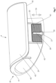
- the hunting or sporting weapon essentially consists of a weapon barrel 1, on which a telescopic sight mount 2 is attached.
- the weapon barrel 1 and a bolt 3 are in the system box 36 of the weapon and the forestock 10 is connected to the front of the system box 36 and the buttstock 5 is connected to the rear.
- the buttstock 5 is closed at the end by a butt cap 6 and there is a trigger 8 at the front of a pistol grip 9.
- FIG. 1 A from Figure 2 , which in Figure 3
- the height-adjustable cheek piece 4 according to the invention is shown, which is designed as a U-profile and which extends with its one side leg over the buttstock 5 according to Figure 3 extends.
- an operating element of the fastening arrangement which essentially consists of a spring-loaded slide 12 which can be moved perpendicularly to the longitudinal axis of the weapon, which can be moved in the area of a lock nut 11 and can be brought into an open position and a cocked position as required.
- FIG. 4 shows further details of the weapon Figure 2 and from section BB and detail A of the Figure 4 , which in Figure 5 in connection with the detail in Figure 6 Further details can be found in the following table.
- the buttstock 5 is designed as a U-profile 39, which essentially consists of a central base leg 41, to which the two side legs 40 and 42 are connected.
- the cheek piece 4 consists of a plastic molded part, preferably of an ABS plastic or a glass fiber reinforced plastic part. In general the cheek piece can be covered with a shock-absorbing surface.
- a support edge 43 on at least one side leg 42 which is either suitable for resting on a support surface 35 of the buttstock 5 or can also be lifted off this support.
- the cheek piece 4 is attached to the buttstock 5 in a height-adjustable manner in the direction of the arrow 26, because on one side of the U-profile 39, namely on the inside of the side leg 40, a first toothed rail 20 is arranged, which has a number of serrated teeth that are aligned in the barrel axis. and which are interrupted in the middle by a T-shaped recess 27, the recess 27 having a passage 30 on the underside for the head of a clamping bolt 18.
- the recess 27 merges into an undercut groove 28, the head 7 of the clamping bolt 18 resting with its head 7 on the inside of the undercut groove 28 in order to bring the toothed rail 20, in which the groove 28 is located, into opposition, ie into clamping engagement (positive engagement) with the shaft-side toothed rail 19.
- stop webs 45 are arranged on the inside of one side leg 40, which represent the end limit of the toothed rail 20, in order to provide a lateral stop limit for the toothed rail 19 interacting with the toothed rail 20.
- the toothed rail 19 attached there forms lateral stop surfaces 46 which interact with the raised stop webs 45 on the inside of the cheek piece 4 in order to achieve additional protection against rotation of the cheek piece 4 on the buttstock 5.
- the protection against rotation is achieved in particular by the mutual engagement of the teeth 21 of the toothed rail 20 and the teeth 22 of the toothed rail 19, whereby a displacement of the teeth relative to one another in the longitudinal direction of the weapon is prevented by the above-mentioned stop surfaces and stop webs.
- the toothed rail 19 on the buttstock side is cast into a recess on the buttstock 5 or is fixed in some other way, for example by a screw connection.
- a recess 31 is provided for the clamping bolt 18 to pass through.
- the clamping bolt 18 thus passes through the buttstock 5 in the transverse direction and engages with its head 7 in the undercut groove 28 of the toothed rail 20 and thus brings the toothed rail 20 arranged on the cheek piece into positive engagement with the toothed rail 19 on the stock side. This situation is due to Figure 6 for further details.
- the fastening side is shown on the right-hand side, where it can be seen that the head 7 of the clamping bolt 18 engages in the associated, undercut groove 28 and brings the two toothed rails 19, 20 into positive, mutual engagement. However, as soon as the clamping bolt is moved to the right in the direction of arrow 24, the two toothed rails 19, 20 come out of engagement and the cheek piece 4 can thus be adjusted in height in the direction of arrow 26.
- the Figure 6 The height adjustment position shown shows that the left side leg 42 can also rest with an inner support edge 43 on an associated, opposite support surface 35 on the system box 36, although this is not necessary for the solution. With a further progressing height adjustment position, the lower support edge 43 also comes out of engagement with the associated support surface 35 and lies freely above it. This requires that the cheek piece 4 is made of a relatively rigid material in order to avoid inadmissible deformation.
- the Figure 6 also shows that the cheek piece 4 according to the invention not only covers the buttstock 5, but also covers the rear part of the system box 36, wherein the cheek piece 4 according to the invention forms a central recess in which the weapon-side bolt guide 37 of the bolt 3 is arranged and slides under the cheek piece 4 in the arrow directions 38 shown.
- the opposite fastening side of the clamping bolt (left side in Figure 6 ) consists of a compression spring 17, which falls into an associated recess on the buttstock 5 and is fixed with its opposite end to the inside of the lock nut 11. This exerts a constant pre-tensioning force in the direction of arrow 24 to the left on the head 7 of the clamping bolt 18.
- the clamping bolt has a thread 23 which is arranged at least on the end of the clamping bolt 18 which passes through the buttstock.
- a lead ball 15 is provided to prevent the clamping bolt 18 from twisting. This ball is pressed onto the outer circumference of the thread of the clamping bolt 18 using a grub screw 44 in order to make it twist-proof.
- the lead ball 15 is fixed in a transverse hole in the lock nut 11 and is secured with the grub screw 44.
- the thread for the grub screw 44 is also arranged in the transverse bore of the lock nut 11.
- the above-mentioned fixing means serve, alone or in combination, to enable the clamping bolt 18 to be moved to the right in the direction of arrow 24 when pressure is applied to the lock nut 11, without the setting of the clamping bolt 18 being able to change.
- the lock nut 11 is equipped with a special device which provides an additional reinforcement of the clamping force which acts from the head 7 on the two toothed rails 19, 20 and accordingly on the gears 21, 22 assigned to the two toothed rails.
- the clamping force on the clamping bolt 18 can be increased by a spring-loaded slider 12 in the lock nut 11.
- the slider - according to Figure 6 - can be moved in the direction of the arrow 25 in a corresponding longitudinally aligned slot in the lock nut 11 under spring load.
- the slide 12 has a lower, inner counter wedge surface 34 which interacts with a corresponding, complementary wedge surface 33 in the buttstock 5.
- the spring-loaded displacement of the slide 12, the spring load being generated by a compression spring 13, causes the two wedge surfaces 33, 34 to be moved against one another and thus exert an additional displacement force on the clamping bolt 18.
- the lock nut 11 can also have an additional anti-twist device in the form of a pin so that it cannot twist in a recess 14 in the buttstock 5.
- the spring-loaded, movable slide 12 can be moved in a spring-loaded manner in a T-slot 48 in the lock nut 11.
- the compression spring 13 is located below the slide 12 and is supported on the lock nut 11 in such a way that a spring force is generated when the slide is moved upwards in the direction of arrow 25.
- the T-slot 48 is limited at the bottom by lateral guide surfaces 49, which represent the sliding guide for the slider 12 in the lock nut 11.
- the support edge 43 can have an inwardly directed leg which is supported on the associated support surface 35 on the buttstock 5. It is intended that support can take place not only on the buttstock 5, but also on the system box 36.
- the height adjustment position can be moved upwards in the direction of the arrow 26 so far that the support edge 43 of the cheek piece 4 comes out of engagement with the opposite support surface 35 on the buttstock or the system box.
- the novel height-adjustable cheek piece 4 which has only a one-sided clamping attachment, ensures a particularly reliable height-adjustable attachment of the cheek piece to the buttstock 5 or also to the rear part of the system box 36 covered by the cheek piece 4.
- the one-sided fastening on one side of the buttstock 5 and the opposite operation of this fastening on the opposite side of the buttstock result in the advantage of clear operation with one hand and in particular it is ensured that on the side where the longer side leg 40 of the cheek piece 4 is present and the shooter's cheek piece rests, there are no protruding parts whatsoever because this is the cocking side and there are completely smooth surfaces on the outside.
- a removal movement of the cheek piece according to the invention is described in more detail below.
- the slide 12 is first moved against the force of the compression spring 13 into its raised position and at the same time a pressure is generated on the lock nut 11 in the direction of the longitudinal extension of the clamping bolt 18, whereby the head 7 of the clamping bolt inevitably lifts the toothed rail 20 from the cheek-side toothed rail 19 and disengages it.
- the cheek piece 4 can be raised or lowered in any position of the teeth 21, 22 and only when the lock nut 11 is released under the force of the compression spring 17 is the clamping bolt returned to its original clamping position and the two complementary teeth 21, 22 come into fluid engagement again. In this way, a particularly reliable and easy height adjustment of the cheek piece 4 is ensured. If the cheek piece 4 is to be removed completely, the cheek piece is pulled upwards while the lock nut 11 is pressed until the head 7 of the clamping bolt 18 comes into the area of the passage 30 of the recess 27 of the cheek-side toothed rail 20 and the toothed rail 20 can be removed from the weapon together with the cheek piece.
Landscapes
- Engineering & Computer Science (AREA)
- General Engineering & Computer Science (AREA)
- Clamps And Clips (AREA)
Priority Applications (1)
| Application Number | Priority Date | Filing Date | Title |
|---|---|---|---|
| EP23170118.6A EP4455604A1 (fr) | 2023-04-26 | 2023-04-26 | Arme de chasse ou de sport avec crosse réglable et amovible |
Applications Claiming Priority (1)
| Application Number | Priority Date | Filing Date | Title |
|---|---|---|---|
| EP23170118.6A EP4455604A1 (fr) | 2023-04-26 | 2023-04-26 | Arme de chasse ou de sport avec crosse réglable et amovible |
Publications (1)
| Publication Number | Publication Date |
|---|---|
| EP4455604A1 true EP4455604A1 (fr) | 2024-10-30 |
Family
ID=86226657
Family Applications (1)
| Application Number | Title | Priority Date | Filing Date |
|---|---|---|---|
| EP23170118.6A Withdrawn EP4455604A1 (fr) | 2023-04-26 | 2023-04-26 | Arme de chasse ou de sport avec crosse réglable et amovible |
Country Status (1)
| Country | Link |
|---|---|
| EP (1) | EP4455604A1 (fr) |
Citations (7)
| Publication number | Priority date | Publication date | Assignee | Title |
|---|---|---|---|---|
| DE3401299A1 (de) | 1984-01-16 | 1985-07-25 | J.G. Anschütz GmbH, 7900 Ulm | Schusswaffe |
| US20110016764A1 (en) | 2009-07-21 | 2011-01-27 | Steven Cales | Rifle stock cheek rest |
| FR2962530A1 (fr) | 2010-07-07 | 2012-01-13 | Emmanuel Amoreau | Arme a feu munie d'appuie-joue sureleve amovible |
| US20140196343A1 (en) * | 2013-01-11 | 2014-07-17 | Sig Sauer, Inc. | Adjustable cheek rest |
| WO2016115209A1 (fr) * | 2015-01-13 | 2016-07-21 | Sturm, Ruger & Company, Inc. | Crosse réglable pour arme à feu |
| US10088267B2 (en) | 2013-03-20 | 2018-10-02 | Rick Bradford SLATER | Adjustable cheek rest |
| US20210018296A1 (en) * | 2019-07-16 | 2021-01-21 | Sagi Faifer | Variably adjustable stock for a gun and apparatus and method for adjustment of same |
-
2023
- 2023-04-26 EP EP23170118.6A patent/EP4455604A1/fr not_active Withdrawn
Patent Citations (7)
| Publication number | Priority date | Publication date | Assignee | Title |
|---|---|---|---|---|
| DE3401299A1 (de) | 1984-01-16 | 1985-07-25 | J.G. Anschütz GmbH, 7900 Ulm | Schusswaffe |
| US20110016764A1 (en) | 2009-07-21 | 2011-01-27 | Steven Cales | Rifle stock cheek rest |
| FR2962530A1 (fr) | 2010-07-07 | 2012-01-13 | Emmanuel Amoreau | Arme a feu munie d'appuie-joue sureleve amovible |
| US20140196343A1 (en) * | 2013-01-11 | 2014-07-17 | Sig Sauer, Inc. | Adjustable cheek rest |
| US10088267B2 (en) | 2013-03-20 | 2018-10-02 | Rick Bradford SLATER | Adjustable cheek rest |
| WO2016115209A1 (fr) * | 2015-01-13 | 2016-07-21 | Sturm, Ruger & Company, Inc. | Crosse réglable pour arme à feu |
| US20210018296A1 (en) * | 2019-07-16 | 2021-01-21 | Sagi Faifer | Variably adjustable stock for a gun and apparatus and method for adjustment of same |
Similar Documents
| Publication | Publication Date | Title |
|---|---|---|
| EP1601925B1 (fr) | Arme a feu de poing et guarde destinee a celle-ci | |
| DE102011013575A1 (de) | Vorrichtung zum Befestigen eines Zusatzgerätes an einer Schusswaffe | |
| WO2009097873A1 (fr) | Poignée auxiliaire pour une arme à feu portative | |
| AT506542A1 (de) | Verriegelbare ausstossvorrichtung für ein in einem möbel bewegbar gelagertes möbelteil | |
| DE202015101485U1 (de) | Abzugseinrichtung einer Handfeuerwaffe | |
| EP2956732A1 (fr) | Système universel de montage de lunettes de visée pour armes à feu de poing | |
| DE4005369C9 (de) | Schließeinrichtung an einer Fahrzeugtür | |
| EP4455604A1 (fr) | Arme de chasse ou de sport avec crosse réglable et amovible | |
| DE102017121641B4 (de) | Riemenspanner für Längsförderer | |
| EP3973244B1 (fr) | Boîtier supérieur pour une arme à feu | |
| DE4403927C2 (de) | Befestigungsvorrichtung für Bretter oder Regalbretter | |
| DE102006059914A1 (de) | Schaft einer Schusswaffe sowie Schaftkappe und Wangenkappe für einen solchen Schaft | |
| AT520202B1 (de) | Schaft für eine Handfeuerwaffe | |
| EP2570762B1 (fr) | Arme de chasse et de sport avec fixation pour une lunette de visée | |
| DE19538006C1 (de) | Justiereinrichtung für eine zumindest zweiläufige Waffe | |
| EP3929523B1 (fr) | Dispositif de logement d'un agencement cible | |
| DE102006024508B4 (de) | Halterung für Zusatzgeräte an Feuerwaffen | |
| CH714375B1 (de) | Gewehr mit Dämpfungsplatte. | |
| DE3128848A1 (de) | Schusswaffe, insbesondere langwaffe | |
| EP4296604B1 (fr) | Plaque de couche réglable en longueur à amortissement de recul intégrée pour une arme, en particulier une arme de chasse ou de sport | |
| DE19532154C2 (de) | Schießvorrichtung zur Aufnahme einer Faustfeuerwaffe | |
| EP3599928B1 (fr) | Boucle de ceinture pour une ceinture abdominale | |
| DE19856248A1 (de) | Feuerwaffen und Zubehör | |
| EP4703671A1 (fr) | Arme de chasse ou de sport avec crosse de serrage et guidage coulissant ajustables et ajustables et amovibles | |
| EP1471325A1 (fr) | Garde-main en matière plastique |
Legal Events
| Date | Code | Title | Description |
|---|---|---|---|
| PUAI | Public reference made under article 153(3) epc to a published international application that has entered the european phase |
Free format text: ORIGINAL CODE: 0009012 |
|
| STAA | Information on the status of an ep patent application or granted ep patent |
Free format text: STATUS: THE APPLICATION HAS BEEN PUBLISHED |
|
| AK | Designated contracting states |
Kind code of ref document: A1 Designated state(s): AL AT BE BG CH CY CZ DE DK EE ES FI FR GB GR HR HU IE IS IT LI LT LU LV MC ME MK MT NL NO PL PT RO RS SE SI SK SM TR |
|
| STAA | Information on the status of an ep patent application or granted ep patent |
Free format text: STATUS: THE APPLICATION IS DEEMED TO BE WITHDRAWN |
|
| 18D | Application deemed to be withdrawn |
Effective date: 20250501 |