EP4455606A2 - Projectile - Google Patents
Projectile Download PDFInfo
- Publication number
- EP4455606A2 EP4455606A2 EP24191821.8A EP24191821A EP4455606A2 EP 4455606 A2 EP4455606 A2 EP 4455606A2 EP 24191821 A EP24191821 A EP 24191821A EP 4455606 A2 EP4455606 A2 EP 4455606A2
- Authority
- EP
- European Patent Office
- Prior art keywords
- projectile
- section
- prongs
- end section
- view
- Prior art date
- Legal status (The legal status is an assumption and is not a legal conclusion. Google has not performed a legal analysis and makes no representation as to the accuracy of the status listed.)
- Granted
Links
Images
















Classifications
-
- F—MECHANICAL ENGINEERING; LIGHTING; HEATING; WEAPONS; BLASTING
- F42—AMMUNITION; BLASTING
- F42B—EXPLOSIVE CHARGES, e.g. FOR BLASTING, FIREWORKS, AMMUNITION
- F42B12/00—Projectiles, missiles or mines characterised by the warhead, the intended effect, or the material
- F42B12/02—Projectiles, missiles or mines characterised by the warhead, the intended effect, or the material characterised by the warhead or the intended effect
- F42B12/34—Projectiles, missiles or mines characterised by the warhead, the intended effect, or the material characterised by the warhead or the intended effect expanding before or on impact, i.e. of dumdum or mushroom type
-
- B—PERFORMING OPERATIONS; TRANSPORTING
- B21—MECHANICAL METAL-WORKING WITHOUT ESSENTIALLY REMOVING MATERIAL; PUNCHING METAL
- B21K—MAKING FORGED OR PRESSED METAL PRODUCTS, e.g. HORSE-SHOES, RIVETS, BOLTS OR WHEELS
- B21K1/00—Making machine elements
- B21K1/02—Making machine elements balls, rolls, or rollers, e.g. for bearings
- B21K1/025—Making machine elements balls, rolls, or rollers, e.g. for bearings of bullets
-
- F—MECHANICAL ENGINEERING; LIGHTING; HEATING; WEAPONS; BLASTING
- F42—AMMUNITION; BLASTING
- F42B—EXPLOSIVE CHARGES, e.g. FOR BLASTING, FIREWORKS, AMMUNITION
- F42B10/00—Means for influencing, e.g. improving, the aerodynamic properties of projectiles or missiles; Arrangements on projectiles or missiles for stabilising, steering, range-reducing, range-increasing or fall-retarding
- F42B10/32—Range-reducing or range-increasing arrangements; Fall-retarding means
- F42B10/38—Range-increasing arrangements
- F42B10/42—Streamlined projectiles
-
- F—MECHANICAL ENGINEERING; LIGHTING; HEATING; WEAPONS; BLASTING
- F42—AMMUNITION; BLASTING
- F42B—EXPLOSIVE CHARGES, e.g. FOR BLASTING, FIREWORKS, AMMUNITION
- F42B12/00—Projectiles, missiles or mines characterised by the warhead, the intended effect, or the material
- F42B12/72—Projectiles, missiles or mines characterised by the warhead, the intended effect, or the material characterised by the material
- F42B12/74—Projectiles, missiles or mines characterised by the warhead, the intended effect, or the material characterised by the material of the core or solid body
-
- F—MECHANICAL ENGINEERING; LIGHTING; HEATING; WEAPONS; BLASTING
- F42—AMMUNITION; BLASTING
- F42B—EXPLOSIVE CHARGES, e.g. FOR BLASTING, FIREWORKS, AMMUNITION
- F42B33/00—Manufacture of ammunition; Dismantling of ammunition; Apparatus therefor
-
- F—MECHANICAL ENGINEERING; LIGHTING; HEATING; WEAPONS; BLASTING
- F42—AMMUNITION; BLASTING
- F42B—EXPLOSIVE CHARGES, e.g. FOR BLASTING, FIREWORKS, AMMUNITION
- F42B8/00—Practice or training ammunition
- F42B8/12—Projectiles or missiles
- F42B8/14—Projectiles or missiles disintegrating in flight or upon impact
Definitions
- the invention relates to an intermediate for producing projectiles, in particular deformation projectiles or partially fragmenting projectiles, wherein the finished projectile in particular has a particularly unfilled cavity, in particular in the area of the ogive, which is delimited by an ogive wall of the projectile.
- a ductile, in particular lead-free, material such as copper, a copper alloy, brass or the like can be used for the intermediate.
- the invention further relates to the projectile, in particular of the deformation projectile itself.
- the invention relates to a projectile deformed in particular under idealized test conditions, which after a shot hits a particularly uncovered gelatinous mass and is caught in order to inspect and assess ideal deformation behavior.
- the invention further relates to a tool for producing the intermediate and in particular the projectile.
- the invention also relates to a method for producing the intermediate and optionally subsequently the projectile of the deformation projectile.
- the invention relates to a projectile deformed by use after it has hit the gelatinous mass according to known test methods, is caught there and can be assessed.
- a projectile or projectile head using a so-called intermediate or intermediate product, whereby a cold forming process such as deep drawing is used.
- An intermediate for producing a projectile of a projectile, in particular a deformation projectile or partial fragmentation projectile, similar to the generic object is known from US 5,259,320 known. Accordingly, a copper blank is inserted into a cylindrical die and cold-formed using a mandrel or punch, whereby the mandrel penetrates the blank in the axial longitudinal direction in order to provide it with a recess starting from the ogive side to be formed. The ductile material is deflected by means of the die and the mandrel, whereby the desired intermediate for the projectile is formed.
- the mandrel can have a pyramidal shape with four flat, inclined flank surfaces that lead to straight separating edges.
- a corresponding negative profile is pressed into the blank.
- the mandrel can have a conical structure in order to form a corresponding negative cone shape in the blank.
- the manufactured intermediate is provided with a closed, externally cylindrical wall and a centered press recess introduced into the press end section.
- the wall runs completely and without breakage in the circumferential direction around the press recess.
- the wall is formed into an ogive tip to produce the final product of the projectile. This creates a completely closed inner surface contact in the end area of the jacket, which provides a closed cavity within the ogive of the projectile.
- the cavity is completely closed in the circumferential direction by the wall forming the ogive.
- an intermediate for the manufacture of a projectile, in particular a deformation projectile, consisting of a ductile, cylindrical base body.
- the base body can be made of a homogeneous metal material, such as copper, copper alloy, brass, lead, etc.
- the base body is preferably made of a lead-free material.
- the base body can be made of a cut blank, which can in particular be formed from a cut ductile metal material.
- the base body is cold formed by means of pressing, in particular deep drawing, and in particular using a punch-die arrangement.
- the base body or blank to be formed into the intermediate forms, as an intermediate, a cylindrical, solid base end section, which preferably comprises a substantially flat end face facing the projectile casing.
- the intermediate comprises a press end section, which is diametrically opposite in the axial direction of the projectile, the press end section being designed with a central press depression introduced by the pressing process and a jacket or wall delimiting the press depression to form an ogivoid-shaped tip of the projectile.
- the intermediate can be provided with a jacket made of a metal material or another suitable material that completely covers the base body or core in the area of the rear, the guide section (shoe) and up to the bow of the projectile intermediate, with the bow-side front side in particular remaining open so that access to the base body is possible.
- the jacket in particular surrounds the base body almost completely in the circumferential direction. Only on the bow front side is no jacket material provided for the introduction of a forming tool.
- the jacket can be made of a different material or the same material as the base body.
- a homogeneous metal material such as copper, copper alloy, brass, lead, etc. can be used for the jacket.
- the jacket is preferably made of a lead-free material.
- the base body forms the core of the intermediate of the projectile to be formed from it.
- the core is surrounded by the jacket, in particular completely surrounded when the projectile is finished from the intermediate.
- the base body can preferably be in two parts, with a bow-side section being unaffected by the slitting, while a rear-side area is reshaped by the slitting.
- the wall to be formed into an ogive in the subsequent forming process of the intermediate is designed with at least two slots extending in the axial direction of the intermediate, resulting in a corresponding number of prongs or wall sections separated in the circumferential direction by the slots.
- the slots or through slots completely penetrate the wall surrounding the cavity or the press recess radially, so that the intermediate according to the invention and also the projectile have free radial access to the cavity via the radial through slots. Only when the slotted wall is formed into an ogive section is the cavity at least partially closed in the circumferential direction due to the side edges of the structurally separated prongs formed by the slots touching or lying closely together to form a gap.
- the at least two slots in particular exactly three or four slots (consequently exactly three or four prongs), are arranged in the circumferential direction at the same circumferential distance arranged relative to one another in order to form a slot/tine arrangement that is point-symmetrical to the axial direction of the intermediate.
- the at least two slots separate the respective at least two tines that form the structure of the wall and are intended to delimit a cavity in the circumferential direction of the intermediate, with two adjacent tines of the wall being assigned to one slot in particular.
- the tines extend from a slot bottom, which forms the end of the slot on the base end section side, in the axial direction to a tine end or tip, which tine ends form the axial end of the wall and thus of the intermediate.
- the at least two slots extend by more than 10% of an axial total longitudinal extent of the intermediate from the wall end in the direction of the base end section.
- the total length of the extension of the slot to be considered here should be the axial dimension from the wall end to the slot bottom at the transition between two adjacent tines.
- the respective prong grows in the axial direction towards the prong end from the base end section, which geometrically ends through the slot in the axial direction, wherein the circumferential width of each prong of the at least two prongs preferably decreases continuously and evenly in the axial direction towards the prong end, whereby in particular the circumferential width of the slot lying between two prongs increases in the axial direction towards the wall end, in particular gradually and/or continuously.
- the slot can be continuous or have a slotted base to close off the cavity or the press recess radially in the circumferential direction, wherein the slotted base serves radially on the outside to complete a continuous, step-free, in particular cylindrical, outside of the intermediate.
- the slot can form a channel structure extending in the longitudinal direction of the projectile, which is open to the interior of the cavity.
- a depth of the slot from the cavity to the slotted base can vary, in particular increasing continuously in the longitudinal direction towards the rear of the intermediate.
- the slit is completely incorporated in the base body and, if applicable, in the casing surrounding the base body.
- the slotted bottom is formed to be uniform in the circumferential direction on the cavity side, in particular of the same width, with the slotted bottom extending continuously towards the longitudinal axis of the intermediate into the common cavity bottom of the inner cavity.
- the inner sides of the tines formed by the slots also open into the hollow floor.
- the slit and thus the desired inner hollow profile is shaped for the intermediate in such a way that when the intermediate is formed into the projectile, the prongs introduced through the slit serve as gripping arms and/or a separate tip, for example made of plastic, is inserted and attached, in particular pressed, to form the nose of the projectile.
- a separate tip for example made of plastic
- this can be used to achieve a clamping of the tip mentioned.
- the intermediate shape according to the invention is accompanied by an extremely easy to implement but uniform deformation of the blank without the formation of deep-drawing waves.
- the mold forming the intermediate shape according to the invention provides an escape space for material of the intermediate to be formed later, in particular material of the prongs.
- the undesirable wave formation is largely avoided.
- a projectile with the intermediate according to the invention is provided which is produced exclusively by a cold forming process, in particular without having to use machining processes.
- the cold-formed intermediate/projectile also achieves the desired partial fragmentation deformation behavior without the projectile splintering when it hits the gelatinous mass according to the standardized test procedures.
- the at least two slots extend by more than 20%, 25%, 30%, 35%, 40%, 45% or 50% of the total axial extent of the ogive to be formed later in the area of the slotted press end section provided with a press recess.
- the at least two slots extend over the entire axial longitudinal extent of the press end section, so that the ogive to be formed is completely realized by the wall formed with at least two, exactly three or four, slots.
- the prongs or wall sections elongated by the corresponding length of the slots form the ogive wall for delimiting the cavity of the projectile, which is designed to be open at the ogive tip with an opening, the clear cross section of which according to the invention is less than 20%, 15%, 10% or 5% of the caliber cross-section of the projectile.
- the at least two slots define a circumferential width to be measured in the circumferential direction, particularly arising from the base end section at the level of the slot bottom.
- the circumferential width of the at least two slots increases in particular continuously from the slot bottom to the casing tip.
- the slope of the flank edge of the tine delimiting the slot is essentially constant in the course from the slot bottom to the wall tip, in particular in a main region between the slot bottom to the wall end, wherein the slot bottom is rounded, and the wall tip also has a rounding with a changed slope.
- the at least two slots can open continuously from the slot bottom in the axial direction, wherein the slot opening is maximum in particular at the wall tip.
- the at least two prongs are shaped and dimensioned substantially identically in order to form a symmetrical, in particular point-symmetrical, structure of the intermediate at least in the region of the pressing end section or completely, which will largely form the ogive of the projectile.
- the at least two prongs grow from the slot bottom and the pressing depression arch in the axial direction.
- the prongs can also be shaped as prongs, whereby they can not necessarily, but preferably, run into a pointed end, which is preferably rounded, whereby the prong end can extend bluntly in the circumferential direction.
- the design of the respective prong is decisive.
- an inner surface of the respective prong facing the pressing recess is convex in the circumferential direction and/or in the axial direction.
- a material thickness of the prong increasing towards the middle of the circumferential direction is provided, wherein in particular the outward-facing outer surface of the prong is cylindrical and in particular already substantially corresponds to the caliber of the projectile.
- Two flank surfaces on the inside of the prong which are designed in particular axially symmetrical to the axial center axis of the prongs, extend from the edge of the prong delimiting the slot and extending in the axial direction to its Middle.
- the two flank surfaces that are adjacent to one another are at an angle to one another, with the apex of the flank surfaces essentially corresponding to the center axis of the tine, along which the tine is the strongest and has the greatest material thickness.
- the middle region of the tine is designed with a material extension maximum that extends as an edge from the tine tip to the base end section.
- an inner surface that is convex in the circumferential direction has an edge-like projection that projects into the press recess essentially halfway along the circumferential width of the tine and that preferably extends in a straight line from the axial height of the slot base to the tine tip.
- the flat, convex or concave flank surface of the tine can slope down from the edge-like projection to a side edge of the tine that delimits the respective adjacent slot, as far as the material thickness of the tine is concerned.
- the edge- or web-like projection is rounded towards both inner flank surfaces.
- the convex inner surface is preferably designed without projections.
- the outer surfaces of the tine are cylindrical, in particular in accordance with the die used for the method.
- the lateral boundary edge of the tine represents the end of the cylindrical outer side of the tine, at which there is a profile break towards the inner surface of the tine, which inner surface has the convex shape in the circumferential direction or in the axial direction.
- a recess such as a groove or a slot, can be formed, which in particular also extends in a straight line from the tine tip to the axial height of the slot bottom, which interrupts the convex design of the flank inner surface.
- the at least two prongs define a wall thickness in the circumferential transverse slot view.
- the wall thickness of the prong preferably decreases from a side edge delimiting the respective adjacent slot (Transition between the cylindrical outer surface and the inner side of the tine) at a certain axial height and in particular along the entire axial extension towards a maximum wall thickness. From the maximum wall thickness, the wall thickness can decrease again towards the opposite side edge, in particular continuously.
- the maximum wall thickness is formed in the circumferential direction essentially in the middle of the tine.
- a reduction in the wall thickness in the form of a recess can be provided, which adjoins an increase in wall thickness.
- the respective tine comprises two wall thickness maxima, which are delimited by the recess. From the respective maximum wall thickness, the wall thickness decreases towards the adjacent side edge, which delimits the slot.
- the maximum wall thickness extends over a region of the axial extension of the tine, in particular in the axial middle region of the tine.
- the wall thickness maximum can extend substantially from the tine end up to the axial height in the region of the slot bottom and beyond to the press recess bottom.
- the press depression extends over more than 50%, in particular between 50% and 80%, preferably more than 60%, preferably between 60% and 80%, in particular in the range of 75%, of the total axial extent of the intermediate or projectile.
- the press depression defines a depression base, in the center of which the slot bottoms of the at least two slots extend radially and optionally axially to the cylindrical outer side.
- the base end section without a press depression consists of the solid material of the blank and is limited in the axial direction by the press depression base and the slot bottoms extending away from it.
- the press end section of the intermediate extends from this boundary, in which the casing is slotted.
- the projection formed on the inner surface of the respective tine preferably extends in the axial direction beyond the axial height of the slot base, in particular essentially completely up to the press recess base.
- the projection preferably merges continuously into the recess base without forming a profile projection. The same applies to the recess that may be formed instead of a projection in the area of the inner surface of the respective tine.
- a depression base which represents the dead-end region of the press depression, is spherically shaped.
- the depression base can also be flat, with a maximum width of 10 mm or a few millimeters.
- the depression base can extend radially in such a way that it merges into a slot base, in particular all slot bases of the at least two slots, in particular continuously.
- the slot bases can be flat as strips or rounded like a groove and open into a corresponding shape of the central depression base.
- the outside of at least two prongs is cylindrical, while the inner surface curves convexly towards a prong tip, whereby the inclination of the curve can gradually increase compared to the vertical.
- exactly three prongs are provided for the wall of the press end section, which are arranged at an angle of 120° at the same circumferential distance from one another.
- exactly four prongs can be provided, the central axes of which are arranged essentially at a 90° circumferential distance from one another.
- the respective prongs have an identical or similar shape and an identical cross-section, in particular in the entire axial course from the recess base to the prong tip.
- exactly two prongs are provided, with the two slots that separate the prongs on both sides narrowing in a radial direction towards a center (the longitudinal axis of the intermediate) and widening radially outwards from the center.
- the exactly two prongs are identically shaped and lie axially symmetrically opposite one another.
- the deformation control during impact is achieved by the special design of the at least two prongs in conjunction with the pressing depression and therefore the at least two slots.
- the convex area of the inside of the prong causes a strengthening in the area of the weakening of the pressing end section of the intermediate caused by the pressing depression.
- the slot which delimits two prongs and decreases from the pointed end to the slot bottom, strengthens the prong foot that merges into the base end section.
- the dimensional stability exists in the entire axial course and in the cross section along the axial course of the prong from the depression bottom to the prong end.
- the punch which is to be used to profile the press end section for the intermediate is designed like a Phillips screwdriver, the diameter of which is larger than the diameter of the intermediate.
- Two-prong, three-prong, four-prong or multi-prong screwdrivers can be used. It is the prongs of the blade of the Phillips screwdriver which create the slots in the blank for forming the intermediate, with the central section of the screwdriver forming press recesses.
- the invention further relates to a projectile for a deformation projectile, which is made from a ductile blank that is first cold-formed into the intermediate.
- the projectile is finally produced by a forming process.
- the projectile is to be produced using the intermediate according to the invention.
- the invention also relates to a projectile, in particular a deformation projectile or a partial fragmentation projectile, which comprises a cylindrical, solid base end section and an ogive section integrally connected to the base end section with a wall for circumferentially enclosing a particularly unfilled cavity and an opening centered at a tip of the ogive section with a clear opening cross-section of less than 20%, 15%, 13%, 10%, 8% or 5% of the caliber cross-section of the projectile defined by the base end section.
- a projectile in particular a deformation projectile or a partial fragmentation projectile, which comprises a cylindrical, solid base end section and an ogive section integrally connected to the base end section with a wall for circumferentially enclosing a particularly unfilled cavity and an opening centered at a tip of the ogive section with a clear opening cross-section of less than 20%, 15%, 13%, 10%, 8% or 5% of the caliber cross-section of the projectile defined by the base end section
- the maximum dimension which for example in the case of a Y-shaped opening, a star-shaped opening, an I-shaped opening, the longest linear dimension is to be measured for example from a star leg to the opposite boundary wall, is smaller than 17%, 15%, 13% or 10% of a diameter of the base end section.
- an ogive tip opening of such dimensions is sufficient to break through harder materials, such as elastic materials or textile fabrics, without causing the ogive tip opening to become coated or blocked.
- the gelatinous material can then easily penetrate into the empty cavity of the ogive section in order to build up the hydraulic pressure which causes the desired partial deformation of the projectile.
- the invention relates to a projectile, in particular a deformation projectile.
- the projectile comprises a cylindrical solid base end section, which preferably comprises a flat front surface, which in a further embodiment can have a central depression or indentation which is axially aligned in the direction of the ogive tip.
- the base end section is used to be inserted into a casing of the projectile or ammunition.
- the projectile has a press end section which is diametrically opposite the base end section in the axial direction and which essentially corresponds to that of the intermediate.
- the press section has a central press depression introduced by pressing and a wall which delimits the press depression and which is formed into an ogive-shaped tip.
- the wall of the projectile has at least two wall sections. It is clear that the above-mentioned prongs or wall sections form the ogive of the projectile as soon as the prongs are transformed from their cylindrical orientation on the outer surface to the pointed arch-shaped ogive.
- the ogive should preferably be tangentially oriented.
- adjacent wall sections are bent in the circumferential direction in such a way that they touch each other at least in sections, so that in the area of contact of the wall sections, a cavity formed by the press depression, in particular during the formation of the intermediate, is enclosed in the circumferential direction (ie in the area of section-wise contact of the side edges of the ogive sections).
- the closure is complete in the circumferential direction as soon as there is contact of the side edges.
- the side edges do not have to touch completely, but, as stated above, the contact can be in sections.
- the cavity which is to be limited by the wall sections in the circumferential direction, is not completely open, but has at least three openings, a central opening at the ogive tip, as already stated above, and at least two side openings in the area of the slotted bottoms, which are set when the intermediate is produced.
- the number of side openings depends on the number of slotted bottoms.
- the side openings are preferably identically shaped in their clear cross-section.
- the cross-section of the side openings can have a substantially triangular, heart or spade shape and can extend over a small area up to an area of more than 30% of the axial extent of the cavity.
- the projectile is manufactured starting from the intermediate according to the invention.
- the finished intermediate is then cold bent to form the respective ogive section. For this purpose, it can be inserted into a corresponding die.
- a contact length of adjacent ogive sections at their side edges is more than 20%, 30%, 40%, 50%, 60%, 70%, 80% or 90% of a total length of the side edges of the respective ogive sections.
- the side edges are measured from the tip of the respective ogive section to a slot bottom.
- there is contact of the side edges along the entire length of the side edges so that the touching ogive sections completely close the cavity.
- a completely complete closure is difficult to achieve in terms of manufacturing technology, so that it can be assumed that a small opening of less than 2 mm or 1 mm remains in the zone of the slot bottom, which does not affect the aerodynamics and the impact deformation.
- This side opening which results from the slot bottom in the intermediate and the subsequent deformation to the ogivoid shape of the wall, can extend by less than 1 mm along the side edges of the wall sections or over a significant area along the axial extension of the cavity, up to more than 50% of the axial length of the cavity.
- the ogive formed by the bent wall sections can have a narrow gap (without contact) along the side edges, whereby a gap of less than 1 mm or 2 mm can be established regardless of the caliber size.
- a longitudinally extending contact between a partial area of the side edges of adjacent wall sections is advantageous, in particular to define the opening edge of the centered ogive tip opening.
- the contact area along the side edges can be less than 3 mm, preferably between 1 mm and 5 mm, especially for a caliber of 9 mm.
- the respective tips of the ogive sections are formed into a particularly substantially circular opening which is centered on the longitudinal axis of the projectile at the tip of the ogive section and is open towards the particularly empty cavity, wherein the opening cross-section of the muzzle in particular comprises a Y-shape, an I-shape or a star shape.
- Several opening tongues can meet in a common opening center, wherein the opening tongues are arranged substantially equidistantly from one another in the circumferential section. The opening center is centrally located, coaxially to the longitudinal axis of the projectile.
- the invention further relates to a projectile, in particular a deformation projectile.
- This projectile according to the invention can be combined with the above-mentioned projectile detail.
- the projectile according to the invention is preferably made of a ductile material, such as copper, a copper alloy, brass or the like.
- the projectile is dimensioned and shaped, in particular cold-formed, in such a way that after the projectile has been fired and has hit a gelatinous mass in which it is also intended to remain stuck, the projectile is deformed in such a way that at least two prongs bent back radially outwards and in the longitudinal direction of the projectile are formed from a base end section that is in particular essentially cylindrical and largely undeformed.
- the prongs are made of a solid material and are formed in one piece with the base end section.
- a deformation hinge is created at the axial height of two adjacent slotted arches, whereby a defined folding/pivoting deformation radially outwards and axially back is realized.
- the prongs In the deformed state, the prongs have a kind of sepal shape and extend accordingly from the base end section.
- it is the prongs described above with regard to the intermediate that are bent radially inwards after the intermediate has been manufactured to form the ogive.
- two further identical or at least similarly shaped, tapered, radially protruding teeth are formed by the impact deformation in the gelatinous mass.
- the at least two bent-back teeth also extend integrally from the base end section of the projectile, the majority of the kinetic energy of the projectile is dissipated by deformation of the outwardly bent prongs and the outwardly bent intermediate teeth. According to the invention, it was found that the radial extension of the at least two teeth is smaller than that of the at least two adjacent tines.
- exactly three or exactly four radial prongs are curved outwards, with a shorter, tapered tooth being formed between each two adjacent prongs.
- the radial extent of the at least two teeth is less than that of the at least two prongs.
- the radial extent of the at least two teeth is less than 50% of the radial extent of the prongs.
- the difference in dimensions in the radial direction between the prong and the teeth can be adjusted by the length of the slots incorporated into the intermediate of the projectile.
- the through-slots of the wall introduced into the intermediate create wall sections and the resulting slot base structures, in particular as a rounded or flat slot base surface.
- a specific deformation is forced in the area of the slot base, which leads to the above-mentioned intermediate tooth structure according to the invention in the deformed projectile.
- the base end section of the deformed projectile has a central depression on the deformation side, the bottom of which results almost unchanged from the press depression bottom of the intermediate.
- the at least two prongs and the at least two teeth extend radially outwards from this depression in a beak-like manner, with the prongs having a convex upper side.
- the at least two teeth can also have a convex radial extension. However, it may be that these are not clearly formed, particularly in the case of short teeth of less than 2 mm.
- the at least two deformed prongs of the projectile and/or at least two deformed teeth of the projectile have a central material reinforcement which extends in particular in a straight line in the longitudinal direction of the respective prong and/or the respective tooth, in particular from the central recess at the base end section.
- This reinforcement is realized by a material accumulation which is already provided in the intermediate according to the invention.
- the deformed projectile may have a radial constriction between a tine and the adjacent intermediate tooth, particularly when viewed axially, which separates the respective tooth from the respective tine.
- the invention further relates to a tool, such as a punch or a mandrel, for pressing a blank made of a ductile material, such as copper, a copper alloy, brass or the like, inserted into a cylindrical die.
- the blank can be a one-piece base body or two-part body, which has a base body formed as a core, which is surrounded by a jacket made of a likewise ductile material. With such a blank, a hunting projectile, in particular the partial fragmentation projectile, is formed.
- the tool serves to form an intermediate according to the invention from the blank, in particular, or a projectile according to the invention.
- the tool has a press head which is correspondingly a blade of a slotted screwdriver, in particular of the SL type, the PH type, the PZ type, wherein in particular the maximum diameter of the blade is larger, in particular by at least 0.5 mm, 1 mm or 2 mm, but preferably smaller than 5 mm, than the caliber of the projectile to be created.
- the press head is made of a hardened material, such as a hard metal, which can be selected from the group of known hard metals.
- a hardened material such as a hard metal
- the press head can be selected from a hardened steel with a Vickers hardness of more than 55HV5. It is clear that a surface-hardened steel can also be used for the press head.
- the invention relates to a method for producing an intermediate, in particular according to the invention, for producing the projectile of a projectile.
- the invention relates to a method for producing a projectile according to the invention, in particular on the basis of the intermediate according to the invention.
- a cylindrical die is used, which should preferably correspond to the caliber of the projectile.
- a blank made of a ductile material, such as copper, a copper alloy, brass or the like, is inserted into the cylindrical die.
- a press head is inserted into the die in order to cold-form the blank, in particular by deep-drawing it.
- the method according to the invention for producing the intermediate, in particular the projectile exclusively uses a cold-forming process.
- any machining manufacturing process is dispensed with. It has been shown that a precise projectile that is optimized in terms of deformation properties can be provided if a slotted screwdriver blade is used to cold-form the blank for the press head. Surprisingly, it was found that even classic conventional blade shapes, such as the SL type, the PH type, the PZ type, are suitable for using the stamping tool according to the invention for cold forming the blank.
- the method according to the invention is realized by using a tool according to the invention.
- an axisymmetric inclination relative to the axial direction of the tool can be present between the webs of the blades of the screwdriver forming the slots in the blank.
- the angle between the inclined webs should be greater than 45° and less than 80°, preferably between 50° and 70°, in particular around 60°.
- the press head according to the invention preferably has three or exactly four webs for forming the slots, which serve to introduce the slots extending radially from the central cavity into the intermediate and/or should be arranged at equidistant circumferential distances from one another.
- the engagement edges for forming the slot bottoms should be either rounded or flat, whereby the webs can extend radially outwards, inclined backwards from a tip coinciding with the central section of the tool. It is clear that the angle of inclination should be the same for all webs, be they two, three, four or more.
- the webs serve to form the slots described above, the slot width of which can be adjusted according to the web width of the tool.
- the web widths should preferably be less than 2 mm for a caliber of, for example, 9 mm.
- the blade comprises a flank surface arrangement between adjacent blades, which, when viewed as a whole, should be concave at least in the circumferential direction and/or in the axial direction.
- the concave transition surfaces between the webs form the desired convex upper side contours of the prong of the intermediate, which leads to the increased desired deformation and the associated energy dissipation in the projectile according to the invention.
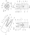
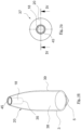
- Fig. 1 is an example based on a perspective view of an intermediate or intermediate product according to the invention for producing a projectile according to the invention or projectile of an ammunition, in particular a deformation projectile or a partial fragmentation projectile.
- the dashed lines are invisible contour edges according to a perspective view. To better illustrate the profile within the intermediate, the invisible contours are dashed.
- the intermediate according to the invention is generally provided with the reference number 1.
- the intermediate 1 consists of a blank which is cut to length from an approximately cylindrical rod section and is then inserted into a die which is not shown in detail. The blank is then cold-formed in order to achieve the design shape of the intermediate according to Fig. 1 to 4 to obtain.
- the intermediate 1 comprises a cylindrical, solid base end section 3 with a flat front face 5.
- the base end section 3 comprises an edge rounding on the flat front face 5 for easy insertion into a casing of an ammunition (not shown).
- the base end section 3 merges into a press end section 7, whereby the transition between the base end section 3 and the press end section 7 can be defined by a press recess 11 introduced into the blank.
- the press recess has a star shape, in which three slot arms 10a to 10c extend radially from an axial center (cavity 18 of the projectile 37) to the outside. These slot arms 10a to 10c form a completely continuous slot in a wall 12 of the press end section 7, which wall 12 is formed by the prongs 13 resulting from the slotting 10a to 10c.
- the slots 10a to 10c completely separate the prongs 13, with the slots 10a to 10c extending continuously from the radial outside of the intermediate 1 to the recess center (of the cavity 18) on the longitudinal axis A.
- the prongs 13 are therefore structurally separated from one another by the slotting.
- the cavity 18 results from the recess 11 (see Fig. 5 to 8 ), which is formed in particular during the deformation of the tines 13 into the ogive section 20. During this deformation, the tines extending cylindrically on the outside are used to form the ogivoid outer side is deformed radially inwards, wherein the cavity 18 is partially closed in the circumferential direction, in particular when the side edges 17 of the tines 13 are in contact.
- the pressing end section 7 comprises in the execution according to Fig. 1 to 4 three prongs 13 extending from the pressing end section, all of which have essentially the same external shape and are arranged in equidistant circumferential sections of approximately 120° to each other.
- Each prong 13 in the intermediate stage after Fig. 1 to 4 has a cylindrical outer surface 15 which ends at a lateral edge region 17 of the tine 13, at which the cylindrical outer surface 15 ends abruptly when viewed in the circumferential direction.
- a pair of inner flank surfaces 21, 23, which have a convex shape in both the axial direction and the circumferential direction, extend from the edge region 17 towards the pressing recess 11.
- the shape of the intermediate has the form of a solid sepal.
- Each tine 13 converges from the base end section 3 to a tine tip 25, wherein a circumferential width of each tine 13 decreases continuously starting from a foot of the tine in the transition region to the base end section 3 to the tine tip 25.
- each prong 13 comprises a material reinforcement or material accumulation 31 in the region of a center of the prong 13 in the longitudinal axis of the intermediate 1.
- the material accumulation 31 is responsible for a convex design of the inner side flank surfaces 21, 23 and represents an aspect for achieving a controlled deformation of the projectile 37 resulting from the intermediate 1, in particular when it is fired into a gelatin block (not shown in detail) according to the above-mentioned test methods.
- the material accumulation 31 extends essentially in a straight line from the tine tip 25 to the tine foot at the transition area to the base end section 3.
- a slotted bottom 33 for each of the slots 10a to 10c extends in the radial direction to a central recessed bottom 35, wherein the recessed bottom 35 is lower in side view than the further course of the slotted bottoms 33 in the radial direction.
- the slotted bottoms 33 rise from the central recessed bottom 35 in the radial direction.
- the slotted bottoms 33 are essentially flat or rounded and are approximately between 0.5 mm and 4 mm or 5 mm wide for a 9 mm bullet.
- the weakening of the intermediate 1 due to the deep-drawn recess 11 in combination with the subsequent deformation to form the ogive section 20 means that when the bullet 37 formed from the intermediate 1 hits, for example according to Fig. 5 to 8 , the material in the area of the slotted bottom serves as a forced deformation hinge, as it runs along the connecting line of two adjacent slotted bottoms 33.
- the plastic deformation hinge allows the prongs 13 to fold radially outwards, as is the case, for example, in the deformed projectile 81 according to Fig. 69 to 71
- the tines 83 are shaped like sepals or tongues and extend radially outwards.
- the slits 10a to 10c extend from the axial maximum extension of the tine tip 25 to the base end section 3 over more than 50% of the total length of the intermediate 1.
- the forming process for forming the projectile 37 mainly consists of forming the press end section 7 with the tines 13 separated by slots into an ogive section 20.
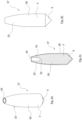
- the tines 13 are deformed radially inwards in such a way that the side edges 17 of the tines 13 come into or almost into contact, as shown in particular Fig. 5, 6 and 8 In the preferred version according to Fig. 1 to 8 the side edges 17 are brought into almost complete contact, up to a side through-opening 41 in the area of the slot bottom 33.
- the side through-opening 41 can be less than 1 mm in size and comprises a triangle, heart or spade shape.
- the side edges 17 are in contact with each other and form (in contrast to the prior art, which teaches only surface notches or weakening points) adjacent boundary surfaces that form a separating structure between the adjacent prongs 13.
- the adjacent side edges 17 extend up to the pointed end 43 of the ogive section 20, on which a particularly essentially star-shaped, centered opening 45 is formed, which serves to ensure that in the standardized test procedures gelatinous mass can penetrate, which by building up hydraulic pressure achieves the desired deformation (according to Fig. 69 to 71 ).
- the central opening 45 should be significantly smaller than 20% of the cylindrical cross section of the base end section 3. In the Fig. 5 to 8 In the projectile 37 shown, the opening cross-section of the opening 45 is approximately 10% or less of the cylindrical cross-section of the base end portion 3.
- the axial depth of the press recess 11 corresponds to about 20-30% of the total longitudinal extension of the intermediate 1, which fits well into the Figures 3.1 and 4.1
- the slot arms 10 a to 10 d do not form a complete radial opening in the wall 12 of the press end section 7. Rather, the wall 12 is cylindrically closed on the outside due to the slot bottoms 9, whereby the wall thickness at the axial end in the area of the press recess 11 is thin.
- the slot bottom 9 runs essentially straight with a constant gradient in the longitudinal direction to a recess bottom 35, which is circular and concave.
- the prongs 13 also open into the recess bottom 35.
- the prongs 13 have a convex shape on the cavity side with a ridge (material accumulation 31) that extends centrally towards the recess bottom 35.
- the outer surface 15 of the intermediate 1 is completely cylindrical, even at the level of the end face at which the press recess 11 is made.
- the press recess 11 can be made using a tool, as shown in the Figures 21-24 is shown, whereby other forms of an embossing die can also be used, as is known in the field of screwdriver bit shapes (screw head profile).
- the intermediate 1 After the intermediate 1 has been deep drawn without the need for any further machining operations, the intermediate 1 is ready to be formed into a projectile 37.
- the projectile 37 according to the Figures 5 to 8 are used for easy readability of the character description and to avoid repetition, the same reference numbers are used for the same or similar components of the projectile 37.
- the forming process for forming the projectile 37 mainly consists in forming the press end section 7 with the tines 13 separated by slots into an ogive section 20. The tines 13 are deformed radially inwards in such a way that the tines 13 come into or almost into contact, as is particularly evident Fig. 5.1 to 7.1 When executing according to Fig.
- the inner flank surfaces are brought approximately at least largely into contact to form a radially completely closed cavity 18 which extends from the recess base 35 in the axial longitudinal direction to the tip of the projectile 37, at which a funnel-shaped crater recess is formed.
- the outer surface of the ogive 20 is advantageously completely closed.
- a particularly substantially circular centered opening 45 is formed, which serves to allow gelatinous mass to penetrate during the standardized test procedures, which, by building up hydraulic pressure, achieves the desired deformation (according to Fig. 69 to 71 ).
- the central opening 45 should be significantly smaller than 20% of the cylindrical cross section of the base end section 3.
- the opening cross-section of the opening 45 is approximately 20% or less of the cylindrical cross-section of the base end section 3.
- the projectile 37 includes a slight bevel 27 in order to be able to cooperate more easily with an ammunition case.
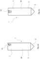
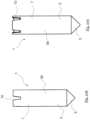
- a deep-drawing tool for producing intermediate 1 of the Fig. 1 to 4 or projectile 37 of the Fig. 5 to 8 In the inventive design of the tool for forming the intermediate 1, a classic known tool, namely a slotted screwdriver, is to be used, which in the embodiment according to Fig. 9 to 12 has a three-slot or three-web blade.
- Fig. 9 to 12 generally provided with the reference number 51, which comprises radially extending deformation webs 53 forming the slots 10a to 10c, which are separated by inner flank surfaces 55 which are concave substantially in the axial direction and in the circumferential direction.
- the maximum outer diameter of the tool 51 according to the invention according to Fig. 9 to 12 (also applies to the tools described later) is slightly larger than the caliber of the projectile 37 to be produced or the intermediate 1 to be manufactured. For example, the size difference is between 1 mm and 2 mm.
- the webs 53 are at an angle of 60° to one another in the cross-sectional view. From the top view it can be seen that the webs 53 are offset from one another at an angle of 120°, thus forming a point-symmetrical structure.
- the webs run to a central tip 51, which is rounded or spherical.
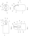
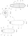
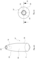
- FIG. 13 to 16 A further preferred embodiment of an intermediate 1 according to the invention is shown Fig. 13 to 16 .
- the same reference numerals are used for the identical or similar components of the intermediate 1 according to Fig. 1 to 4 used to prepare Intermediate 1 according to Fig. 13 to 16 to describe.
- the Intermediate 1 according to Fig. 13 to 16 differs from that according to Fig. 1 to 4 by the number of slots 10a to 10d and the number of prongs 13, namely four.
- the slotted bottoms 33 extend crosswise from the common recess bottom 35 in the radial direction outwards and rise ( Fig. 13 ).
- the tines have a convex, bulbous upper side towards the pressing recess 11, which reaches a maximum in the form of the material reinforcement 31.
- the tines 13 extend According to the undeformed intermediate 1, it is cylindrical on the outside and straight-lined and convex on the inside, slightly inclined outwards towards the tine tips 25.
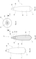
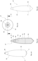
- Fig. 17 to 20 is the Intermediate 1 according to Fig. 13 to 16 converted into a projectile 37, whereby for better readability compared to the projectile 37 according to Fig. 5 to 8 the same reference symbols are used for similar or identical components.
- the projectile 37 according to Fig. 17 to 20 includes the projectile 37 according to Fig. 17 to 20 a significantly larger side opening 41, which has a triangular shape, the clear width of the side opening 41 gradually decreasing from the slot bottom to the prong tip 25.
- the touching side edges 17 of the prongs 13 only lie along a few millimeters in the pointed area, especially with a 9 mm caliber.
- the cavity 18 is closed in the short adjacent area in the circumferential direction, while the cavity 18 resulting from the press recess 11 is accessible laterally through the four side through-openings 41 and axially through the centered opening 45.
- the opening 45 at the tip of the ogive section which is centered in the longitudinal direction of the projectile, is essentially square with rounded corners.
- the cross-sectional area of the opening 45 is also significantly less than 20%, 15% or 10% of the cylindrical cross-sectional area of the base end section 3.
- the small cross-sectional area prevents components that are more solid than the gelatinous mass from closing the opening, which prevents the gelatinous material from penetrating into the cavity 18 to build up the hydraulic forces for splitting the tines 13.
- the tool 51 according to the invention with which the intermediate according to Fig. 13 to 16 shown is in Fig. 21 to 23 with the reference number 51. Identical and identical components of the tool are given the same reference numbers to simplify readability.
- the tool 51 according to Fig. 21 to 24 includes the tool 51 according to Fig. 21 to 24 four webs for forming four slots 10 in the wall of the press end section 7 of the intermediate 1.
- the four webs 53 are arranged at a right angle to each other.
- the flank surface areas include 55 between the webs 53 a concave shape in order to form the convex surface shape with the material reinforcement 31 of the intermediate 1.
- FIG. 25 to 28 a further preferred embodiment of the intermediate 1 according to the invention is shown, wherein the same reference numerals are used for the same and similar components of the intermediate 1 as in the embodiments already described above.
- Intermediate 1 has Fig. 25 to 28 only one slot extending completely from one radial side to the opposite side through the longitudinal axis center, as best shown in Fig. 26 can be seen.
- the slot 10 forms the pressing recess 11 and divides the wall for enclosing the cavity 18 into two prong sections 13, which tapers here to the tip 25 both in width direction and in material thickness.
- the same also applies to the prongs according to the other designs that have been described and will be described.
- the slotted bottom 33 is relatively wide and extends on the outer radial side by almost half the diameter of the base end section 3.
- the slotted bottom 33 tapers into the recess bottom 35, which is located centrally to the longitudinal axis A of the intermediate 1.
- the tines 13 facing the pressing recess 11 have a convexly shaped inner upper side which comprises a material reinforcement 31 which, as described above, extends from the tine tip 25 towards the recess bottom 35.
- the slotted bottom 33 rises at an angle of approximately 30° to 60°, approximately between 40° and 50°, particularly with respect to the longitudinal axis A.
- the slotted bottom runs essentially in a straight line radially outwards.
- Fig. 29 to 32 The product from Intermediate 1 according to Fig. 25 to 28 manufactured and especially formed projectile is in Fig. 29 to 32 shown, whereby the same reference numerals are used for the same reference numerals as in the projectile description already described above.
- the ogive section 20 comprises large side openings 41, which extend from the wide slotted bottom 33 of the intermediate 1 according to Fig. 25 to 28
- the clear cross-section of the side opening 41 decreases towards the tip of the ogive section 20.
- the bent prongs 13 delimit the cavity 18, which is accessible from the centered opening 45 and from the two side openings 41.
- a gap 61 is formed between the almost touching side edges 17 in the area of the central opening 45, which gap should be less than 2 mm or 1 mm wide.
- the central opening 45 in the region of the acute angle of the ogive section 20 has essentially an hourglass shape, wherein the clear cross-section of the opening 45 is significantly smaller than 20% or 10% of the cylindrical surface of the base end section 3.
- a special design of the ogive section 20 is visible, in which a bottle neck shape is provided at the pointed end of the wall, whereby the general ogive section design is different according to the other embodiments.
- FIG. 33 to 36 A further embodiment of the tool 51 according to the invention is shown, whereby for easier readability the same reference numerals are used as in the tool embodiments already described above.
- the press head 51 according to Fig. 33 to 36 comprises only two webs 53 for forming the two slots 10a and 10b according to the intermediate according to Fig. 25 to 28
- the concave flank surfaces 55 are particularly good in Fig. 33 and 35 visible.
- the execution of Intermediate 1 according to Fig. 37 to 40 differs from the execution of Intermediate 1 according to Fig. 13 to 16 in that the tine does not have a purely convex upper side facing the pressing depression 11, but rather a concave design with a linear material reduction 63 (notch or gap), which forms a split of the tine into two tine sections 13a and 13b, each of which ends in its own tine tip 25a, 25b.
- the "split" tines are structurally separated by four narrow slots 10a to 10d.
- the Intermediate 1 according to Fig. 37 to 40 has a convex curvature at least in the axial direction, but not in the circumferential direction, due to the reduction in material 63.
- Fig. 41 and 42 The projectile 37 according to the invention is based on the intermediate 1 according to Fig. 37 to 40 To make the description of the figures easier to read, the same reference numbers are used for the same and similar components of the projectile 37.
- the side opening 41 is smaller than half the longitudinal extension of the side edge 17.
- the side edges 17 are in contact with one another in order to delimit the cavity 18 in the circumferential direction.
- the intermediate 1 comprises a star shape at the pointed end of the ogive section 20, the clear cross-sectional area of which is significantly smaller than 20% of the cross-sectional area of the base end section 3.
- the cross-sectional area of the opening is smaller than 15% or 10%.
- the upper final edge in the area of the star-shaped central opening 45 forms the end edge of the respective prong 13, with side edges 17 touching one another.
- Fig. 45 to 48 the tool 51 according to the invention, namely the pressing head, is shown, with which the intermediate 1 according to Fig. 37 to 40
- the tool 51 has similar to the tool according to Fig. 21 to 24 four webs, wherein the flank surfaces 55 are convex at least in the circumferential direction with a height ridge 71.
- the four webs 53 extend at a right angle to each other.
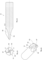
- FIG. 49 to 52 Another intermediate 1 according to the invention with a more complicated, non-axisymmetrical tine structure is shown.
- the structure of the intermediate 1 according to Fig. 49 to 52 comprises a press recess 11 which has continuous slots 10.
- the slots 10a to 10d extend radially somewhat outside, in particular tangentially to the depression bottom, to the longitudinal axis A of the intermediate 1.
- the tines 13 also have a convex upper side and grow integrally from the base end section 3. They reach a tine tip 25.
- the Intermediate 1 according to Fig. 49 to 52 is equivalent to a projectile 35 Fig. 56 to 59 bent over.
- the side openings 41 and the side edges 17 of the respective prongs extend helically with respect to the longitudinal axis A, which results from the non-purely radial slots 10a to 10d of the intermediate 1.
- the central opening 45 of the projectile 37 according to Fig. 56 to 59 has a smaller clear cross-sectional area than the cylindrical cross-sectional area of the base end portion 3.
- the clear cross-sectional area of the central opening 45 is significantly smaller than 20% or 15% or 10%.
- the cavity 18 is open laterally via the side openings 41 and the central opening 45. Approximately half of the axial length of the side edges 17 is in contact, so that the cavity is closed there in the circumferential direction. The other half of the side edges 17 are spaced apart to form the side opening 41.
- Fig. 53 to 55 the tool 51 according to the invention is shown, which serves to manufacture the intermediate 1 according to the invention.
- the four webs do not run centrally through the longitudinal axis of the tool, but are slightly offset tangentially to the pointed area 57. This offset creates the slightly twisted shape of the side edges 17 and the side opening 41.
- FIG. 60 to 63 a further embodiment of the intermediate 1 according to the invention is shown, wherein the same reference numerals are used for the same or similar components.
- the intermediate 1 comprises, as in the first described embodiment according to Fig. 1 to 4 three radially extending slots 10a to 10c, slightly offset from the longitudinal axis A. This results in the slots 10a to 10c as shown in Fig. 60 to 63
- the tines 13 end in a substantially flattened end 71.
- the surface facing the pressing recess 11 is convexly shaped, with its thickness decreasing in the axial direction towards the end 71.
- the according Fig. 60 to 63 The intermediate shown can be transformed into a projectile 37, which is not shown in detail in the figures.
- the inventive tool 51 according to Fig. 65 to 68 is designed to produce Intermediate 1 according to Fig. 61 to 63
- the webs 53 responsible for the slots 10a to 10c are also offset to the longitudinal axis of the tool 51 in order to introduce corresponding slot shapes into the intermediate 1.
- a deformed projectile according to the invention is shown, which essentially corresponds to the object of the invention according to Fig. 13 to 20
- the deformed projectile 81 comprises four tongue-like prongs 83 extending integrally from the base end portion 3, the shape of which can be described as sepal-like.
- the bent prongs 83 comprise a central reinforcement 33 which extends from the prong tip 25 to the recess bottom 35.
- the deformation of the prongs 83 can also be referred to as mushroom-shaped deformation.
- there is another tapered, radially outwardly extending projection 85 which essentially has the shape of a shark's tooth and extends radially outward in a convex shape.
- the teeth 85 extend above the deformed tines 83 and have a significantly shorter longitudinal extension than the deformed tines 83.
- the tapered teeth 85 result from a deformation in the region of the slot bottom 33 between the respective adjacent tines 83.
- the continuous slot design and the formation of a narrow slot bottom 33 in the region of the base end section 3 forces the formation of additional tapered teeth 85 between the bent tines 83.
- beak-shaped constrictions 87 form, which are typical of an ideal deformation under the above-mentioned test conditions.
- the deformed profile is approximately double-axis symmetrical and forms, in addition to the four folded prongs 85, four further radially outward-extending, in particular pointed teeth 85.
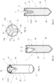
- Figures 72-75 show a further embodiment of an intermediate 1 according to the invention, wherein the same reference numerals are used for the same or similar components of the intermediate 1 for better readability of the figure description and to avoid repetitions.
- the intermediate 1 according to the Figures 72-77 is similar to Intermediate 1 according to the Figures 1-4 in that the press recess 11 forms three slot arms 10 a to c, which are arranged at equidistant intervals (120°) from one another.
- the slot arms 10 a to c are somewhat wider and run essentially radially evenly to the outside.
- the slots partially run radially continuously to the outer surface 15.
- the tines 13 are formed with the same shape as one another and have a convex inner flank surface 21 facing the cavity 18.
- the base body of the intermediate 1 is in two parts, namely formed by a core 38 and a jacket 39.
- the core 38 is a solid material, for example made of a ductile material such as copper or lead, which is completely surrounded by the thin-walled jacket 39, also made of a ductile material. Only the front side, at which the forming tool is moved in the axial direction A to form the pressing recess 11, is not covered by the casing 39.
- both the base body, the core 38, and the casing 39 adjacent to it are plastically deformed in order to create the desired slot (10).
- the intermediate 1 has a conical end shape on the front side 5 opposite the pressing end section 7.
- the casing 39 protrudes slightly axially at the pressing end section 7 so that no material of the core 38 can protrude beyond the edge of the casing 39.
- the forming process for forming the projectile 37 mainly consists of forming, in particular pressing, the press end section 7 with the tines 13 separated by slots into a suitable ogive section 20.
- the tines 13 are deformed radially inwards in such a way that the side edges 17 of the Prongs 13 come into contact, as in particular Fig. 78 to 83 In the preferred version according to Fig. 78 to 82 the side edges 17 are brought into complete contact until a completely closed outer surface 15 has been formed in the region of the cavity 18 and the slot arms 10 of the intermediate 1.
- the cavity 18 extends cylindrically from the recess bottom 35 to the end 43 of the ogive section 20, on which a particularly substantially circular, centered opening 45 is formed, which serves to allow a gelatinous mass to penetrate during the standardized test procedures, which, by building up hydraulic pressure, achieves the desired deformation (according to Fig. 69 to 71 ).
- the central opening 45 should be significantly smaller than 20% of the cylindrical cross section of the base end section 3. In the Fig. 5 to 8 In the projectile 37 shown, the opening cross-section of the opening 45 is approximately 20% or less of the cylindrical cross-section of the base end portion 3.
- a variant of the projectile 37 is in the Figures 83-87
- the same references are used for the same components of the projectile 37.
- the projectile, in particular a partial fragmentation device, 37 according to the Figures 83 to 87 differs from the projectile 37 according to the Figures 78 to 82 in that a tip 86, in particular made of plastic, is inserted into the central opening 45 in order to make the ogive section 20 aerodynamically pointed.
- the tip 86 has a substantially symmetrical structure and two blind hole recesses 84, 88, one (84) on the open outside of the tip 86 and another (88) on the insertion area that engages in the cavity 18 of the projectile 37.
- the tip 86 can already be pre-assembled so that pressing forces are communicated during forming to hold the tip 86.
- the latter In order to provide a defined axial position of the tip 86, the latter has a circumferential shoulder 89 against which the round end edge of the casing 39 rests.
- the Figures 88-93 show a further variant of an intermediate 1 according to the invention, wherein the same reference numerals as above are used for the similar or identical components.
- the intermediate 1 according to the Figures 88-93 differs from the intermediate according to the Figures 72-77 by the fact that the core 38 is two-part namely a deformation section 91, in particular made of a solid material, for example of a ductile material such as copper or lead, in which the press recess 11 is introduced, and an undeformed, rear-side core section 93, in particular made of a solid material, for example of a ductile material such as copper or lead.
- the core section 93 is somewhat smaller and represents more than half, for example 2/3, of the total length of the intermediate 1.
- the deformation section 90 and the rear-side core section 93 are used for the deformation section 90 and the rear-side core section 93.
- the same material can also be used, with an interface 95 being formed between the two sections 91, 93.
- the press recess 11 is introduced exclusively in the deformation section 91, with the recess base 35 being positioned close to the interface 95 between the deformation section 91 and the core section 93.
- the projectile 37 in particular a partial fragmentation device, which is formed from the intermediate 1 according to the Figures 88-93 is in the Figures 94-97 in a 1st version and in the Figures 99-103 in a second embodiment, the second embodiment differing only in that the tip 86 described above is inserted into the cavity 18.
- the projectile 37 according to the first and second embodiment differs from the projectile 37 according to the Figures 78-87 in the 2-part core, the deformation section 91 and the core section 93, wherein the deformation section 91 is located essentially in the region of the ogive section 20; however, it can also extend significantly (at the expense of the core section 93) towards the rear and take up a larger part of the core 38.
- the inventive embodiment of the intermediate 1 according to the Figures 104 to 109 differs from Intermediate 1 according to the Figures 72-77 in that instead of three slotted arms 10 (three prongs 13) four slotted arms 10 a to d (prongs 13) are provided.
- the same reference numbers as above are used.
- From the intermediate 1 according to the Figures 104-109 The approximately identical projectile 37, which was used in the Figures 110-115 shown, as in the intermediate 1 with three prongs 13. By increasing/reducing the number of prongs, the geometry of the ogive 20 or the cavity 18 can be adjusted.
- the projectile 37 according to the 2nd version with the tip 86 according to the Figures 115-119 is approximately equal to the above described projectile 83-87 according to the figures.
- the inventive embodiment of the intermediate 1 according to the Figures 120 to 125 differs from Intermediate 1 according to the Figures 88-93 in that instead of three slotted arms 10 (three prongs 13) four slotted arms 10 a to d (prongs 13) are provided.
- the same reference numbers as above are used. From the intermediate 1 according to the Figures 120-125 can be almost the same, in the Figures 126-129 shown projectile 37, as in the intermediate 1 with three prongs 13 according to the Figures 94-97
- the geometry of the ogive 20 or the cavity 18 can be adjusted.
- the projectile 37 according to the 2nd version with the tip 86 according to the Figures 131-135 is the above described projectile 37 according to the Figures 115 to 119 approximately the same.
- the features disclosed in the above description, the figures and the claims can be important both individually and in any combination for the realization of the invention in the various embodiments.
Landscapes
- Engineering & Computer Science (AREA)
- General Engineering & Computer Science (AREA)
- Chemical & Material Sciences (AREA)
- Combustion & Propulsion (AREA)
- Physics & Mathematics (AREA)
- Fluid Mechanics (AREA)
- Mechanical Engineering (AREA)
- Thermal Sciences (AREA)
- Manufacturing & Machinery (AREA)
- Adornments (AREA)
- Containers And Packaging Bodies Having A Special Means To Remove Contents (AREA)
- Forging (AREA)
- Toys (AREA)
- Aiming, Guidance, Guns With A Light Source, Armor, Camouflage, And Targets (AREA)
Applications Claiming Priority (3)
| Application Number | Priority Date | Filing Date | Title |
|---|---|---|---|
| DE102017011359.9A DE102017011359A1 (de) | 2017-12-08 | 2017-12-08 | Intermediat zum Fertigen von Projektilen eines Deformationsgeschosses, Projektil, deformiertes Projektil, Werkzeug zum Fertigen des Intermediats und Verfahren zum Herstellen des Intermediats |
| PCT/EP2018/084238 WO2019110850A1 (fr) | 2017-12-08 | 2018-12-10 | Intermédiaire servant à produire des projectiles d'une balle à déformation, projectile, projectile déformé, outil servant à produire l'intermédiaire et procédé servant à fabriquer l'intermédiaire |
| EP18825910.5A EP3721166B1 (fr) | 2017-12-08 | 2018-12-10 | Projectile |
Related Parent Applications (1)
| Application Number | Title | Priority Date | Filing Date |
|---|---|---|---|
| EP18825910.5A Division EP3721166B1 (fr) | 2017-12-08 | 2018-12-10 | Projectile |
Publications (3)
| Publication Number | Publication Date |
|---|---|
| EP4455606A2 true EP4455606A2 (fr) | 2024-10-30 |
| EP4455606A3 EP4455606A3 (fr) | 2025-01-15 |
| EP4455606B1 EP4455606B1 (fr) | 2026-03-04 |
Family
ID=64870422
Family Applications (2)
| Application Number | Title | Priority Date | Filing Date |
|---|---|---|---|
| EP18825910.5A Active EP3721166B1 (fr) | 2017-12-08 | 2018-12-10 | Projectile |
| EP24191821.8A Active EP4455606B1 (fr) | 2017-12-08 | 2018-12-10 | Projectile |
Family Applications Before (1)
| Application Number | Title | Priority Date | Filing Date |
|---|---|---|---|
| EP18825910.5A Active EP3721166B1 (fr) | 2017-12-08 | 2018-12-10 | Projectile |
Country Status (12)
| Country | Link |
|---|---|
| US (2) | US11561074B2 (fr) |
| EP (2) | EP3721166B1 (fr) |
| BR (1) | BR112020011468B1 (fr) |
| CA (1) | CA3084874A1 (fr) |
| DE (1) | DE102017011359A1 (fr) |
| DK (1) | DK3721166T3 (fr) |
| ES (1) | ES2991025T3 (fr) |
| FI (1) | FI3721166T3 (fr) |
| PL (1) | PL3721166T3 (fr) |
| PT (1) | PT3721166T (fr) |
| SI (1) | SI3721166T1 (fr) |
| WO (1) | WO2019110850A1 (fr) |
Families Citing this family (9)
| Publication number | Priority date | Publication date | Assignee | Title |
|---|---|---|---|---|
| DE102019135875A1 (de) * | 2019-12-30 | 2021-07-01 | Ruag Ammotec Ag | Vollgeschoss, Intermediat zum Fertigen eines Vollgeschosses und Verfahren zum Herstellen eines Vollgeschosses |
| USD1110460S1 (en) * | 2020-02-28 | 2026-01-27 | Sako Oy | Bullet |
| DE102021104757A1 (de) | 2021-02-26 | 2022-09-01 | Ruag Ammotec Ag | Metallisches Übungspatronen-Geschoss |
| DE102021104760A1 (de) | 2021-02-26 | 2022-09-01 | Ruag Ammotec Ag | Deformationsgeschoss für Polizei- und Behördenmunition |
| US11598616B1 (en) * | 2021-09-07 | 2023-03-07 | True Velocity Ip Holdings, Llc | Vented hollow point projectile |
| DE102022104617A1 (de) * | 2022-02-25 | 2023-08-31 | Ruag Ammotec Ag | Intermediat, Werkzeug und Verfahren zum Herstellen eines Deformationsgeschosses mit definierter Endballistik |
| DE102022113108A1 (de) | 2022-05-24 | 2023-11-30 | Ruag Ammotec Gmbh | Werkzeug und Verfahren zum Fertigen eines Projektils sowie Projektil |
| USD1049298S1 (en) * | 2023-02-14 | 2024-10-29 | Halo Ammunition, LLC | Bullet with fins |
| DE102024125029A1 (de) | 2024-09-02 | 2026-03-05 | IBB Industrie Beteiligung und Beratung GmbH & Co. KG | Hohlspitzgeschoss |
Citations (2)
| Publication number | Priority date | Publication date | Assignee | Title |
|---|---|---|---|---|
| US5259320A (en) | 1989-06-29 | 1993-11-09 | Barnes Bullets, Inc. | Intermediate article used to form a bullet projectile or component and a finally formed bullet |
| WO2015061662A1 (fr) | 2013-10-24 | 2015-04-30 | G2 Research Inc. | Projectile à fragmentation |
Family Cites Families (25)
| Publication number | Priority date | Publication date | Assignee | Title |
|---|---|---|---|---|
| US219840A (en) * | 1879-09-23 | Improvement in methods of manufacturing bullets | ||
| US1101743A (en) * | 1914-02-24 | 1914-06-30 | Union Metallic Cartridge Co | Hollow-point bullet. |
| US2045964A (en) * | 1934-12-13 | 1936-06-30 | Berlin Karlsruher Ind Werke Ag | Casing projectile |
| DE2909471A1 (de) * | 1979-03-10 | 1980-09-11 | Schirnecker Hans Ludwig | Geschoss, beispielsweise fuer jagdzwecke, und verfahren zu seiner herstellung |
| US4882822A (en) * | 1988-01-04 | 1989-11-28 | Burczynski Thomas J | Method of fabrication of a bullet having sections separable upon impact |
| DE3838584A1 (de) * | 1988-11-14 | 1990-05-23 | Karl Klaus Mayer | Geschoss der deformations-klasse, fuer jagd - buechsenpatronen |
| DE4111959C2 (de) | 1991-04-12 | 1993-10-14 | Herbert Haefner | Vollgeschoß |
| DE4435859A1 (de) * | 1994-10-07 | 1996-04-18 | Herbert Haefner | Vollgeschoß |
| AT405977B (de) * | 1996-04-24 | 2000-01-25 | Winter Udo Mag Ing | Expansionsgeschoss |
| US6457417B1 (en) * | 1997-04-16 | 2002-10-01 | Doris Nebel Beal Inter Vivos Patent Trust | Method for the manufacture of a frangible nonsintered powder-based projectile for use in gun ammunition and product obtained thereby |
| US5943749A (en) * | 1997-11-04 | 1999-08-31 | The Nippert Company | Method of manufacturing a hollow point bullet |
| SE520088C2 (sv) * | 2000-04-06 | 2003-05-20 | Skf Sverige Ab | Metod för spånskärande bearbetning av ett arbetsstycke |
| US6805057B2 (en) * | 2000-11-10 | 2004-10-19 | Federal Cartridge Corporation | Bullet for optimal penetration and expansion |
| EP1864077A1 (fr) * | 2005-03-17 | 2007-12-12 | CBC Companhia Brasileira de Cartuchos | Projectile a expansion pour armes a feu |
| US8171852B1 (en) * | 2006-10-24 | 2012-05-08 | Peter Rebar | Expanding projectile |
| DE102013014693A1 (de) * | 2012-09-06 | 2014-03-06 | Ruag Ammotec Gmbh | Geschoss für Schießstand- und Übungspatronen |
| US9383178B2 (en) * | 2014-02-06 | 2016-07-05 | Sig Sauer, Inc. | Hollow point bullet and method of manufacturing same |
| CA2940332A1 (fr) | 2014-02-25 | 2015-09-03 | Ruag Ammotec Gmbh | Projectile a deformation enduit |
| US9677862B2 (en) * | 2014-04-17 | 2017-06-13 | Maker Holdings, LLC | Mutli-stage fragmenting projectile |
| USD782602S1 (en) * | 2015-03-18 | 2017-03-28 | Sig Sauer, Inc. | Pellet |
| USD770005S1 (en) * | 2015-03-18 | 2016-10-25 | Silencerco, Llc | Projectile |
| USD821536S1 (en) * | 2016-08-24 | 2018-06-26 | Silencerco, Llc | Projectile |
| US20180161972A1 (en) * | 2016-12-09 | 2018-06-14 | Yun Chan Industry Co., Ltd. | Screwdriver tool with identification structure |
| US10690464B2 (en) * | 2017-04-28 | 2020-06-23 | Vista Outdoor Operations Llc | Cartridge with combined effects projectile |
| US11460279B2 (en) * | 2017-07-17 | 2022-10-04 | Olin Corporation | Fragmenting bullet |
-
2017
- 2017-12-08 DE DE102017011359.9A patent/DE102017011359A1/de active Pending
-
2018
- 2018-12-10 SI SI201831165T patent/SI3721166T1/sl unknown
- 2018-12-10 US US16/770,852 patent/US11561074B2/en active Active
- 2018-12-10 ES ES18825910T patent/ES2991025T3/es active Active
- 2018-12-10 EP EP18825910.5A patent/EP3721166B1/fr active Active
- 2018-12-10 PT PT188259105T patent/PT3721166T/pt unknown
- 2018-12-10 WO PCT/EP2018/084238 patent/WO2019110850A1/fr not_active Ceased
- 2018-12-10 CA CA3084874A patent/CA3084874A1/fr active Pending
- 2018-12-10 DK DK18825910.5T patent/DK3721166T3/da active
- 2018-12-10 BR BR112020011468-5A patent/BR112020011468B1/pt active IP Right Grant
- 2018-12-10 FI FIEP18825910.5T patent/FI3721166T3/fi active
- 2018-12-10 PL PL18825910.5T patent/PL3721166T3/pl unknown
- 2018-12-10 EP EP24191821.8A patent/EP4455606B1/fr active Active
-
2022
- 2022-12-07 US US18/076,554 patent/US11879709B2/en active Active
Patent Citations (2)
| Publication number | Priority date | Publication date | Assignee | Title |
|---|---|---|---|---|
| US5259320A (en) | 1989-06-29 | 1993-11-09 | Barnes Bullets, Inc. | Intermediate article used to form a bullet projectile or component and a finally formed bullet |
| WO2015061662A1 (fr) | 2013-10-24 | 2015-04-30 | G2 Research Inc. | Projectile à fragmentation |
Also Published As
| Publication number | Publication date |
|---|---|
| BR112020011468A2 (pt) | 2020-11-17 |
| EP4455606B1 (fr) | 2026-03-04 |
| EP3721166A1 (fr) | 2020-10-14 |
| DE102017011359A1 (de) | 2019-06-13 |
| PL3721166T3 (pl) | 2024-11-25 |
| US11879709B2 (en) | 2024-01-23 |
| CA3084874A1 (fr) | 2019-06-13 |
| US11561074B2 (en) | 2023-01-24 |
| DK3721166T3 (da) | 2024-09-23 |
| WO2019110850A1 (fr) | 2019-06-13 |
| FI3721166T3 (fi) | 2024-11-01 |
| EP3721166B1 (fr) | 2024-07-31 |
| BR112020011468B1 (pt) | 2023-10-17 |
| SI3721166T1 (sl) | 2025-03-31 |
| PT3721166T (pt) | 2024-10-11 |
| US20200370872A1 (en) | 2020-11-26 |
| ES2991025T3 (es) | 2024-12-02 |
| EP4455606A3 (fr) | 2025-01-15 |
| US20230117770A1 (en) | 2023-04-20 |
Similar Documents
| Publication | Publication Date | Title |
|---|---|---|
| EP3721166B1 (fr) | Projectile | |
| EP2019214B1 (fr) | Elément destiné à être inséré à force dans un composant non percé ou percé et procédé de fabrication d'un tel élément | |
| AT407301B (de) | Deformationsgeschoss, damit ausgerüstete munition, sowie verfahren zur herstellung des geschosses | |
| DE3323254C2 (de) | Blindbolzen mit Sperrkragen | |
| EP1886030B1 (fr) | Rivet | |
| EP1229254B1 (fr) | Liaison par rivetage poinçonnant et rivet poinçonnant creux | |
| EP2191152B1 (fr) | Utilisation d'un rivet aveugle et procédé de placement d'un rivet aveugle | |
| DE202012100361U1 (de) | Expansionskopf für Aufweitwerkzeuge und diesen umfassendes Expansionswerkzeug | |
| EP3690260A1 (fr) | Rivet auto-poinçonneur semi-tubulaire, raccordement riveté d'au moins deux composants à l'aide du rivet auto-poinçonneur semi-tubulaire ainsi que procédé de raccordement des composants au rivet auto-poinçonneur semi-tubulaire | |
| EP3983749B1 (fr) | Projectile, en particulier balle à déformation et/ou à décomposition partielle. | |
| DE102018119075A1 (de) | Spreizanker | |
| DE3722024A1 (de) | Einlage fuer einen gefechtskopf | |
| EP2087245B1 (fr) | Rivet | |
| DE102008013227A1 (de) | Verfahren zum Herstellen einer Verbindung zwischen einer Welle und einem Hülsenabschnitt | |
| WO2015022161A1 (fr) | Rivet auto-poinçonneur semi-tubulaire pour l'assemblage sans pré-trou d'un composant en matière synthétique renforcée par des fibres à un composant métallique | |
| DE19930473A1 (de) | Deformationsgeschoß | |
| EP2609342B1 (fr) | Élément de fixation | |
| DE102019102380A1 (de) | Vollstanzniet, eine Stanznietverbindung aus mindestens zwei Bauteilen mithilfe des Vollstanzniets sowie ein Verfahren zum Verbinden der Bauteile mit dem Vollstanzniet | |
| DE102022104617A1 (de) | Intermediat, Werkzeug und Verfahren zum Herstellen eines Deformationsgeschosses mit definierter Endballistik | |
| DE102021133544A1 (de) | Halbhohlstanzniet mit tiefer Schaftbohrung | |
| CH687788A5 (de) | Deformationsgeschoss, damit ausgeruestete Munition, sowie Verfahren zur Herstellung des Geschosses. | |
| EP3803138A1 (fr) | Boulon conique et procédé de production d'un boulon conique | |
| DE102021112716A1 (de) | Halbhohlstanzniet, eine Stanznietverbindung aus mindestens zwei Bauteilen mithilfe des Halbhohlstanzniets, ein Herstellungsverfahren des Halbhohlstanzniets sowie ein Verfahren zum Verbinden der Bauteile mit dem Halbhohlstanzniet | |
| DE102024109594A1 (de) | Tiefgezogene Hybridhülse | |
| DE102024109615A1 (de) | Tiefgezogene Hybridhülse |
Legal Events
| Date | Code | Title | Description |
|---|---|---|---|
| PUAI | Public reference made under article 153(3) epc to a published international application that has entered the european phase |
Free format text: ORIGINAL CODE: 0009012 |
|
| STAA | Information on the status of an ep patent application or granted ep patent |
Free format text: STATUS: THE APPLICATION HAS BEEN PUBLISHED |
|
| AC | Divisional application: reference to earlier application |
Ref document number: 3721166 Country of ref document: EP Kind code of ref document: P |
|
| AK | Designated contracting states |
Kind code of ref document: A2 Designated state(s): AL AT BE BG CH CY CZ DE DK EE ES FI FR GB GR HR HU IE IS IT LI LT LU LV MC MK MT NL NO PL PT RO RS SE SI SK SM TR |
|
| PUAL | Search report despatched |
Free format text: ORIGINAL CODE: 0009013 |
|
| AK | Designated contracting states |
Kind code of ref document: A3 Designated state(s): AL AT BE BG CH CY CZ DE DK EE ES FI FR GB GR HR HU IE IS IT LI LT LU LV MC MK MT NL NO PL PT RO RS SE SI SK SM TR |
|
| RIC1 | Information provided on ipc code assigned before grant |
Ipc: F42B 33/00 20060101ALI20241212BHEP Ipc: F42B 12/34 20060101AFI20241212BHEP |
|
| STAA | Information on the status of an ep patent application or granted ep patent |
Free format text: STATUS: REQUEST FOR EXAMINATION WAS MADE |
|
| 17P | Request for examination filed |
Effective date: 20250415 |
|
| GRAP | Despatch of communication of intention to grant a patent |
Free format text: ORIGINAL CODE: EPIDOSNIGR1 |
|
| STAA | Information on the status of an ep patent application or granted ep patent |
Free format text: STATUS: GRANT OF PATENT IS INTENDED |
|
| INTG | Intention to grant announced |
Effective date: 20251117 |
|
| GRAS | Grant fee paid |
Free format text: ORIGINAL CODE: EPIDOSNIGR3 |
|
| GRAA | (expected) grant |
Free format text: ORIGINAL CODE: 0009210 |
|
| STAA | Information on the status of an ep patent application or granted ep patent |
Free format text: STATUS: THE PATENT HAS BEEN GRANTED |
|
| AC | Divisional application: reference to earlier application |
Ref document number: 3721166 Country of ref document: EP Kind code of ref document: P |
|
| AK | Designated contracting states |
Kind code of ref document: B1 Designated state(s): AL AT BE BG CH CY CZ DE DK EE ES FI FR GB GR HR HU IE IS IT LI LT LU LV MC MK MT NL NO PL PT RO RS SE SI SK SM TR |
|
| REG | Reference to a national code |
Ref country code: CH Ref legal event code: F10 Free format text: ST27 STATUS EVENT CODE: U-0-0-F10-F00 (AS PROVIDED BY THE NATIONAL OFFICE) Effective date: 20260304 Ref country code: GB Ref legal event code: FG4D Free format text: NOT ENGLISH |
|
| REG | Reference to a national code |
Ref country code: DE Ref legal event code: R096 Ref document number: 502018016443 Country of ref document: DE |
|
| REG | Reference to a national code |
Ref country code: IE Ref legal event code: FG4D Free format text: LANGUAGE OF EP DOCUMENT: GERMAN |