EP4455754A2 - Système optique, module de caméra et dispositif terminal - Google Patents
Système optique, module de caméra et dispositif terminal Download PDFInfo
- Publication number
- EP4455754A2 EP4455754A2 EP24194988.2A EP24194988A EP4455754A2 EP 4455754 A2 EP4455754 A2 EP 4455754A2 EP 24194988 A EP24194988 A EP 24194988A EP 4455754 A2 EP4455754 A2 EP 4455754A2
- Authority
- EP
- European Patent Office
- Prior art keywords
- lens
- optical system
- optical axis
- object side
- refractive power
- Prior art date
- Legal status (The legal status is an assumption and is not a legal conclusion. Google has not performed a legal analysis and makes no representation as to the accuracy of the status listed.)
- Pending
Links
Images




Classifications
-
- G—PHYSICS
- G02—OPTICS
- G02B—OPTICAL ELEMENTS, SYSTEMS OR APPARATUS
- G02B13/00—Optical objectives specially designed for the purposes specified below
- G02B13/001—Miniaturised objectives for electronic devices, e.g. portable telephones, webcams, PDAs, small digital cameras
- G02B13/0015—Miniaturised objectives for electronic devices, e.g. portable telephones, webcams, PDAs, small digital cameras characterised by the lens design
-
- G—PHYSICS
- G02—OPTICS
- G02B—OPTICAL ELEMENTS, SYSTEMS OR APPARATUS
- G02B9/00—Optical objectives characterised both by the number of the components and their arrangements according to their sign, i.e. + or -
- G02B9/62—Optical objectives characterised both by the number of the components and their arrangements according to their sign, i.e. + or - having six components only
-
- G—PHYSICS
- G02—OPTICS
- G02B—OPTICAL ELEMENTS, SYSTEMS OR APPARATUS
- G02B13/00—Optical objectives specially designed for the purposes specified below
- G02B13/001—Miniaturised objectives for electronic devices, e.g. portable telephones, webcams, PDAs, small digital cameras
- G02B13/0015—Miniaturised objectives for electronic devices, e.g. portable telephones, webcams, PDAs, small digital cameras characterised by the lens design
- G02B13/002—Miniaturised objectives for electronic devices, e.g. portable telephones, webcams, PDAs, small digital cameras characterised by the lens design having at least one aspherical surface
- G02B13/0045—Miniaturised objectives for electronic devices, e.g. portable telephones, webcams, PDAs, small digital cameras characterised by the lens design having at least one aspherical surface having five or more lenses
-
- G—PHYSICS
- G02—OPTICS
- G02B—OPTICAL ELEMENTS, SYSTEMS OR APPARATUS
- G02B13/00—Optical objectives specially designed for the purposes specified below
- G02B13/04—Reversed telephoto objectives
-
- G—PHYSICS
- G02—OPTICS
- G02B—OPTICAL ELEMENTS, SYSTEMS OR APPARATUS
- G02B13/00—Optical objectives specially designed for the purposes specified below
- G02B13/18—Optical objectives specially designed for the purposes specified below with lenses having one or more non-spherical faces, e.g. for reducing geometrical aberration
-
- G—PHYSICS
- G02—OPTICS
- G02B—OPTICAL ELEMENTS, SYSTEMS OR APPARATUS
- G02B13/00—Optical objectives specially designed for the purposes specified below
- G02B13/001—Miniaturised objectives for electronic devices, e.g. portable telephones, webcams, PDAs, small digital cameras
- G02B13/0055—Miniaturised objectives for electronic devices, e.g. portable telephones, webcams, PDAs, small digital cameras employing a special optical element
- G02B13/006—Miniaturised objectives for electronic devices, e.g. portable telephones, webcams, PDAs, small digital cameras employing a special optical element at least one element being a compound optical element, e.g. cemented elements
Definitions
- the subject matter relates to field of optical imaging, and more particularly, to an optical system, a camera module, and a terminal device.
- the present application provides an optical system, a camera module, and a terminal device.
- the present application provides an optical system.
- the optical system consists of six lenses having refractive power. From an object side to an image side along an optical axis of the optical system, the six lenses sequentially include a first lens, a second lens, a third lens, a fourth lens, a fifth lens, and a sixth lens.
- the first lens has negative refractive power, and an image side surface of the first lens is concave near the optical axis.
- the second lens has negative refractive power, an object side surface of the second lens is concave near the optical axis, and an image side surface of the second lens is convex near the optical axis.
- the third lens has positive refractive power, an object side surface of the third lens is convex near the optical axis, and an image side surface of the third lens is convex near the optical axis.
- the fourth lens has refractive power.
- the fifth lens has refractive power.
- the sixth lens has refractive power, and an object side a refractive of the sixth lens is convex near the optical axis.
- the optical system satisfies following relational expression: 1.2 ⁇ IMGH/EPD ⁇ 1.4. Wherein, IMGH is half of an image height corresponding to a maximum field of view of the optical system, and EPD is an entrance pupil diameter of the optical system.
- the second lens has negative refractive power, which may allow the incident rays from the first lens to gently enter the optical system.
- the object side surface of the second lens is concave near the optical axis and the image side surface of the second lens is convex near the optical axis, which may correct off-axis aberrations, thereby reducing the sensitivity of the optical system to changes in resolution and enhancing the imaging stability of the optical system.
- the imaging quality of the optical system may be improved.
- the rays collected by the first and second lenses may be compressed, thereby achieving gently transition of the incident rays to improve the relative illumination of the optical system.
- the rays at the central and marginal fields may be converged, thereby correcting marginal field aberrations and improving the resolution ability of the optical system.
- the object side surface of the sixth lens is convex near the optical axis, which may correct the astigmatism of the optical system, improve the imaging quality of the optical system, and facilitate the miniaturization design of the optical system.
- the optical system satisfies the relational expression of 1.2 ⁇ IMGH/EPD ⁇ 1.4.
- a large aperture of the optical system may be achieved, thereby ensuring that the optical system meets the sufficient image brightness in the marginal field and thus improving the imaging quality of the optical system.
- curvature of field may be avoided, which may improve the resolution of the optical system.
- the entrance pupil diameter of the optical system is too small relative to the image height, which may not achieve large aperture and improve the image brightness.
- it is below the lower limit of the above relational expression the entrance pupil diameter of the optical system is too large relative to the image height, which may not reduce the astigmatism of the marginal field.
- the present application provides a camera module.
- the camera module includes an image sensor and the optical system mentioned in the first aspect.
- the image sensor is located on an image side of the optical system.
- the camera module including the optical system may have large aperture and high imaging quality while maintaining a lightweight and compact design.
- the present application provides a terminal device.
- the terminal device includes a fixing member and the camera module mentioned in the second aspect.
- the camera module is located on the fixing member.
- the terminal device including the camera module may have large aperture and high imaging quality while maintaining a lightweight and compact design.
- the present application discloses an optical system.
- the optical system consists of six lenses with refractive power.
- the six lenses sequentially include a first lens, a second lens, a third lens, a fourth lens, a fifth lens, and a sixth lens from an object side to an image side along an optical axis.
- rays enter the first lens from the object side of the first lens, then sequentially enter the second lens, the third lens, the fourth lens, the fifth lens, and the sixth lens, and finally form images on an imaging surface of the optical system.
- the first lens has negative refractive power
- the second lens has negative refractive power
- the third lens has positive refractive power
- the fourth lens has positive or negative refractive power
- the fifth lens has positive or negative refractive power
- the sixth lens has positive or negative refractive power.
- an object side surface of the first lens is convex or concave near the optical axis, and an image side surface of the first lens is concave near the optical axis.
- An object side surface of the second lens is concave near the optical axis, and an image side surface of the second lens is convex near the optical axis.
- An object side surface of the third lens is convex near the optical axis, and an image side surface of the third lens is convex near the optical axis.
- An object side surface of the fourth lens is concave or convex near the optical axis, and an image side surface of the fourth lens is concave or convex near the optical axis.
- An object side surface of the fifth lens is convex or concave near the optical axis, and an image side surface of the fifth lens is convex or concave near the optical axis.
- An object side surface of the sixth lens is convex near the optical axis, and an image side surface of the sixth lens is concave or convex near the optical axis.
- the second lens has negative refractive power, which may allow the incident rays from the first lens to gently enter the optical system.
- the object side surface of the second lens is concave near the optical axis and the image side surface of the second lens is convex near the optical axis, which may correct off-axis aberrations, thereby reducing the sensitivity of the optical system to changes in resolution and enhancing the imaging stability of the optical system.
- the imaging quality of the optical system may be improved.
- the rays collected by the first and second lenses may be compressed, thereby achieving gently transition of the incident rays to improve the relative illumination of the optical system.
- the rays at the central and marginal fields may be converged, thereby correcting marginal field aberrations and improving the resolution ability of the optical system.
- the object side surface of the sixth lens is convex near the optical axis, which may correct the astigmatism of the optical system, improve the imaging quality of the optical system, and facilitate the miniaturization design of the optical system.
- the first lens and the third lenses are made of glass. At least two of the second lens, the fourth lens, the fifth lens, and the sixth lens are made of plastic.
- the optical system may have a low temperature drift sensitivity and small overall weight.
- all of the first lens, the second lens, the third lens, the fourth lens, the fifth lens, and the sixth lens may be made of plastic, which may further reduce the weight and cost of the optical system.
- All of the lenses may also be made of glass, thereby allowing the optical system to have a better optical effect and a lower temperature drift sensitivity.
- the material of each lens of the optical system may be selected according to actual needs. For example, all of the lenses may be made of plastic or glass.
- the optical system may also include the lenses of different materials.
- spherical lenses may have simple manufacturing process, low production cost, facilitates flexible design of the surface shape of the lens, and improve the resolution ability of the optical system.
- Aspherical lenses may provide a more flexible design for the object side surface or image side surface of the lens, allowing the lens to solve problems such as unclear imaging, distorted field of view, or narrow field of view even when the lens has a small and thin size.
- the optical systems may have good imaging quality without too many lenses, which may reduce the length of the optical system. Therefore, the first lens and the third lens may be spherical lenses, while the second lens, the fourth lens, the fifth lens, and the sixth lens are aspherical lenses.
- each lens By including the spherical and aspherical lenses, the processability of each lens may be improved, which may be beneficial for surface design of each lens. Also, the object or image side surface of the lens may be designed more flexibly. Thus, problems such as unclear imaging, distorted field of view, or narrow field of view may be solved even when each lens has a small and thin size, and the optical system may have good imaging quality without too many lenses, which may reduce the length of the optical system.
- the surfaces of each lens of the optical system may be all spherical, all aspherical, or any combination of spherical and aspherical surfaces, which may be selected according to actual needs.
- the optical system further includes an aperture stop, which may be an aperture stop and/or a field aperture stop.
- the aperture stop may be an aperture stop.
- the aperture stop may also be a field aperture stop.
- the aperture stop may also be a combination of the aperture stop and the field aperture stop.
- the optical system further includes an infrared filter.
- the infrared filter is arranged between the sixth lens and the imaging surface of the optical system.
- the infrared filter may be an infrared cutoff filter, which filters out infrared rays and allows visible rays to pass through, thereby allowing the images to match the visual experience of human eye and then improving the imaging quality.
- the infrared filter may also be an infrared bandpass filter, which allows the infrared rays to pass through and reflects the visible rays, thereby allowing the optical system to achieve infrared imaging and enabling the optical system to good imaging quality under dark environments or other special application scenarios.
- the infrared filter may be made of plastic.
- the infrared filter may also be made by coating on an optical glass.
- the infrared filter may also be made of other materials, which are selected according to actual needs.
- the optical system further includes a protective glass.
- the protective glass is arranged between the infrared filter and the imaging surface of the optical system, which may provide protection and dust prevention functions for the image sensor.
- the protective glass may be made of plastic.
- the protective glass may also be made by coating on an optical glass.
- the protective glass may also be made of other materials, which are selected according to actual needs.
- the optical system satisfies the relational expression: 1.2 ⁇ IMGH/EPD ⁇ 1.4.
- IMGH/EPD is equal to 1.21, 1.246, 1.282, 1.318, 1.354 or 1.39.
- IMGH is half of an image height corresponding to a maximum field of view of the optical system
- EPD is an entrance pupil diameter of the optical system.
- the image height and the entrance pupil diameter of the optical system By limiting the image height and the entrance pupil diameter of the optical system, on the one hand, a large aperture of the optical system may be achieved, so that the optical system meets the sufficient image brightness in the marginal field, thereby improving the imaging quality of the optical system. On the other hand, curvature of field may be avoided, which may improve the resolution of the optical system.
- the entrance pupil diameter of the optical system When the upper limit of the above relational expression is exceeded, the entrance pupil diameter of the optical system may be too small relative to the image height, which may not achieve large aperture to improve the image brightness. When it is below the lower limit of the above relational expression, the entrance pupil diameter of the optical system may be too large relative to the image height, which may not reduce the astigmatism of the marginal field.
- the optical system satisfies the relational expression: 0.89 ⁇ CT2/SD3 ⁇ 1.3.
- CT2/SD3 is equal to 0.9, 0.978, 1.056, 1.134, 1.212 or 1.29.
- CT2 is the thickness of the second lens at the optical axis
- SD3 is half of a maximum effective aperture of the object side surface of the second lens.
- the Modulation Transfer Function (MTF) performance and yield of the optical system may be improved, while the risk of ghosting may be reduced.
- the thickness of the second lens at the optical axis may be too large, which may not be conducive to the miniaturization of the optical system.
- the maximum effective aperture of the object side surface of the second lens may be too large, which may result in a larger marginal area of the object side surface of the second lens, thereby generating more stray light and increasing the risk of ghosting.
- the sensitivity of the second lens may also be increased, which is not conducive to the manufacture of the second lens.
- the optical system satisfies the relational expression: 7 ⁇
- is equal to 10, 58, 106, 154, 202, or 250.
- SD2 is half of a maximum effective aperture of the object side surface of the first lens
- SAGS2 is a vector height at the maximum effective aperture of the object side surface of the first lens, that is, a distance from an intersection point of the object side surface of the first lens and the optical axis to the maximum effective aperture of the object side surface of the first lens along the optical axis.
- the aperture of the object side surface of the first lens object may be reasonably controlled, which may reduce the risk of ghosting and also be conducive to the miniaturization of the optical system.
- the optical system satisfies the relational expression: 3.8 ⁇ TTL/F ⁇ 4.8.
- TTL/F is equal to 3.81, 4.006, 4.202, 4.398, 4.594, or 4.79.
- TTL is a distance from the object side surface of the first lens to the imaging surface along the optical axis, that is, a total optical length
- F is a focal length of the optical system.
- the miniaturization of the optical system may be achieved, and the rays may be better focused on the imaging surface.
- the total optical length of the optical system may be too long relative to the focal length of the optical system, so that the chief ray may enter the imaging surface with too large angle.
- the marginal ray of the optical system cannot be imaged on the imaging surface, thereby causing incomplete imaging information and reducing the imaging quality.
- it is not conducive to the miniaturization of the optical system.
- the total optical length of the optical system may be too short relative to the focal length, which may increase the sensitivity of the optical system and be not conducive to the convergence of the rays on the imaging surface.
- the aperture stop of the optical system is arranged between the second lens and the third lens, and the optical system satisfies the relational expression: -1.5 ⁇ F12/F3456 ⁇ -0.9.
- F12/F3456 is equal to -0.91, -1.026, -1.142, -1.258, -1.374, or -1.49.
- F12 is a combined focal length of the first lens and the second lens
- F3456 is a combined focal length of the third lens, the fourth lens, the fifth lens, and the sixth lens.
- the combined focal length of the lens group in front of and behind the aperture stop may be reasonably limited, which allows the lens group in front of the aperture stop (that is, the first lens and the second lens) to provide negative refractive power for the optical system.
- transmission and incidence of the rays into the aperture stop may be achieved with large angle, thereby achieving wide-angle of the optical system and improving the image brightness within a large field of view.
- the lens group behind the aperture stop (that is, the third lens, the fourth lens, the fifth lens, and the sixth lens) provides positive refractive power for the optical system.
- the height of the incident rays exited from the optical system may be controlled to reduce the higher-order-aberrations of the optical system and the outer diameter of the lenses.
- the field curvature generated by the lens group in front of the aperture stop may be corrected to reduce the effect of such the field curvature on the resolution.
- the optical system satisfies the relational expression: 8.9 ⁇ TTL/CT6 ⁇ 19.5.
- TTL/CT6 is equal to 8.91, 11.008, 13.106, 15.204, 17.302, or 19.4.
- TTL is a distance from the object side surface of the first lens to the imaging surface along the optical axis
- CT6 is a thickness of the sixth lens at the optical axis.
- the structure of the optical system may be more compact, and the length of the optical system may be more reasonable. Also, it is also conducive to the formation and assembly of the optical system, and the eccentricity sensitivity may be reduced.
- the upper limit of the above relational expression is exceeded, the total optical length of the optical system may be too long, which may not be conducive to the miniaturization of the optical system.
- the thickness of the sixth lens at the optical axis may be too large, which may not be conducive to the formation and assembly of the sixth lens.
- the optical system satisfies the relational expression: 6 ⁇ TTL/CT12 ⁇ 12.
- TTL/CT12 6.1, 7.7, 8.6, 9.5, 10.12, 11.05, or 11.98.
- TTL is the distance from the object side surface of the first lens to the imaging surface along the optical axis
- CT12 is a distance from the image side surface of the first lens to the object side surface of the second lens along the optical axis.
- the total optical length of the optical system may be reduced, and miniaturization of the optical system may be achieved.
- the optical system satisfies the relational expression: 3 ⁇ TTL/(CT34+CT56) ⁇ 20.
- TTL/(CT34+CT56) is equal to 3.1, 6.46, 9.82, 13.18, 16.54, or 19.9.
- TTL is the distance from the object side surface of the first lens to the imaging surface along the optical axis
- CT34 is a distance from the image side surface of the third lens to the object side surface of the fourth lens along the optical axis
- CT56 is a distance from the image side surface of the fifth lens to the object side surface of the sixth lens along the optical axis.
- the total optical length of the optical system may be reduced, and miniaturization of the optical system may be achieved. Furthermore, reasonable transition of the rays may be achieved among the third, fourth, fifth, and sixth lenses, thereby improving the relative illuminance of the optical system.
- the optical system satisfies the relational expression: -1.83 ⁇ F12/F ⁇ -1.25.
- F12/F -1.255, -1.369, -1.483, -1.597, -1.711, or -1.825.
- F is the focal length of the optical system
- F12 is the combined focal length of the first lens and the second lens.
- the ability of the lens group in front of the aperture stop (that is, the first and second lenses of the optical system) for converging rays may be controlled, thereby allowing the rays within a large field of view to enter the optical system and ensuring the wide-angle characteristic of the optical system.
- the refractive power of the first and second lenses may be insufficient, so that the rays within a large field of view may not enter the optical system, which may not increase the field of view of the optical system.
- the refractive power of the first and second lenses is too large. Thus, strong astigmatism and chromatic aberration may generate, so that the optical system may not achieve high-resolution imaging and high resolution.
- the optical system satisfies the relational expression: 1 ⁇
- IF45/FI is equal to 1.1, 2.26, 3.42, 4.58, 5.74, or 6.9.
- F is the focal length of the optical system
- F45 is a combined focal length of the fourth lens and the fifth lens.
- the aberration caused by the rays passing through the lenses in front of the fourth lens may be corrected, thereby improve the resolution of the optical system.
- the angle of the rays exited from the optical system may be reduced, so that the rays may enter the image sensor located on the image side of the camera module at a small angle, thereby improving the photosensitive performance of the image sensor and improving the imaging quality of the camera module.
- the fourth lens and the fifth lens are cemented.
- One of the fourth lens and the fifth lens has positive refractive power, and another of the fourth lens and the fifth lens has negative refractive power, which may be conducive to the mutual correction of the aberrations of the optical system.
- the optical system satisfies the relational expression: 3 ⁇
- is equal to 3.1, 10.68, 18.26, 25.84, 33.42, or 41.
- R1 is a radius of curvature of the object side surface of the first lens at the optical axis
- R2 is a radius of curvature of the image side surface of the first lens at the optical axis.
- the surface shape of the first lens may not be too flat, so that the first lens may effectively converge the rays and improve the imaging quality of the optical system. Also, the first lens may also effectively correct the aberrations. In addition, while ensuring that the first lens meets the requirements of optical performance, it is also beneficial to prevent the surface shape of the first lens from being too curved, thereby reducing the processing difficulty of the first lens and the eccentricity sensitivity and tolerance sensitivity of the optical system. Thus, the imaging stability of optical system may be improved.
- the optical system satisfies the relational expression: 1 ⁇ R4/R3 ⁇ 2.
- R4/R3 1.1, 1.26, 1.42, 1.58, 1.74, or 1.9.
- R3 is a radius of curvature of the object side surface of the second lens at the optical axis
- R4 is a radius of curvature of the image side surface of the second lens at the optical axis.
- the surface shape of the second lens may not be too curved, thereby reducing the sensitivity of the second lens during the manufacturing process. Also, it is beneficial to prevent the surface shape of the second lens from being too flat, so that the second lens may balance the high-order coma of the optical system, thereby improving the imaging quality of the optical system.
- the optical system satisfies the relational expression: -12 ⁇ R6/R5 ⁇ -1.
- R6/R5 is equal to -1.1, -3.18, -5.26, -7.34, -9.42, or -11.5.
- R5 is a radius of curvature of the object side surface of the third lens at the optical axis
- R6 is a radius of curvature of the image side surface of the third lens at the optical axis.
- the curve degree of the third lens may be controlled, so that surface shape of the third lens may be flat and uniform, thereby reducing the assembly sensitivity of the optical system. Also, the overall imaging quality from the center to the margin of the imaging surface is clear and uniform, which may reduce the risk of ghosting, improve the resolution ability of the optical system, and thus improve the imaging quality of the optical system.
- the optical system satisfies the relational expression: 1 ⁇
- is equal to 1.1, 30.68, 60.26, 89.84, 119.4, or 149.
- R7 is a radius of curvature of the object side surface of the fourth lens at the optical axis
- R8 is a radius of curvature of the image side surface of the fourth lens at the optical axis.
- the curve degree of the object side surface and image side surface of the fourth lens may be controlled, and the thick-to-thin ratio of the fourth lens may also be controlled to limit the change of shape of the fourth lens.
- the contribution of the spherical aberration of the fourth lens may be within a reasonable range, thereby improving the aberration of the optical system and enhancing the imaging quality of the optical system.
- the surface complexity of the fourth lens may be reduced, thereby improve the processability of the fourth lens and ensuring the imaging quality of the optical system.
- the optical system satisfies the relational expression: -1.5 ⁇ R9/R10 ⁇ -0.2.
- R9/R10 -0.21, -0.448, -0.686, -0.924, -1.162, or -1.4.
- R9 is a radius of curvature of the object side surface of the fifth lens at the optical axis
- R10 is a radius of curvature of the image side surface of the fifth lens at the optical axis.
- the shape of the fifth lens may be controlled.
- the risk of ghosting in the optical system may be reduced, and the resolution of the optical system may be improved, thereby improving the imaging quality of the optical system.
- the optical system satisfies the relational expression:
- 1, 10.6, 20.2, 29.8, 39.4, or 49.
- R11 is a radius of curvature of the object side surface of the sixth lens at the optical axis
- R12 is a radius of curvature of the image side surface of the sixth lens at the optical axis.
- a desired optical deflection angle may be allocated to the sixth lens, thereby allowing the rays to gently travel in the optical system, improving the matching degree between the image sensor and the optical system head, and thus improving the imaging quality of the optical system.
- the optical system satisfies the relational expression: 80deg ⁇ FOV ⁇ 90deg.
- FOV is equal to 81, 82.6, 84.2, 85.8, 87.4 or 89 in deg.
- FOV is a maximum field of view of the optical system.
- the optical system satisfies the relational expression: 85deg ⁇ FOV ⁇ 90deg.
- the optical system may have a large field of view, which allows the optical system to capture objects in more different scenes and enriching the imaging information of the optical system.
- the optical system satisfies the relational expression: 1.7 ⁇ FNO ⁇ 1.9.
- FNO is equal to 1.71, 1.75, 1.78, 1.82, 1.85, or 1.89.
- FNO is an aperture number of the optical system.
- the optical system satisfies the relational expression: 1.8 ⁇ FNO ⁇ 1.85.
- the optical system may have a large aperture, thereby allowing the optical system to have good diffraction limits, excellent relative illumination, and resolution.
- Z is a distance from a corresponding point of the aspherical surface to a plane tangent to the vertex
- r is a distance from any point on the aspherical surface to the optical axis
- c is a curvature of a vertex of the aspherical surface
- c 1/Y
- Y is a radius of curvature (i.e., the curvature c near the optical axis is the reciprocal of the Y radius in Table 1)
- k is cone constant
- Ai is a coefficient corresponding to the i th higher-order term in the above aspherical formula.
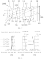
- FIG. 1 is a schematic diagram of an optical system 100 according to a first embodiment of the present application.
- the optical system 100 includes a first lens L1, a second lens L2, an aperture stop STO, a third lens L3, a fourth lens L4, a fifth lens L5, and a sixth lens L6, which are sequentially arranged from the object side to the image side along the optical axis O.
- the materials of the first lens L1, the second lens L2, the third lens L3, the fourth lens L4, the fifth lens L5, and the sixth lens L6 are referred to the above embodiments and will not be repeated.
- the first lens L1 has negative refractive power
- the second lens L2 has negative refractive power
- the third lens L3 has positive refractive power
- the fourth lens L4 has negative refractive power
- the fifth lens L5 has positive refractive power
- the sixth lens L6 has negative refractive power.
- the object side surface S1 of the first lens L1 is convex near the optical axis O
- the image side surface S2 of the first lens L1 is concave near the optical axis O
- the object side surface S3 of the second lens L2 is concave near the optical axis O
- the image side surface S4 of the second lens L2 is convex near the optical axis O
- the object side surface S5 of the third lens L3 is convex near the optical axis O
- the image side surface S6 of the third lens L3 is convex near the optical axis O.
- the object side surface S7 of the fourth lens L4 is concave near the optical axis O, and the image side surface S8 of the fourth lens L4 is concave near the optical axis O.
- the object side S9 of the fifth lens L5 is convex near the optical axis O, and the image side surface S10 of the fifth lens L5 is convex near the optical axis O.
- the object side surface S11 of the sixth lens L6 is convex near the optical axis O, and the image side surface S12 of the sixth lens L6 is concave near the optical axis O.
- the focal length F of the optical system 100 is 6.8509mm
- the aperture number FNO of the optical system 100 is 1.8
- the maximum field of view FOV of the optical system 100 is 88deg
- the total optical length TTL of the optical system 100 is 27.005mm.
- Other parameters of the optical system 100 are shown in Table 1 below.
- the components arranged along the optical axis O of the optical system 100 from the object side to the image side are shown in the order from top to bottom in Table 1.
- the surface with a smaller surface numeral is the object side surface of the lens
- the surface with a larger surface is the image side surface of the lens.
- the surface numerals 1 and 2 correspond to the object side surface S1 and image side surface S2 of the first lens, respectively.
- the Y radius in Table 1 refers to the radius of curvature of the object side surface or image side surface with the corresponding surface numeral at the optical axis O.
- the first value is the thickness of the lens at the optical axis O
- the second value is the distance from the image side surface of the lens to the next surface at the optical axis O.
- the value is the distance from the aperture stop STO to the vertex of the next surface (the vertex refers to the intersection point of the surface and the optical axis O) at the optical axis O.
- the direction from the object side surface S1 of the first lens to the image side surface of the last lens is a positive direction of the optical axis O.
- the aperture stop STO is indicated to be located on the image side of the vertex of the next surface.
- the aperture stop STO is indicated to be located on the object side of the vertex of the next surface.
- the units of the Y radius, thickness, and focal length in Table 1 are mm.
- the refractive index and Abbe number in Table 1 are obtained at a reference wavelength of 587.56nm, while the reference wavelength of the focal length is 435.83nm.
- the k in Table 2 is cone constant, and Table 2 provides the high-order coefficients A4, A6, A8, A10, A12, A14, A16, A18, and A20 that can be used for each aspherical surfaces of the first embodiment.
- a longitudinal spherical aberration diagram of the optical system 100 of the first embodiment at wavelengths of 656.27nm, 587.56nm, 546.07nm, 486.13nm, and 435.83nm is shown.
- the horizontal coordinate along X-axis represents deviation of the focus point in mm
- the vertical coordinate along Y-axis represents the normalized field of view. From (A) of FIG. 2 , the spherical aberration of the optical system 100 of the first embodiment is good, indicating that the imaging quality of the optical system 100 of this embodiment is good.
- an astigmatism diagram of the optical system 100 of the first embodiment at a wavelength of 435.83nm is shown.
- the horizontal coordinate along X-axis represents deviation of the focus point in mm
- the vertical coordinate along Y-axis represents the field of view in deg.
- T of the astigmatism diagram represents the curvature of the imaging surface IMG in the tangential direction
- S represents the curvature of the imaging surface IMG in the sagittal direction. From (B) of FIG. 2 , the astigmatism of the optical system 100 has been corrected at the wavelength.
- a distortion diagram of the optical system 100 of the first embodiment at a wavelength of 435.83nm is shown.
- the horizontal coordinate along X-axis represents the distortion
- the vertical coordinate along Y-axis represents the field of view in deg. From (C) of FIG. 2 , the distortion of the optical system 100 has been corrected at this wavelength.
- FIG. 3 is a schematic diagram of an optical system 100 according to a second embodiment of the present application.
- the optical system 100 includes a first lens L1, a second lens L2, a third lens L3, an aperture stop STO, a fourth lens L4, a fifth lens L5, and a sixth lens L6, which are sequentially arranged from the object side to the image side along the optical axis O.
- the materials of the lenses are referred to the above embodiments and will not be repeated.
- the first lens L1 has negative refractive power
- the second lens L2 has negative refractive power
- the third lens L3 has positive refractive power
- the fourth lens L4 has positive refractive power
- the fifth lens L5 has negative refractive power
- the sixth lens L6 has positive refractive power.
- the object side surface S1 of the first lens L1 is convex near the optical axis O
- the image side surface S2 of the first lens L1 is concave near the optical axis O
- the object side surface S3 of the second lens L2 is concave near the optical axis O
- the image side surface S4 of the second lens L2 is convex near the optical axis O
- the object side surface S5 of the third lens L3 is convex near the optical axis O
- the image side surface S6 of the third lens L3 is convex near the optical axis O.
- the object side surface S7 of the fourth lens L4 is convex near the optical axis O, and the image side surface S8 of the fourth lens L4 is concave near the optical axis O.
- the object side surface S9 of the fifth lens L5 is convex near the optical axis O, and the image side surface S10 of the fifth lens L5 is convex near the optical axis O;
- the object side S11 of the sixth lens L6 is convex near the optical axis O, and the image side surface S12 of the sixth lens L6 is convex near the optical axis O.
- the focal length F of the optical system 100 is 6.64mm
- the aperture number FNO of the optical system 100 is 1.83
- the maximum field of view FOV of optical system 100 is 88deg
- the total optical length TTL of the optical system 100 is 30.016mm.
- Other parameters in the second embodiment are shown in Tables 3 and 4 below, and the definitions of each parameter can be referred to the description of the previous embodiment, which will not be repeated.
- the longitudinal spherical aberration diagram, (B) astigmatism diagram, and (C) distortion diagram of FIG. 4 the longitudinal spherical aberration, the astigmatism, and the distortion of the optical system 100 of the second embodiment have been controlled, thus the optical system 100 of this embodiment has good imaging quality.
- the wavelengths corresponding to the curves in (A), (B), and (C) of FIG. 4 are referred to wavelengths corresponding to the curves in (A), (B), and (C) of FIG. 2 of the first embodiment, which will not be repeated.
- FIG. 5 is a schematic diagram of an optical system 100 according to a third embodiment of the present application.
- the optical system 100 includes a first lens L1, a second lens L2, a third lens L3, an aperture stop STO, a fourth lens L4, a fifth lens L5, and a sixth lens L6, which are sequentially arranged from the object side to the image side along the optical axis O.
- the materials of the lenses are referred to the above embodiments and will not be repeated.
- the first lens L1 has negative refractive power
- the second lens L2 has negative refractive power
- the third lens L3 has positive refractive power
- the fourth lens L4 has positive refractive power
- the fifth lens L5 has negative refractive power
- the sixth lens L6 has positive refractive power.
- the object side surface S1 of the first lens L1 is concave near the optical axis O
- the image side surface S2 of the first lens L1 is concave near the optical axis O
- the object side surface S3 of the second lens L2 is concave near the optical axis O
- the image side surface S4 of the second lens L2 is convex near the optical axis O
- the object side surface S5 of the third lens L3 is convex near the optical axis O
- the image side surface S6 of the third lens L3 is convex near the optical axis O.
- the object side surface S7 of the fourth lens L4 is convex near the optical axis O, and the image side surface S8 of the fourth lens L4 is convex near the optical axis O.
- the object side surface S9 of the fifth lens L5 is concave near the optical axis O, and the image side surface S10 of the fifth lens L5 is concave near the optical axis O.
- the object side surface S11 of the sixth lens L6 is convex near the optical axis O, and the image side surface S12 of the sixth lens L6 is convex near the optical axis O.
- the focal length F of the optical system 100 is 6.69mm
- the aperture number FNO of the optical system 100 is 1.83
- the maximum field of view FOV of the optical system 100 is 85.5deg
- the total optical length TTL of the optical system 100 is 30.003mm.
- Other parameters of the third embodiment are shown in Tables 5 and 6 below, and the definitions of each parameter can be referred to the description of the previous embodiment, which will not be repeated.
- the longitudinal spherical aberration diagram, (B) astigmatism diagram, and (C) distortion diagram of FIG. 6 have been controlled, thus the optical system 100 of this embodiment has good imaging quality.
- the wavelengths corresponding to the curves in (A), (B), and (C) of FIG. 6 are referred to wavelengths corresponding to the curves in (A), (B), and (C) of FIG. 2 of the first embodiment, which will not be repeated.
- FIG. 7 is a schematic diagram of an optical system 100 according to a fourth embodiment of the present application.
- the optical system 100 includes a first lens L1, a second lens L2, a third lens L3, an aperture stop STO, a fourth lens L4, a fifth lens L5, and a sixth lens L6, which are sequentially arranged from the object side to the image side along the optical axis O.
- the materials of the lenses are referred to the above embodiments and will not be repeated.
- the first lens L1 has negative refractive power
- the second lens L2 has negative refractive power
- the third lens L3 has positive refractive power
- the fourth lens L4 has negative refractive power
- the fifth lens L5 has positive refractive power
- the sixth lens L6 has negative refractive power.
- the object side surface S1 of the first lens L1 is convex near the optical axis O
- the image side surface S2 of the first lens L1 is concave near the optical axis O
- the object side surface S3 of the second lens L2 is concave near the optical axis O
- the image side surface S4 of the second lens L2 is convex near the optical axis O
- the object side surface S5 of the third lens L3 is convex near the optical axis O
- the image side surface S6 of the third lens L3 is convex near the optical axis O.
- the object side surface S7 of the fourth lens L4 is concave near the optical axis O, and the image side surface S8 of the fourth lens L4 is concave near the optical axis O.
- the object side surface S9 of the fifth lens L5 is convex near the optical axis O, and the image side surface S10 of the fifth lens L5 is convex near the optical axis O.
- the object side surface S11 of the sixth lens L6 is convex near the optical axis O, while the image side surface S12 of the sixth lens L6 is concave near the optical axis O.
- the focal length F of the optical system 100 is 6.77mm
- the aperture number FNO of the optical system 100 is 1.8
- the maximum field of view FOV of the optical system 100 is 88.05deg
- the total optical length TTL of the optical system 100 is 26.868mm.
- Other parameters in the fourth embodiment are shown in Tables 7 and 8 below, and the definitions of each parameter can be referred to the description of the previous embodiment, which will not be repeated.
- the longitudinal spherical aberration diagram, (B) astigmatism diagram, and (C) distortion diagram of FIG. 8 the longitudinal spherical aberration, the astigmatism, and the distortion of the optical system 100 of the fourth embodiment have been controlled, thus the optical system 100 of this embodiment has good imaging quality.
- the wavelengths corresponding to the curves in (A), (B), and (C) of FIG. 8 are referred to wavelengths corresponding to the curves in (A), (B), and (C) of FIG. 2 of the first embodiment, which will not be repeated.
- FIG. 9 is a schematic diagram of an optical system 100 according to a fifth embodiment of the present application.
- the optical system 100 includes a first lens L1, a second lens L2, a third lens L3, an aperture stop STO, a fourth lens L4, a fifth lens L5, and a sixth lens L6, which are sequentially arranged from the object side to the image side along the optical axis O.
- the materials of the lenses are referred to the above embodiments and will not be repeated.
- the first lens L1 has negative refractive power
- the second lens L2 has negative refractive power
- the third lens L3 has positive refractive power
- the fourth lens L4 has negative refractive power
- the fifth lens L5 has positive refractive power
- the sixth lens L6 has negative refractive power.
- the object side surface S1 of the first lens L1 is concave near the optical axis O
- the image side surface S2 of the first lens L1 is concave near the optical axis O
- the object side surface S3 of the second lens L2 is concave near the optical axis O
- the image side surface S4 of the second lens L2 is convex near the optical axis O
- the object side surface S5 of the third lens L3 is convex near the optical axis O
- the image side surface S6 of the third lens L3 is convex near the optical axis O.
- the object side surface S7 of the fourth lens L4 is concave near the optical axis O, and the image side surface S8 of the fourth lens L4 is concave near the optical axis O.
- the object side surface S9 of the fifth lens L5 is convex near the optical axis O, and the image side surface S10 of the fifth lens L5 is convex near the optical axis O.
- the object side surface S11 of the sixth lens L6 is convex near the optical axis O, and the image side surface S12 of the sixth lens L6 is concave near the optical axis O.
- the focal length F of the optical system 100 is 6.79mm
- the aperture number FNO of the optical system 100 is 1.83
- the maximum field of view FOV of the optical system 100 is 89deg
- the total optical length TTL of the optical system 100 is 26.9mm.
- Other parameters in the fifth embodiment are shown in Tables 9 and 10 below, and the definitions of each parameter can be referred to the description of the previous embodiment, which will not be repeated.
- a longitudinal spherical aberration diagram of the optical system 100 of the fifth embodiment at wavelengths of 656.27nm, 587.56nm, 546.07nm, 486.13nm, and 435.83nm is shown.
- the horizontal coordinate along X-axis represents deviation of the focus point in mm
- the vertical coordinate along Y-axis represents the normalized field of view. From (A) of FIG. 10 , the spherical aberration of the optical system 100 of the fifth embodiment is good, indicating that the imaging quality of the optical system 100 of this embodiment is good.
- an astigmatism diagram of the optical system 100 of the fifth embodiment at a wavelength of 435.83nm is shown.
- the horizontal coordinate along X-axis represents deviation of the focus point in mm
- the vertical coordinate along Y-axis represents the image height in mm.
- T of the astigmatism diagram represents the curvature of the imaging surface IMG in the tangential direction
- S represents the curvature of the imaging surface IMG in the sagittal direction. From (B) of FIG. 10 , the astigmatism of the optical system 100 has been corrected at the wavelength.
- a distortion diagram of the optical system 100 of the fifth embodiment at a wavelength of 435.83nm is shown.
- the horizontal coordinate along X-axis represents the distortion
- the vertical coordinate along Y-axis represents the field of view in deg. From (C) of FIG. 10 , the distortion of the optical system 100 has been corrected at this wavelength.
- FIG. 11 is a schematic diagram of an optical system 100 according to a sixth embodiment of the present application.
- the optical system 100 includes a first lens L1, a second lens L2, a third lens L3, an aperture stop STO, a fourth lens L4, a fifth lens L5, and a sixth lens L6, which are sequentially arranged from the object side to the image side along the optical axis O.
- the materials of the lenses are referred to the above embodiments and will not be repeated.
- the first lens L1 has negative refractive power
- the second lens L2 has negative refractive power
- the third lens L3 has positive refractive power
- the fourth lens L4 has negative refractive power
- the fifth lens L5 has positive refractive power
- the sixth lens L6 has positive refractive power.
- the object side surface S1 of the first lens L1 is convex near the optical axis O
- the image side surface S2 of the first lens L1 is concave near the optical axis O
- the object side surface S3 of the second lens L2 is concave near the optical axis O
- the image side surface S4 of the second lens L2 is convex near the optical axis O
- the object side surface S5 of the third lens L3 is convex near the optical axis O
- the image side surface S6 of the third lens L3 is convex near the optical axis O.
- the object side surface S7 of the fourth lens L4 is convex near the optical axis O, and the image side surface S8 of the fourth lens L4 is concave near the optical axis O.
- the object side surface S9 of the fifth lens L5 is convex near the optical axis O, and the image side surface S10 of the fifth lens L5 is convex near the optical axis O.
- the object side surface S11 of the sixth lens L6 is convex near the optical axis O, and the image side surface S12 of the sixth lens L6 is convex near the optical axis O.
- the focal length F of the optical system 100 is 6.298mm
- the aperture number FNO of the optical system 100 is 1.83
- the maximum field of view FOV of the optical system 100 is 89.72deg
- the total optical length TTL of the optical system 100 is 30mm.
- Other parameters in the sixth embodiment are shown in Tables 11 and 12 below, and the definitions of each parameter can be referred to the description of the previous embodiment, which will not be repeated..
- the longitudinal spherical aberration diagram, (B) astigmatism diagram, and (C) distortion diagram of FIG. 12 have been controlled, thus the optical system 100 of this embodiment has good imaging quality.
- the wavelengths corresponding to the curves in (A), (B), and (C) of FIG. 12 are referred to wavelengths corresponding to the curves in (A), (B), and (C) of FIG. 10 of the fifth embodiment, which will not be repeated.
- Table 13 summarizes the ratios of various relational expressions in the first to sixth embodiments of the present application.
- Table 13 Relational expression /embodiment First embodiment Second embodiment Third embodiment Fourth embodiment Fifth embodiment
- Sixth embodiment 1.2 ⁇ IMGH/EPD ⁇ 1.4 1.252 1.317 1.341 1.255 1.285 1.381 0.89 ⁇ CT2/SD3 ⁇ 1.3 1.187 0.922 0.625 1.013 0.896 1.295 7 ⁇
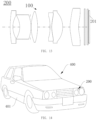
- the present application further discloses a camera module 200.
- the camera module 200 includes an image sensor 201 and an optical system 100 mentioned in any one of the first to sixth embodiments.
- the image sensor 201 is located on the image side of the optical system 100.
- the optical system 100 receives the light signal of an object and project the light signal onto the image sensor 201.
- the image sensor 201 converts the light signal corresponding to the object into an image signal.
- the camera module 200 having the optical system 100 may have large aperture and high imaging quality while maintaining a lightweight and compact design.
- the present application further discloses a terminal device 400.
- the terminal device 400 includes a fixing member and a camera module 200 mentioned in the second aspect.
- the fixing member may be a housing 401.
- the camera module 200 is located on the housing 401.
- the terminal device 400 may be, but is not limited to, a mobile phone, a tablet computer, a laptop, a smartwatch, a monitor, a driving record system, or a vehicle backup camera.
- the terminal device 400 having the camera module 200 may have all characteristics of the optical system 100, that is, the terminal device 400 may have large aperture and high imaging quality while maintaining a lightweight and compact design.
Landscapes
- Physics & Mathematics (AREA)
- General Physics & Mathematics (AREA)
- Optics & Photonics (AREA)
- Lenses (AREA)
Applications Claiming Priority (1)
| Application Number | Priority Date | Filing Date | Title |
|---|---|---|---|
| CN202311146007.XA CN117148545A (zh) | 2023-09-06 | 2023-09-06 | 光学镜头、摄像模组及终端设备 |
Publications (2)
| Publication Number | Publication Date |
|---|---|
| EP4455754A2 true EP4455754A2 (fr) | 2024-10-30 |
| EP4455754A3 EP4455754A3 (fr) | 2025-03-19 |
Family
ID=88909693
Family Applications (1)
| Application Number | Title | Priority Date | Filing Date |
|---|---|---|---|
| EP24194988.2A Pending EP4455754A3 (fr) | 2023-09-06 | 2024-08-16 | Système optique, module de caméra et dispositif terminal |
Country Status (3)
| Country | Link |
|---|---|
| US (1) | US20250076612A1 (fr) |
| EP (1) | EP4455754A3 (fr) |
| CN (1) | CN117148545A (fr) |
Families Citing this family (1)
| Publication number | Priority date | Publication date | Assignee | Title |
|---|---|---|---|---|
| CN121028357B (zh) * | 2025-10-31 | 2026-01-27 | 高视科技(苏州)股份有限公司 | 一种显微筒镜及显微系统 |
Family Cites Families (3)
| Publication number | Priority date | Publication date | Assignee | Title |
|---|---|---|---|---|
| TWI586999B (zh) * | 2015-10-23 | 2017-06-11 | 大立光電股份有限公司 | 影像擷取透鏡組、取像裝置及電子裝置 |
| CN110286474B (zh) * | 2019-07-24 | 2024-04-19 | 浙江舜宇光学有限公司 | 光学成像系统 |
| WO2021221207A1 (fr) * | 2020-04-29 | 2021-11-04 | 엘지전자 주식회사 | Lentille d'imagerie et module de caméra et véhicule la comprenant |
-
2023
- 2023-09-06 CN CN202311146007.XA patent/CN117148545A/zh active Pending
-
2024
- 2024-07-25 US US18/783,449 patent/US20250076612A1/en active Pending
- 2024-08-16 EP EP24194988.2A patent/EP4455754A3/fr active Pending
Also Published As
| Publication number | Publication date |
|---|---|
| EP4455754A3 (fr) | 2025-03-19 |
| US20250076612A1 (en) | 2025-03-06 |
| CN117148545A (zh) | 2023-12-01 |
Similar Documents
| Publication | Publication Date | Title |
|---|---|---|
| CN102789041B (zh) | 光学影像镜头 | |
| US12216248B2 (en) | Optical imaging lens assembly | |
| CN112327458B (zh) | 光学系统、摄像模组及电子设备 | |
| CN113625423A (zh) | 一种成像系统、摄像头模组及电子设备 | |
| CN102566009A (zh) | 广视角光学镜组 | |
| CN113376810B (zh) | 光学系统、取像模组及电子设备 | |
| CN212111953U (zh) | 光学成像镜头 | |
| EP4478106B1 (fr) | Lentille optique, module d'image et dispositif électronique | |
| CN112711127B (zh) | 一种成像系统、镜头模组及电子设备 | |
| EP4556983A2 (fr) | Lentille optique, module d'image et dispositif terminal | |
| CN113866941A (zh) | 光学系统、摄像模组及电子设备 | |
| CN113900226B (zh) | 光学系统、取像模组及电子设备 | |
| CN113625430B (zh) | 光学系统、取像模组、电子设备及载具 | |
| CN112987256B (zh) | 光学系统、摄像模组及电子设备 | |
| CN111367051A (zh) | 光学成像系统、镜头及电子设备 | |
| CN113900235A (zh) | 光学系统、取像模组、电子设备及载具 | |
| EP4455754A2 (fr) | Système optique, module de caméra et dispositif terminal | |
| CN109991721B (zh) | 光学透镜组 | |
| CN113433662B (zh) | 成像系统、镜头模组、电子设备及载具 | |
| CN214474190U (zh) | 光学系统、摄像模组及电子设备 | |
| CN113156612B (zh) | 光学系统、取像模组及电子设备 | |
| CN112835185B (zh) | 光学系统、摄像模组、电子设备及汽车 | |
| CN212905677U (zh) | 摄像镜头组 | |
| CN102122056A (zh) | 成像光学镜头 | |
| CN211123453U (zh) | 光学成像系统、取像装置及电子设备 |
Legal Events
| Date | Code | Title | Description |
|---|---|---|---|
| PUAI | Public reference made under article 153(3) epc to a published international application that has entered the european phase |
Free format text: ORIGINAL CODE: 0009012 |
|
| STAA | Information on the status of an ep patent application or granted ep patent |
Free format text: STATUS: THE APPLICATION HAS BEEN PUBLISHED |
|
| AK | Designated contracting states |
Kind code of ref document: A2 Designated state(s): AL AT BE BG CH CY CZ DE DK EE ES FI FR GB GR HR HU IE IS IT LI LT LU LV MC ME MK MT NL NO PL PT RO RS SE SI SK SM TR |
|
| REG | Reference to a national code |
Ref country code: DE Ref legal event code: R079 Free format text: PREVIOUS MAIN CLASS: G02B0009620000 Ipc: G02B0013000000 |
|
| PUAL | Search report despatched |
Free format text: ORIGINAL CODE: 0009013 |
|
| AK | Designated contracting states |
Kind code of ref document: A3 Designated state(s): AL AT BE BG CH CY CZ DE DK EE ES FI FR GB GR HR HU IE IS IT LI LT LU LV MC ME MK MT NL NO PL PT RO RS SE SI SK SM TR |
|
| RIC1 | Information provided on ipc code assigned before grant |
Ipc: G02B 9/62 20060101ALN20250207BHEP Ipc: G02B 13/04 20060101ALI20250207BHEP Ipc: G02B 13/18 20060101ALI20250207BHEP Ipc: G02B 13/00 20060101AFI20250207BHEP |
|
| STAA | Information on the status of an ep patent application or granted ep patent |
Free format text: STATUS: REQUEST FOR EXAMINATION WAS MADE |
|
| 17P | Request for examination filed |
Effective date: 20250813 |
|
| RAP3 | Party data changed (applicant data changed or rights of an application transferred) |
Owner name: JIANGXI OFILM OPTICAL CO., LTD. |
|
| GRAP | Despatch of communication of intention to grant a patent |
Free format text: ORIGINAL CODE: EPIDOSNIGR1 |
|
| STAA | Information on the status of an ep patent application or granted ep patent |
Free format text: STATUS: GRANT OF PATENT IS INTENDED |