EP4455809A1 - Commande d'une machine-outil multibroche - Google Patents
Commande d'une machine-outil multibroche Download PDFInfo
- Publication number
- EP4455809A1 EP4455809A1 EP23169374.8A EP23169374A EP4455809A1 EP 4455809 A1 EP4455809 A1 EP 4455809A1 EP 23169374 A EP23169374 A EP 23169374A EP 4455809 A1 EP4455809 A1 EP 4455809A1
- Authority
- EP
- European Patent Office
- Prior art keywords
- tool
- spindle
- path
- machine axes
- machine
- Prior art date
- Legal status (The legal status is an assumption and is not a legal conclusion. Google has not performed a legal analysis and makes no representation as to the accuracy of the status listed.)
- Pending
Links
Images


Classifications
-
- G—PHYSICS
- G05—CONTROLLING; REGULATING
- G05B—CONTROL OR REGULATING SYSTEMS IN GENERAL; FUNCTIONAL ELEMENTS OF SUCH SYSTEMS; MONITORING OR TESTING ARRANGEMENTS FOR SUCH SYSTEMS OR ELEMENTS
- G05B19/00—Program-control systems
- G05B19/02—Program-control systems electric
- G05B19/18—Numerical control [NC], i.e. automatically operating machines, in particular machine tools, e.g. in a manufacturing environment, so as to execute positioning, movement or co-ordinated operations by means of program data in numerical form
- G05B19/404—Numerical control [NC], i.e. automatically operating machines, in particular machine tools, e.g. in a manufacturing environment, so as to execute positioning, movement or co-ordinated operations by means of program data in numerical form characterised by control arrangements for compensation, e.g. for backlash, overshoot, tool offset, tool wear, temperature, machine construction errors, load, inertia
-
- G—PHYSICS
- G05—CONTROLLING; REGULATING
- G05B—CONTROL OR REGULATING SYSTEMS IN GENERAL; FUNCTIONAL ELEMENTS OF SUCH SYSTEMS; MONITORING OR TESTING ARRANGEMENTS FOR SUCH SYSTEMS OR ELEMENTS
- G05B19/00—Program-control systems
- G05B19/02—Program-control systems electric
- G05B19/18—Numerical control [NC], i.e. automatically operating machines, in particular machine tools, e.g. in a manufacturing environment, so as to execute positioning, movement or co-ordinated operations by means of program data in numerical form
- G05B19/19—Numerical control [NC], i.e. automatically operating machines, in particular machine tools, e.g. in a manufacturing environment, so as to execute positioning, movement or co-ordinated operations by means of program data in numerical form characterised by positioning or contouring control systems, e.g. to control position from one programmed point to another or to control movement along a programmed continuous path
-
- B—PERFORMING OPERATIONS; TRANSPORTING
- B23—MACHINE TOOLS; METAL-WORKING NOT OTHERWISE PROVIDED FOR
- B23Q—DETAILS, COMPONENTS, OR ACCESSORIES FOR MACHINE TOOLS, e.g. ARRANGEMENTS FOR COPYING OR CONTROLLING; MACHINE TOOLS IN GENERAL CHARACTERISED BY THE CONSTRUCTION OF PARTICULAR DETAILS OR COMPONENTS; COMBINATIONS OR ASSOCIATIONS OF METAL-WORKING MACHINES, NOT DIRECTED TO A PARTICULAR RESULT
- B23Q39/00—Metal-working machines incorporating a plurality of sub-assemblies, each capable of performing a metal-working operation
- B23Q39/04—Metal-working machines incorporating a plurality of sub-assemblies, each capable of performing a metal-working operation the sub-assemblies being arranged to operate simultaneously at different stations, e.g. with an annular work-table moved in steps
-
- G—PHYSICS
- G05—CONTROLLING; REGULATING
- G05B—CONTROL OR REGULATING SYSTEMS IN GENERAL; FUNCTIONAL ELEMENTS OF SUCH SYSTEMS; MONITORING OR TESTING ARRANGEMENTS FOR SUCH SYSTEMS OR ELEMENTS
- G05B19/00—Program-control systems
- G05B19/02—Program-control systems electric
- G05B19/18—Numerical control [NC], i.e. automatically operating machines, in particular machine tools, e.g. in a manufacturing environment, so as to execute positioning, movement or co-ordinated operations by means of program data in numerical form
- G05B19/182—Numerical control [NC], i.e. automatically operating machines, in particular machine tools, e.g. in a manufacturing environment, so as to execute positioning, movement or co-ordinated operations by means of program data in numerical form characterised by the machine tool function, e.g. thread cutting, cam making, tool direction control
-
- G—PHYSICS
- G05—CONTROLLING; REGULATING
- G05B—CONTROL OR REGULATING SYSTEMS IN GENERAL; FUNCTIONAL ELEMENTS OF SUCH SYSTEMS; MONITORING OR TESTING ARRANGEMENTS FOR SUCH SYSTEMS OR ELEMENTS
- G05B19/00—Program-control systems
- G05B19/02—Program-control systems electric
- G05B19/18—Numerical control [NC], i.e. automatically operating machines, in particular machine tools, e.g. in a manufacturing environment, so as to execute positioning, movement or co-ordinated operations by means of program data in numerical form
- G05B19/408—Numerical control [NC], i.e. automatically operating machines, in particular machine tools, e.g. in a manufacturing environment, so as to execute positioning, movement or co-ordinated operations by means of program data in numerical form characterised by data handling or data format, e.g. reading, buffering or conversion of data
-
- G—PHYSICS
- G05—CONTROLLING; REGULATING
- G05B—CONTROL OR REGULATING SYSTEMS IN GENERAL; FUNCTIONAL ELEMENTS OF SUCH SYSTEMS; MONITORING OR TESTING ARRANGEMENTS FOR SUCH SYSTEMS OR ELEMENTS
- G05B2219/00—Program-control systems
- G05B2219/30—Nc systems
- G05B2219/35—Nc in input of data, input till input file format
- G05B2219/35349—Display part, programmed locus and tool path, traject, dynamic locus
-
- G—PHYSICS
- G05—CONTROLLING; REGULATING
- G05B—CONTROL OR REGULATING SYSTEMS IN GENERAL; FUNCTIONAL ELEMENTS OF SUCH SYSTEMS; MONITORING OR TESTING ARRANGEMENTS FOR SUCH SYSTEMS OR ELEMENTS
- G05B2219/00—Program-control systems
- G05B2219/30—Nc systems
- G05B2219/49—Nc machine tool, till multiple
- G05B2219/49297—Spindle identification in multispindle station
-
- G—PHYSICS
- G05—CONTROLLING; REGULATING
- G05B—CONTROL OR REGULATING SYSTEMS IN GENERAL; FUNCTIONAL ELEMENTS OF SUCH SYSTEMS; MONITORING OR TESTING ARRANGEMENTS FOR SUCH SYSTEMS OR ELEMENTS
- G05B2219/00—Program-control systems
- G05B2219/30—Nc systems
- G05B2219/50—Machine tool, machine tool null till machine tool work handling
- G05B2219/50008—Multiple, multi tool head, parallel machining
-
- G—PHYSICS
- G05—CONTROLLING; REGULATING
- G05B—CONTROL OR REGULATING SYSTEMS IN GENERAL; FUNCTIONAL ELEMENTS OF SUCH SYSTEMS; MONITORING OR TESTING ARRANGEMENTS FOR SUCH SYSTEMS OR ELEMENTS
- G05B2219/00—Program-control systems
- G05B2219/30—Nc systems
- G05B2219/50—Machine tool, machine tool null till machine tool work handling
- G05B2219/50014—Several, multi workpieces
-
- G—PHYSICS
- G05—CONTROLLING; REGULATING
- G05B—CONTROL OR REGULATING SYSTEMS IN GENERAL; FUNCTIONAL ELEMENTS OF SUCH SYSTEMS; MONITORING OR TESTING ARRANGEMENTS FOR SUCH SYSTEMS OR ELEMENTS
- G05B2219/00—Program-control systems
- G05B2219/30—Nc systems
- G05B2219/50—Machine tool, machine tool null till machine tool work handling
- G05B2219/50235—Select tools, slides, spindles to work synchronized, independent
Definitions
- the present invention relates to a method for computer-aided numerical control of a multi-spindle machine tool, which has a first tool spindle equipped with a first tool and a second tool spindle that can be controlled independently of the first tool spindle and equipped with a second tool.
- the invention further relates to a multi-spindle machine tool, having a first tool spindle that can be equipped with a first tool and a second tool spindle that can be controlled independently of the first tool spindle and equipped with a second tool.
- the invention also relates to a computer program and a computer-readable storage medium.
- multi-spindle machine tools also known as multi-spindle machines. These have two or more tool spindles for the corresponding machining of two or more workpieces. This means that two or more machining operations and thus the motion control and spindle control must take place simultaneously, i.e. synchronously with one another.
- the use of several synchronous machining units on one machine can be applied to a wide variety of technologies, for example for milling, turning, grinding, and so on.
- Multi-spindle machine tools with exactly two tool spindles are also known as double-spindle machine tools or double-spindle machines.
- two workpieces can be machined simultaneously with two tools on double spindle machines, so that at the end of the machining process there are two nominally identical workpieces.
- the machining of the two workpieces takes place synchronously.
- the output on a double spindle machine is twice as high as that of a single spindle machine.
- a double spindle machine can also be operated, to produce only one workpiece, the second spindle is then not active.
- the two tool spindles are mechanically rigidly connected to one another.
- the spindle assembly is then moved by the common axes, for example the X, Y and Z axes.
- a more complex concept provides for independent Z axes for each of the two tool spindles. This allows the tool spindles to be positioned differently in the Z direction.
- An even more complex concept makes it possible to move the tool spindles and thus the tools in all three axis directions by using compensating axes that are redundantly installed on the main axes, but only for comparatively short travel ranges.
- a particularly high level of precision can be achieved by so-called true multi-spindle machine tools, i.e. multi-spindle machine tools with two or more independent tool spindles that can be controlled and thus moved independently of one another.
- the two tool spindles are then each equipped with their own X, Y and Z axes, for example.
- additional linear axes and/or rotation axes can be provided instead or in addition, each of which is independent for both tool spindles.
- the tool spindles are then operated and controlled via one and the same CNC control, for example Each tool spindle has its own machining channel.
- the individual axes of the tool spindles can partially use the same guide rail.
- One advantage of true multi-spindle machine tools is that the different tool spindles can be equipped with tools that are nominally identical but whose dimensions differ from one another, for example due to different levels of wear, to produce nominally identical workpieces.
- the independent control of the different tool spindles can compensate for the different dimensions.
- a mechanical offset between the two tool spindles is desirable to design a mechanical offset between the two tool spindles as small as possible, for example less than 1 m or in the range of 500 mm.
- the movable stands on which the tool spindles are mounted or other movable components would have to be very close to each other, for example a few millimeters. There would therefore be a potential risk of collision. This would exist in particular if the tool spindles were controlled differently to compensate for different tool dimensions, as explained above.
- the invention is based on the idea of synchronizing the same part program in two machining channels in order to machine a first workpiece using a first tool, with which a first tool spindle is equipped, and a second workpiece using a second tool, with which a second tool spindle is equipped.
- the tool spindles are moved differently despite the identical part program, so that both tool spindles are forced to be synchronized.
- a method for computer-aided numerical control (CNC) of a multi-spindle machine tool is specified.
- the multi-spindle machine tool has a first tool spindle equipped with a first tool and a second tool spindle equipped with a second tool.
- the second tool spindle can be controlled independently of the first tool spindle.
- a first workpiece is machined using the first tool by executing a predetermined part program in a first machining channel, in particular by means of the control device.
- a second workpiece is machined using the second tool by executing the part program in a second machining channel synchronized with the first machining channel, in particular by means of the control device.
- the execution of the part program in the first machining channel includes controlling first machine axes of the multi-spindle machine tool for guiding the first tool spindle according to a first tool path.
- the execution of the part program in the second machining channel includes a control of second machine axes of the multi-spindle machine tool for guiding the second tool spindle according to a second tool path.
- the first tool spindle is guided according to the first tool path and the second tool spindle is guided according to the second tool path.
- a machining result of the first workpiece at one end of the first tool path is equal to a machining result of the second workpiece at one end of the second tool path.
- the first machine axes and the second machine axes are controlled in such a way that a time difference between the first tool reaching the end of the first tool path and the second tool reaching the end of the second tool path is less than or equal to a predetermined limit value.
- the first tool spindle can be guided by appropriate control and movement of the first machine axes and the second tool spindle by appropriate control and movement of the second machine axes.
- the first machine axes or the second machine axes can each contain one or more linear or translational axes, for example an x-axis, a y-axis and a z-axis.
- the first machine axes or the second machine axes can contain respective rotation axes.
- the tool spindles can be controlled independently of each other. This can be understood in particular to mean that the first machine axes can be controlled and moved independently of the second machine axes. It is therefore possible in principle to use the first tool spindle and the second tool spindle to process different part programs.
- the fact that the part program is processed synchronously in the first and second processing channels can in particular be understood in such a way that the processing takes place simultaneously or in parallel and accordingly the control of the first machine axes is also synchronized with the control of the second machine axes, so that the movement of the first tool spindle is also synchronized with the movement of the second tool spindle, i.e. in particular simultaneously.
- the synchronized processing of the part program in the two machining channels and the resulting synchronized movement of the first tool spindle and the second tool spindle can be understood in such a way that the movement of the first tool spindle along the first tool path begins and ends simultaneously with the movement of the second tool spindle along the second tool path up to a predetermined tolerance value.
- further intermediate positions on the first and second tool paths can optionally be specified, which are reached simultaneously according to the synchronized processing and the synchronized movement of the tool spindles up to a predetermined tolerance value.
- first tool dimensions of the first tool can be obtained, in particular by a control device of the multi-spindle machine tool, which is set up for CNC control of the first tool spindle and the second tool spindle.
- second tool dimensions of the second tool can be obtained, in particular by the control device. The first tool dimensions differ from the second tool dimensions.
- a speed difference between a first average path speed of the first tool path and a second average path speed of the second tool path is set by the respective control of the first machine axes and the second machine axes depending on the first tool dimensions and the second tool dimensions, in particular automatically, for example by means of the control device depending on the part program.
- the first tool is nominally identical to the second tool.
- the different tool dimensions result, for example, from different degrees of wear of the first tool and the second tool.
- the target dimensions for the first workpiece and the second workpiece are also identical.
- first tools or second tools are used.
- the type of tool dimensions can also differ depending on the technology.
- the first and second tools are defined by respective target dimensions, possibly including corresponding tolerance ranges, for one or more dimensions, for example length dimensions or radii and so on.
- the first tool dimensions or the second tool dimensions correspond to the actual dimensions according to these target dimensions and therefore generally differ from one another for the first and second tools.
- the first and second tool dimensions can be determined by conventional measurements, for example manual or automatic measurements, before carrying out the method according to the invention and provided to the control device It is also possible that in some embodiments of the method according to the invention the first and/or the second tool dimensions are determined in a method step of the method according to the invention, in particular automatically, for example by means of the multi-spindle machine tool itself.
- first tool dimensions differ from the second tool dimensions can be understood in particular in such a way that the first tool dimensions contain one or more first actual values for the first tool and the second tool dimensions contain one or more actual values for the second tool, wherein at least one of the first actual values differs from a corresponding one of the second actual values.
- the first tool path and the second tool path are given by the part program, i.e. in particular predetermined target movements or target dimensions of the part program, in combination with the first tool dimensions and the second tool dimensions.
- first tool dimensions differ from the second tool dimensions
- an adjustment of the average path speeds of the first tool path and the second tool path is provided in corresponding embodiments for the synchronized movement of the tool spindles.
- the exact relationship between the speed difference and the difference in the first and second tool dimensions depends on the design of the tools and on the machining result for the workpieces. However, if the respective machining result is specified, in particular by the part program, and the differences in the tool dimensions are known, geometric considerations can always be used to calculate how the average speeds between the two tool paths must differ from one another so that the synchronized movement is achieved.
- the speed difference between the average path speed of the first tool path and the average path speed of the second tool path can be achieved in different ways.
- the tool spindles can be moved continuously, with the average path speed of one of the paths being lower than that of the other path. It is also possible, for example, for one of the tool spindles to be moved continuously, whereas the other tool spindle is only moved continuously in parts, i.e. it is stopped once or several times along the corresponding tool path in order to reduce the corresponding path speed on average.
- first tool path and the second tool path do not necessarily correspond to a complete machining step for machining the workpieces, but may also correspond only to a part of such a machining step.
- the speed difference can also be adjusted in different ways, in particular through the control device, for example directly or indirectly.
- the speed difference can be calculated from the target specifications of the part program and the difference in the tool dimensions and the corresponding dynamic parameters of the first and second machine axes, i.e. in particular their axis speeds and/or axis accelerations and/or axis jerks, can be selected by the control device depending on the speed difference calculated in this way.
- the dynamic parameters of the machine axes can be calculated directly from the difference between the tool dimensions and the target specifications of the part program, so that the synchronized movement of the tool spindles takes place.
- the speed difference may depend on the actual or target values for the tool dimensions in addition to the difference in the tool dimensions.
- a difference between the processing times of the first workpiece and the second workpiece can be minimized or brought below a predetermined tolerance value. In this way, it can be ensured that the current deviation of the individual axis positions or tool spindle positions remain at least approximately constant while the first and second workpieces are being processed. In this way, the risk of collisions between the first tool spindle and the second tool spindle or between frame elements, stands or other moving components is reduced. Consequently, a smaller working space of the multi-spindle machine tool can be achieved.
- the speed difference is not explicitly included in the part program, so it does not have to be explicitly programmed by a user. Instead, the control device can calculate or set it based on the difference between the tool dimensions.
- a forced synchronization of the two machining channels is achieved by forcibly slowing down the shorter path due to the deviations in the tool dimensions in order to adapt to the longer path.
- the speed difference is calculated depending on the first tool dimensions and the second tool dimensions, in particular by means of the control device.
- the speed difference is calculated in particular depending on the first tool dimensions and the second tool dimensions as well as target specifications according to the part program.
- Respective axis dynamics variables for the first machine axes and for the second machine axes are calculated depending on the speed difference.
- the speed difference is set by controlling the first machine axes and the second machine axes in accordance with the calculated respective axis dynamics variables.
- the axis dynamics variables therefore include in particular first axis dynamics variables for the first machine axes and second axis dynamics variables for the second machine axes.
- the respective axis dynamics variables can include, for example, respective axis speeds of the first machine axes or the second machine axes, respective axis accelerations of the first machine axes or the second machine axes and/or respective axis jerks of the first machine axes or the second machine axes and/or respective axis snaps of the first machine axes or the second machine axes.
- the snap is the time derivative of the jerk, i.e. the fourth time derivative of the location. If necessary, even higher derivatives of the location can also be taken into account.
- respective axis dynamics variables of the first machine axes and the second machine axes are calculated depending on the first tool dimensions and the second tool dimensions, in particular by means of the control device.
- the speed difference is set by controlling the first machine axes and the second machine axes in accordance with the calculated respective axis dynamics variables.
- the speed difference is not calculated explicitly, but the setting of the speed difference is done indirectly by setting the respective axis dynamics variables.
- the calculation of the respective axis dynamics variables can be carried out in particular depending on the first tool dimensions and the second tool dimensions as well as depending on the target specifications according to the part program.
- the respective axis dynamics variables contain respective axis speeds of the first machine axes and the second machine axes.
- first axis dynamics quantities contain first axis velocities of the first machine axes and the second axis dynamics quantities contain second axis velocities of the second machine axes.
- the respective axis speeds can, for example, be constant or piecewise constant speeds during the respective tool path, or they can be corresponding target speeds for the corresponding machine axes.
- the respective axis speeds can, for example, be achieved by the maximum permissible axis accelerations, or the axis accelerations can also be specified, or a range for the axis accelerations can be specified.
- the speed difference can be easily adjusted.
- the respective axis dynamics variables contain respective axis accelerations of the first machine axes and the second machine axes.
- the first axis dynamics variables contain respective axis accelerations of the first machine axes and the second axis dynamics variables of the second machine axes contain respective axis accelerations of the second machine axes.
- first axis dynamics quantities contain first axis accelerations of the first machine axes and the second axis dynamics quantities contain second axis accelerations of the second machine axes.
- the respective axis accelerations can, for example, be constant or piecewise constant accelerations during the respective tool path, or they can be corresponding target accelerations for the corresponding machine axes.
- the respective axis accelerations can, for example, be achieved by the maximum permissible axis jerks, or the axis jerks can also be specified, or a range for the axis jerks can be specified.
- the respective axis dynamics variables contain respective axis jerks of the first machine axes and the second machine axes.
- the first axis dynamics variables contain respective axis jerks of the first machine axes and the second axis dynamics variables of the second machine axes contain respective axis jerks of the second machine axes.
- first axis dynamics quantities contain first axis jerks of the first machine axes and the second axis dynamics quantities contain second axis jerks of the second machine axes.
- the speed difference is set by determining at least one first stop interval depending on the first tool dimensions and the second tool dimensions and stopping the first tool spindle along the first tool path during the at least one first stop interval.
- at least one second stop interval is determined depending on the difference between the first tool dimensions and the second tool dimensions, in particular by means of the control device, and the second tool spindle is stopped along the second tool path during the at least one second stop interval.
- the movement of the first tool spindle is artificially slowed down by the at least one first stop interval in order to achieve synchronicity between the two processing channels, or the movement of the second tool spindle is artificially slowed down by the at least one second stop interval in order to achieve synchronicity.
- the speed difference then results from the at least one first stop interval or from the at least one second stop interval.
- the at least one first stop interval is determined and the first tool spindle is stopped accordingly, or the at least one second stop interval is determined and the second tool spindle is stopped accordingly as described.
- Which of the two cases occurs depends on how the tool dimensions differ and how the target specifications are structured according to the part program. In particular, the tool spindle whose path length is shorter is artificially slowed down.
- a stop interval can be understood as a period of time during which all corresponding machine axes are stopped, i.e. stand still. During the at least one first stop interval, the first machine axes stand still, and during the at least one second stop interval, the second machine axes stand still.
- the at least one first stop interval can include two or more first stop intervals, in particular three or more first stop intervals.
- the at least one second stop interval can include two or more second stop intervals, in particular three or more second stop intervals. The more stop intervals are provided, the smaller the maximum position deviation between the two tools remains.
- the respective axis dynamics variables, in particular the respective axis speeds, of the first machine axes or the second machine axes outside the corresponding stop intervals can be selected to be substantially equal.
- an acceleration difference between a first path acceleration of the first tool path and a second path acceleration of the second tool path is set depending on the difference between the first tool dimensions and the second tool dimensions, in particular by means of the control device by controlling the first machine axes and the second machine axes.
- a jerk difference between a first path jerk of the first tool path and a second path jerk of the second tool path is set depending on the difference between the first tool dimensions and the second tool dimensions, in particular by means of the control device by controlling the first machine axes and the second machine axes.
- identical target dimensions are specified for the first workpiece and the second workpiece and the part program is specified according to the target dimensions.
- all target dimensions for the first workpiece are equal to the corresponding target dimensions for the second workpiece.
- the first workpiece manufactured is therefore nominally identical to the second workpiece manufactured.
- the part program is specified, in particular programmed, in such a way that the identical target dimensions result.
- identical target dimensions can also be assumed for the first and second tools.
- the first tool dimensions and the second tool dimensions are respectively actual dimensions and target dimensions for the first tool and are identical to target dimensions for the second tool.
- the difference between the first dimensions and the second dimensions results from wear or deterioration of the first or second tool, respectively.
- the first tool dimensions are measured by means of a measuring device of the multi-spindle machine tool and/or the second tool dimensions are measured by means of the measuring device or a further measuring device of the multi-spindle machine tool.
- the measured first and/or second tool dimensions can be transmitted from the measuring device and/or the further measuring device directly to the control device.
- respective parameter values of at least one mechanical parameter and/or at least one dynamic parameter and/or at least one position parameter for the first tool spindle and the second tool spindle differ from one another.
- the at least one mechanical parameter contains the tool dimensions of the first tool or the second tool.
- an asynchronous movement of the tool spindles can potentially be caused not only by different tool dimensions of the first and second tools. This can also be the case due to deviations in the at least one dynamic parameter and/or the at least one position parameter.
- the method according to the invention can also achieve forced synchronization in these cases.
- the statements regarding the different tool dimensions apply therefore analogous for situations in which the parameter values of the other mechanical parameters differ from one another and/or parameter values of the at least one dynamic parameter and/or the at least one position parameter.
- the at least one dynamic parameter contains a maximum permissible or possible feed of the first tool spindle or the second tool spindle.
- the at least one position parameter contains a zero point position of the first tool or the second tool.
- the speed difference between a first average path speed of the first tool path and a second average path speed of the second tool path is set so that the time difference is less than or equal to the limit value.
- the speed difference is calculated depending on the parameter values for the first tool spindle and the second tool spindle.
- the respective axis dynamics values for the first machine axes and the second machine axes are calculated depending on the speed difference.
- the speed difference is set by controlling the first machine axes and the second machine axes according to the calculated respective axis dynamics values.
- the respective axis dynamics variables of the first machine axes and the second machine axes are calculated depending on the parameter values for the first tool spindle and the second tool spindle.
- the speed difference is set by controlling the first machine axes and the second machine axes in accordance with the calculated respective axis dynamics variables.
- the speed difference is set by determining at least one first stop interval depending on the parameter values for the first tool spindle and the second tool spindle and stopping the first tool spindle along the first tool path during the at least one first stop interval.
- the speed difference is adjusted by determining at least one second stop interval depending on the parameter values for the first tool spindle and the second tool spindle and stopping the second tool spindle along the second tool path during the at least one second stop interval.
- the acceleration difference between a first path acceleration of the first tool path and a second path acceleration of the second tool path and/or the jerk difference between a first path jerk of the first tool path and a second Path jerk of the second tool path and/or the snap difference between a first path snap of the first tool path and a second path snap of the second tool path are set depending on the parameter values for the first tool spindle and the second tool spindle.
- a multi-spindle machine tool is specified.
- the multi-spindle machine tool has a first tool spindle that can be or is equipped with a first tool and a tool spindle that can be controlled independently of the first tool spindle and that can be or is equipped with a second tool.
- the multi-spindle machine tool has a control device that is set up for CNC control of the first tool spindle and the second tool spindle.
- the control device is designed to process a predefined part program in a first processing channel for processing the first workpiece using the first tool and to process the part program in a second processing channel synchronized with the first processing channel for processing the second workpiece using the second tool.
- the control device is designed to control first machine axes for guiding the first tool spindle along a first tool path for processing the part program in the first processing channel and to control second machine axes for guiding the second tool spindle along a second tool path for processing the part program in the second processing channel, wherein a processing result of the first workpiece at one end of the first tool path is equal to a processing result of the second workpiece at one end of the second tool path.
- the control device is designed to control the first machine axes and the second machine axes such that a time difference between reaching the end of the first tool path and reaching the end of the second tool path is less than or equal to a predefined limit value.
- the control unit contains in particular one or more computing units.
- a computing unit can be understood in particular as a data processing device that contains a processing circuit.
- the computing unit can therefore in particular process data to carry out computing operations. This may also include operations to carry out indexed access to a data structure, for example a conversion table, LUT (English: "look-up table").
- the computing unit can in particular contain one or more computers, one or more microcontrollers and/or one or more integrated circuits, for example one or more application-specific integrated circuits (ASICs), one or more field-programmable gate arrays (FPGAs), and/or one or more single-chip systems (SoCs).
- the computing unit can also contain one or more processors, for example one or more microprocessors, one or more central processing units (CPUs), one or more graphics processing units (GPUs) and/or one or more signal processors, in particular one or more digital signal processors (DSPs).
- the computing unit can also contain a physical or virtual network of computers or other of the aforementioned units.
- the computing unit includes one or more hardware and/or software interfaces and/or one or more memory units.
- a memory unit can be a volatile data storage device, such as dynamic random access memory (DR_AM) or static random access memory (SR_AM). random access memory”), or as a non-volatile data memory, for example as a read-only memory, ROM (English: “read-only memory”), as a programmable read-only memory, PROM (English: “programmable read-only memory”), as an erasable programmable read-only memory, EPROM (English: “erasable programmable read-only memory”), as an electrically erasable programmable read-only memory, EEPROM (English: “electrically erasable programmable read-only memory”), as a flash memory or flash EEPROM, as a ferroelectric random access memory, FRAM (English: “ferroelectric random access memory”), as a magnetoresistive random access memory, MRAM (English: “magnetoresistive random access memory”) or as a phase-change random access memory, PCR_AM (English: “phase-change random access memory
- multi-spindle machine tool follow directly from the various embodiments of the method according to the invention and vice versa.
- individual features and corresponding explanations as well as advantages relating to the various embodiments of the method according to the invention can be transferred analogously to corresponding embodiments of the multi-spindle machine tool according to the invention.
- the multi-spindle machine tool according to the invention is designed or programmed to carry out a method according to the invention.
- the multi-spindle machine tool according to the invention carries out the method according to the invention.
- a computer program with instructions is provided.
- the instructions When the instructions are executed by the control device of a multi-spindle machine tool according to the invention, the instructions cause the multi-spindle machine tool to carry out a method according to the invention for controlling a multi-spindle machine tool.
- the instructions can be in the form of program code, for example.
- the program code can be provided, for example, as binary code or assembler and/or as source code of a programming language, for example C, and/or as a program script, for example Python.
- a computer-readable storage medium which stores a computer program according to the invention.
- FIG 1 An exemplary embodiment of a multi-spindle machine tool 1 according to the invention is shown schematically.
- the multi-spindle machine tool 1 is in the example of FIG 1 as a double-spindle machine tool.
- the explanations can also be transferred analogously to machine tools with more than two tool spindles.
- the multi-spindle machine tool 1 has a first tool spindle 2a, which is equipped with a first tool 3a, and a second tool spindle 2b, which is equipped with a second tool 3b.
- the second tool spindle 2b can be controlled independently of the first tool spindle 2a.
- the first tool spindle 2a and the second tool spindle 2b can each be moved along parallel x-axes, parallel y-axes and parallel z-axes as respective first machine axes and second machine axes.
- the x-axes are perpendicular to the y-axes and the z-axes are perpendicular to the x-axes and the y-axes.
- other translational machine axes or rotation axes are also possible.
- the multi-spindle machine tool 1 has a control device 4 for CNC control of the first tool spindle 2a and the second tool spindle 2b.
- the control device 4 processes a predetermined part program in a first machining channel and for machining a second workpiece 5b (see FIG 3 ) by means of the second tool 3b, the control device 4 processes the same part program in a second machining channel synchronized with the processing in the first machining channel.
- control device 4 controls the first machine axes for guiding the first tool spindle 2a according to a first tool path in order to execute the part program in the first processing channel and controls the second machine axes for guiding the second tool spindle according to a second tool path in order to execute the part program in the second processing channel, wherein a processing result of the first workpiece 5a at one end of the first tool path is equal to a processing result of the second workpiece 5b at one end of the second tool path.
- the control device 4 controls the first machine axes and the second machine axes such that a time difference between reaching the end of the first tool path and reaching the end of the second tool path is less than or equal to a predetermined limit value
- control device 4 receives a difference between first tool dimensions of the first tool 3a and second tool dimensions of the second tool 3b.
- the control device 4 sets a speed difference between a first average path speed of the first tool path and a second average path speed of the second tool path depending on the difference between the first tool dimensions and the second tool dimensions.
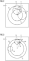
- FIG 2 or FIG 3 the respective center path 7a, 7b of the first milling cutter 3a or the second milling cutter 3b is also shown from above, i.e. parallel to the depth direction, for example Z.
- the resulting hole contours 6a, 6b are also shown.
- the same part program is used in both machining channels, i.e. the identical hole contours 6a, 6b and identical feed rates are programmed, in FIG 2 and FIG 3 as corresponding arrows 9a, 9b, the length of which corresponds to the amount of the programmed feed.
- the hole contours 6a, 6b are generated by the different center paths 7a, 7b, which result from the radius of the respective milling cutter 3a, 3b.
- the necessary feed for the machine axes in FIG 2 and FIG 3 represented by the arrows 10a, 10b with corresponding lengths, also depends on the radius of the respective milling cutter 3a, 3b.
- a maximum dynamic limit for the feed for the machine axes is represented by a corresponding arrow 8.
- FIG 2 and FIG 3 show the positions of the milling cutters 3a, 3b when the helix is completed by the first milling cutter 3a, which would then be at 12 o'clock again.
- the second milling cutter 3b would then be at 7 o'clock, for example, so that a corresponding path difference 11 would result. This path difference 11 can be reduced or prevented by the invention.
- the multi-spindle machine tool 1 can be used to achieve very high productivity in the smallest of spaces.
- the machine axes of the multi-spindle machine tool 1 can be operated close to their respective predetermined dynamic limits, whereby asynchrony can be reduced or prevented by the invention and thus the risk of collision can be reduced.
- Various embodiments of the invention create a new control function that allows the individual path movements, for example circles or helices, to be adjusted across different processing channels, i.e. in particular to be synchronized via the calculated or specified existing movement and orientation curve of the path planning in the CNC control in the respective processing channel. This is done in particular without any explicit specification in the part program itself.
- the forced synchronization can be implemented by reducing the path speed or reducing the speed of the machine axes involved in the movement in one of the processing channels, thus achieving the synchronicity of the two processing channels.
- other dynamic variables of the path such as path acceleration and/or path jerk, and/or dynamic variables of the machine axes, such as axis acceleration and/or axis jerk, can be adapted in order to improve the synchronicity of the two processing channels.
- the machining channel for the first milling cutter 3a would be deliberately slowed down because the center path 7a is shorter there.
- the synchronicity of the two machining channels can be achieved by internally generated, i.e. not explicitly programmed, stop intervals.
- a maximum static setting parameter for forced synchronization can be provided, which is determined by the difference in the tool dimensions.
- a further parameter can be a maximum dynamic distance, which results from measurements at the dynamic limits of the different tool corrections.
- the control function can easily synchronize a part program across two or more machining channels, particularly in the case of nominally identical tools with different levels of wear. This allows highly productive machine tools to be further improved and optimized. The introduction of such a control function increases machining speed and quality.
Landscapes
- Engineering & Computer Science (AREA)
- Human Computer Interaction (AREA)
- Manufacturing & Machinery (AREA)
- Physics & Mathematics (AREA)
- General Physics & Mathematics (AREA)
- Automation & Control Theory (AREA)
- Mechanical Engineering (AREA)
- Numerical Control (AREA)
Priority Applications (3)
| Application Number | Priority Date | Filing Date | Title |
|---|---|---|---|
| EP23169374.8A EP4455809A1 (fr) | 2023-04-24 | 2023-04-24 | Commande d'une machine-outil multibroche |
| US18/643,139 US20240353809A1 (en) | 2023-04-24 | 2024-04-23 | Control of a multi spindle machine tool |
| CN202410493345.9A CN118838246A (zh) | 2023-04-24 | 2024-04-23 | 多主轴机床的控制 |
Applications Claiming Priority (1)
| Application Number | Priority Date | Filing Date | Title |
|---|---|---|---|
| EP23169374.8A EP4455809A1 (fr) | 2023-04-24 | 2023-04-24 | Commande d'une machine-outil multibroche |
Publications (1)
| Publication Number | Publication Date |
|---|---|
| EP4455809A1 true EP4455809A1 (fr) | 2024-10-30 |
Family
ID=86185313
Family Applications (1)
| Application Number | Title | Priority Date | Filing Date |
|---|---|---|---|
| EP23169374.8A Pending EP4455809A1 (fr) | 2023-04-24 | 2023-04-24 | Commande d'une machine-outil multibroche |
Country Status (3)
| Country | Link |
|---|---|
| US (1) | US20240353809A1 (fr) |
| EP (1) | EP4455809A1 (fr) |
| CN (1) | CN118838246A (fr) |
Cited By (1)
| Publication number | Priority date | Publication date | Assignee | Title |
|---|---|---|---|---|
| EP4700508A1 (fr) * | 2024-08-21 | 2026-02-25 | Siemens Aktiengesellschaft | Synchronisation de canal dans des machines-outils multibroches |
Citations (3)
| Publication number | Priority date | Publication date | Assignee | Title |
|---|---|---|---|---|
| US5181178A (en) * | 1989-02-22 | 1993-01-19 | Fanuc Ltd. | Spindle control command method |
| EP0407589B1 (fr) * | 1988-10-11 | 1999-12-01 | Fanuc Ltd. | Systeme d'instructions de commande numerique |
| EP2325710A1 (fr) * | 2009-10-14 | 2011-05-25 | Tornos SA | Procédé et système de compenser les variations dimensionnelles dans une machine d'usinage |
-
2023
- 2023-04-24 EP EP23169374.8A patent/EP4455809A1/fr active Pending
-
2024
- 2024-04-23 US US18/643,139 patent/US20240353809A1/en active Pending
- 2024-04-23 CN CN202410493345.9A patent/CN118838246A/zh active Pending
Patent Citations (3)
| Publication number | Priority date | Publication date | Assignee | Title |
|---|---|---|---|---|
| EP0407589B1 (fr) * | 1988-10-11 | 1999-12-01 | Fanuc Ltd. | Systeme d'instructions de commande numerique |
| US5181178A (en) * | 1989-02-22 | 1993-01-19 | Fanuc Ltd. | Spindle control command method |
| EP2325710A1 (fr) * | 2009-10-14 | 2011-05-25 | Tornos SA | Procédé et système de compenser les variations dimensionnelles dans une machine d'usinage |
Cited By (2)
| Publication number | Priority date | Publication date | Assignee | Title |
|---|---|---|---|---|
| EP4700508A1 (fr) * | 2024-08-21 | 2026-02-25 | Siemens Aktiengesellschaft | Synchronisation de canal dans des machines-outils multibroches |
| WO2026041270A1 (fr) | 2024-08-21 | 2026-02-26 | Siemens Aktiengesellschaft | Synchronisation de canaux dans des machines-outils à broches multiples |
Also Published As
| Publication number | Publication date |
|---|---|
| CN118838246A (zh) | 2024-10-25 |
| US20240353809A1 (en) | 2024-10-24 |
Similar Documents
| Publication | Publication Date | Title |
|---|---|---|
| EP1981674B1 (fr) | Procede d'usinage de roues coniques dans un procede de division avec compensation complete des erreurs de division | |
| EP3335086B1 (fr) | Procede et dispositif de commande destines a la commande optimale d'une machine-outil | |
| DE4012432C1 (fr) | ||
| EP0751447B1 (fr) | Méthode de commande numérique | |
| EP3066533B1 (fr) | Procédé d'usinage d'une pièce brute au moyen d'un outil | |
| WO2010060596A1 (fr) | Procédé d'usinage des flancs de dentures sensiblement cylindriques, mais ayant un bombement modifié dans la largeur, lors d'un procédé de taillage diagonal par génération | |
| DE102015111964B4 (de) | Servomotoren-Steuersystem, das die Bearbeitungspräzision mehrerer Achsen verbessert | |
| DE112019007578T5 (de) | Numerische Steuerung, numerisches Steuerverfahren und Maschinenlernvorrichtung | |
| DE69110583T2 (de) | Numerische steuerung. | |
| EP3945381A1 (fr) | Fabrication de surfaces déterminables à l'aide des segments coniques au moyen d'une machine-outil | |
| WO2021052787A1 (fr) | Machine-outil pour usiner des dents, procédé d'usinage de flancs de dents d'une pièce à usiner et procédé de dressage d'un outil d'usinage de dents à l'aide d'une telle machine-outil | |
| EP0543034B1 (fr) | Procédé pour utilisation d'une machine-outil à commande numérique et machine-outil pour mettre en oeuvre le procédé | |
| EP4455809A1 (fr) | Commande d'une machine-outil multibroche | |
| EP4147102B1 (fr) | Fonctionnement d'une machine-outil au moins à deux axes | |
| EP3620251A1 (fr) | Procédé d'usinage de denture d'une pièce à usiner, machine à tailler les engrenages et logiciel correspondant | |
| EP4367561B1 (fr) | Procédé de compensation de la déviation d'un outil lors de l'usinage d'une pièce, et machine-outil associée | |
| EP4700508A1 (fr) | Synchronisation de canal dans des machines-outils multibroches | |
| EP4246256A1 (fr) | Usinage de pièces à vitesse optimisée de rotation de broche en fonction d'un point de coupe | |
| CH710569A2 (de) | Verfahren zum Bearbeiten eines Werkstücks mit einer mehrgängigen Schleifschnecke. | |
| EP2803435A2 (fr) | Procédé d'usinage de dentures sur des pièces à usiner | |
| EP4621507A1 (fr) | Fonctionnement d'une machine d'usinage d'une pièce | |
| WO2026046571A1 (fr) | Procédé de production de pièces uniformes | |
| DE102017129651A1 (de) | Verfahren zur Verzahnbearbeitung eines Werkstücks | |
| DE3908844A1 (de) | Numerische steuerung fuer werkzeugmaschinen oder roboter | |
| DE3116853A1 (de) | Verfahren und einrichtung zum numerisch gesteuerten bearbeiten eines werkstueckes gleichzeitig mit wenigstens zwei werkzeugen |
Legal Events
| Date | Code | Title | Description |
|---|---|---|---|
| PUAI | Public reference made under article 153(3) epc to a published international application that has entered the european phase |
Free format text: ORIGINAL CODE: 0009012 |
|
| STAA | Information on the status of an ep patent application or granted ep patent |
Free format text: STATUS: THE APPLICATION HAS BEEN PUBLISHED |
|
| AK | Designated contracting states |
Kind code of ref document: A1 Designated state(s): AL AT BE BG CH CY CZ DE DK EE ES FI FR GB GR HR HU IE IS IT LI LT LU LV MC ME MK MT NL NO PL PT RO RS SE SI SK SM TR |
|
| STAA | Information on the status of an ep patent application or granted ep patent |
Free format text: STATUS: REQUEST FOR EXAMINATION WAS MADE |
|
| 17P | Request for examination filed |
Effective date: 20250428 |