EP4456110A1 - Zusatzgerät für elektrische niederspannungsanlagen - Google Patents
Zusatzgerät für elektrische niederspannungsanlagen Download PDFInfo
- Publication number
- EP4456110A1 EP4456110A1 EP23170276.2A EP23170276A EP4456110A1 EP 4456110 A1 EP4456110 A1 EP 4456110A1 EP 23170276 A EP23170276 A EP 23170276A EP 4456110 A1 EP4456110 A1 EP 4456110A1
- Authority
- EP
- European Patent Office
- Prior art keywords
- protection device
- thermal
- accessory device
- accessory
- control module
- Prior art date
- Legal status (The legal status is an assumption and is not a legal conclusion. Google has not performed a legal analysis and makes no representation as to the accuracy of the status listed.)
- Withdrawn
Links
Images



Classifications
-
- H—ELECTRICITY
- H01—ELECTRIC ELEMENTS
- H01H—ELECTRIC SWITCHES; RELAYS; SELECTORS; EMERGENCY PROTECTIVE DEVICES
- H01H71/00—Details of the protective switches or relays covered by groups H01H73/00 - H01H83/00
- H01H71/04—Means for indicating condition of the switching device
-
- H—ELECTRICITY
- H01—ELECTRIC ELEMENTS
- H01H—ELECTRIC SWITCHES; RELAYS; SELECTORS; EMERGENCY PROTECTIVE DEVICES
- H01H71/00—Details of the protective switches or relays covered by groups H01H73/00 - H01H83/00
- H01H2071/006—Provisions for user interfaces for electrical protection devices
-
- H—ELECTRICITY
- H01—ELECTRIC ELEMENTS
- H01H—ELECTRIC SWITCHES; RELAYS; SELECTORS; EMERGENCY PROTECTIVE DEVICES
- H01H71/00—Details of the protective switches or relays covered by groups H01H73/00 - H01H83/00
- H01H71/02—Housings; Casings; Bases; Mountings
- H01H71/0264—Mountings or coverplates for complete assembled circuit breakers, e.g. snap mounting in panel
- H01H71/0271—Mounting several complete assembled circuit breakers together
- H01H2071/0278—Mounting several complete assembled circuit breakers together with at least one of juxtaposed casings dedicated to an auxiliary device, e.g. for undervoltage or shunt trip
Definitions
- the present invention relates to the field of low-voltage electrical installations. More particularly, the present invention relates to an accessory device configured to be operatively coupled to a low-voltage protection device to provide monitoring functionalities of the operating conditions of said protection device.
- Protection devices such as MCBs, RCCBs, RCBOs and the like, are widely used in low-voltage electrical installations, such as electric power distribution grids or switchboards.
- a protection device generally consists in a circuit breaker intended to be mounted on an electric line and typically configured to take two or three different operative states, namely a closed state, an open state and, possibly, a tripped state.
- the protection device operates in a closed state, at which it enables a current flow along the conductors of the electric line. Instead, when it switches in a tripped state or in an open state, the protection device interrupts the current flowing along the conductors of the electric line.
- a protection device In low-voltage installations, a protection device is often installed together with one or more accessory devices configured to provide signaling functionalities of the operating conditions of the protection device.
- Some accessory devices are designed to signal whether the protection device operatively coupled thereto has carried out an opening manoeuvre.
- Other accessory devices are configured to signal whether the protection device has carried out a tripping manoeuvre.
- the main aim of the present invention is to provide an accessory device for low-voltage electrical installations, which allows overcoming or mitigating the mentioned technical problems of the state of the art.
- an object of the present invention is to provide an accessory device, which is capable of providing improved monitoring services of the operating conditions of the protection device operatively coupled thereto.
- Another object of the present invention is to provide an accessory device relatively easy to manufacture at industrial level, at competitive costs with respect to currently available devices of similar kind.
- the accessory device is configured to be to be installed on a supporting structure together with and side by side a low-voltage protection device, for example a MCB, RCCB, RCBO, and the like.
- a low-voltage protection device for example a MCB, RCCB, RCBO, and the like.
- the accessory device is further configured to communicate with an outer electronic device, which may be, for example, a local control device.
- the accessory device comprises an insulating enclosure having a side portion facing said protection device, when said accessory device is installed on said supporting structure together with said protection device.
- the accessory device comprises a plurality of thermal sensors arranged at said side portion of the insulating enclosure and configured to detect temperatures at a plurality of thermal monitoring spots of said protection device, when said accessory device is installed on said supporting structure together with said protection device.
- Said thermal sensors are arranged at selected positions, which are distributed along said side portion.
- the position of each thermal sensor conveniently corresponds to a desired thermal monitoring spot of the protection device, which is conveniently located in proximity of a given internal component of the protection device.
- said thermal sensors have a thermal contact surface in thermal contact with said side portion of the insulating enclosure. Said side portion is, in turn, in thermal contact with said protection device, when said accessory device is installed on said supporting structure together with said protection device.
- said thermal sensors have a thermal contact surface in thermal contact with said protection device, when said accessory device is installed on said supporting structure together with said protection device.
- the above-mentioned thermal sensors include two or more thermal sensors among:
- the accessory device comprises a control module electrically connected to said thermal sensors. These latter are configured to transmit thermal detection signals to said control module, which are indicative of temperatures detected by said thermal sensors during operation of said protection device. Said control module is configured to receive and process said thermal detection signals and provide first detection information indicative of a thermal behaviour of said protection device based on said thermal detection signals.
- the above-mentioned thermal sensors are of the NTC type.
- the accessory device is configured to provide signaling services of an open state of said protection device.
- the accessory device comprises a first lever protruding from said insulating enclosure and configured to be solidly coupled to a first mechanical component of said protection device.
- Said first mechanical component is configured to move during an opening manoeuvre of said protection device.
- said first mechanical component is a handle of said protection device, which may be manually operated by a user or an actuator to carry out an opening manoeuvre of said protection device.
- the above-mentioned first lever is configured to move from a first position to a second position, upon actuation by the first mechanical component of said protection device, when said protection device carries out an opening manoeuvre.
- the accessory device further comprises a motion transmission mechanism mechanically coupled to said first lever and operatively coupled to a first switch circuit, which preferably includes a first microswitch mechanically coupled to said motion transmission mechanism in such a way to be actuatable by said motion transmission mechanism.
- the motion transmission mechanism is configured to activate the switch circuit in response to a movement of said first lever from said first position to said second position (preferably by actuating the first microswitch).
- Said first switch circuit is electrically connected to said control module and it is configured to provide a first state detection signal, which is indicative of an open state taken by said protection device during operation of said protection device, to said control module in response to the activation by said motion transmission mechanism (preferably in response to the actuation of said first microswitch by said motion transmission mechanism).
- the accessory device is configured to provide signaling services of a tripping manoeuvre of said protection device.
- the accessory device comprises a second lever protruding from said insulating enclosure and configured to be solidly coupled to a second mechanical component of said protection device.
- Said second mechanical component is configured to move during a tripping manoeuvre of said protection device.
- said second mechanical component is a trip lever of said protection device, which trips during a tripping manoeuvre of said protection device.
- the above-mentioned second lever is configured to move from a third position to a fourth position, upon actuation by the second mechanical component of said protection device, when said protection device carries out a tripping manoeuvre.
- Said motion transmission mechanism is mechanically coupled to said second lever.
- the accessory device comprises a second switch circuit, to which said motion transmission lever is operatively coupled.
- the second switch circuit preferably includes a second microswitch mechanically coupled to said motion transmission mechanism in such a way to be actuatable by said motion transmission mechanism.
- Said motion transmission mechanism is configured to activate said second switch circuit in response to a movement of said second lever from said third position to said fourth position (preferably by actuating the second microswitch).
- Said second switch circuit is electrically connected to said control module and it is configured to provide a second state detection signal to said control module in response to the activation of said second switch circuit by said motion transmission mechanism (preferably in response to the actuation of said second microswitch by said motion transmission mechanism).
- Said second state detection signal is indicative of a tripping manoeuvre carried out by said protection device, during operation of said protection device.
- control module of said accessory device is configured to receive and process the above-mentioned first state detection signal, and possibly the above-mentioned second state detection signal.
- Said control module is configured to provide second detection information indicative of an operating state taken by said protection device based on said first state detection signal, and possibly on said second state detection signal.
- the accessory device comprises a communication module electrically connected to said control module.
- Said communication module is configured to allow said control module to communicate with an electronic device by using a data packet communication mode.
- the accessory device comprises a power supply module electrically connected to one or more electronic components of said accessory device.
- said power supply module is configured to receive a power supply voltage to feed said electronic components from said electronic device.
- said communication module and said power supply module are operatively coupled to a single cable interface configured to be connected to a bus cable, which is connectable to said electronic device.
- the accessory device comprises an interface module electrically connected to said control module.
- Said interface module includes signaling means driven by said control module and user interface means configured to allow a user to send data signals or command signals to said control module.
- the present invention relates to an electrical installation according to claim 13 and related independent claims.
- the present invention relates to a diagnostic method, according to claim 15. Further characteristics and advantages of the invention will become apparent from the detailed description of exemplary embodiments of the protection device, which is illustrated only by way of non-limitative examples in the accompanying drawings, wherein:
- the present invention relates to an accessory device 1 for low-voltage electrical installations.
- LV low voltage
- the accessory device 1 is intended to be operatively associated to a low-voltage protection device 10, for example a MCB, RCCB, RCBO, and the like.
- the protection device 10 is electrically connected to an electric line 101 and it is configured to allow or interrupt a current flow between different sections of said electric line.
- the protection device comprises an insulating enclosure 11 and a number of internal components 15, 16 accommodated in the internal volume defined by said insulating enclosure.
- the protection device 10 may be arranged according to different configurations.
- the protection device 10 can take three different operative states, namely a closed state, a tripped state and an open state.
- the protection device 10 can take two different operative states only, namely a closed state and an open state.
- the protection device 10 Normally, the protection device 10 operates in a closed state, at which it allows a current to flow along the electric line 101 between the upstream and downstream sections of this latter. When it switches in a tripped state or in an open state, the protection device 10 interrupts the current flow along the electric line 101, thereby electrically disconnecting the upstream and downstream portions of this latter.
- the protection device 10 is configured to switch automatically from the closed state to a tripped state or to an open state (tripping manoeuvre) in case of fault conditions (e.g., for example, ground fault conditions, arc fault conditions, overvoltage conditions, short-circuit conditions, and the like) in the electric line or, in some cases, in the protection device itself.
- the protection device 10 is configured to switch from a closed state to an open state (opening manoeuvre) upon actuation by a user or by another driving device (e.g., an electro-mechanical actuator) operatively coupled thereto.
- the accessory device 1 is configured to communicate with an electronic device 90, which may be, for example, a local control device adapted to collect information from a number of installed field devices and manage the operation of protection devices and possibly, other electronic devices included in the electrical installation.
- an electronic device 90 may be, for example, a local control device adapted to collect information from a number of installed field devices and manage the operation of protection devices and possibly, other electronic devices included in the electrical installation.
- the local control device 90 is, in turn, configured to communicate with remote computerized devices or platforms, for example via the Internet or a dedicated LAN.
- the protection device 10 and the electronic device 90 may be industrially arranged according to solutions of known type. Therefore, in the following, they will be described only in relation to the aspects of interest of the invention, for the sake of brevity.
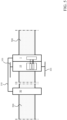
- the accessory device 1 is installed on a supporting structure 500 together with the protection device 10 and, possibly, the electronic device 90 (as shown in figure 5 ).
- the supporting structure 500 may be, for example, a DIN rail or a similar support arrangement.
- the accessory device 1 comprises an insulating enclosure 2 (preferably made of an electrically insulating material) adapted to be fixed to the supporting structure 500.
- the insulating enclosure 2 of the switch pole is shaped as a contoured box with opposite front and rear walls 21, 22, opposite side walls 23, 24 and top and bottom walls 25, 26.
- the insulating enclosure 2 is preferably formed by a pair of half shells coupled one to another.
- a first half shell comprises a portion of the front wall 21, a first side wall 23, a portion of the rear wall 22, a portion of the top wall 25 and a portion of the bottom wall 26, while a second half shell comprises a further portion of the front wall 21, a second side wall 24, a further portion of the rear wall 22, a further portion of the top wall 25 and a further portion of the bottom wall 26.
- the insulating enclosure 2 thus includes a side portion 230 facing the protection device 10, namely a corresponding side portion of the insulating enclosure of this latter.
- the side portion 230 of the insulating enclosure 2 is put in thermal contact with the protection device 20, more particularly with the insulating enclosure 11 of this latter, when installed as described above.
- thermal contact refers to arrangements, in which two components or bodies are attached or put in proximity one to another in such a way that there can be a transmission of heat from a body to another.
- the above-mentioned side portion 230 is part of a first side wall 23 of the insulating enclosure. According to other embodiments of the invention, however, the side portion of the insulating enclosure 2, which is intended to face the protection device 10, may be located at the opposite second side wall 24 of the insulating enclosure.
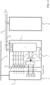
- the accessory device 1 comprises a control module 3 accommodated in the internal volume defined by the insulating enclosure 2.
- the control module 3 may include data processing resources, preferably of digital type, e.g., one or more microcontrollers capable of executing stored software instructions.
- control module 3 is configured to carry out control tasks to control the operation of the accessory device, data processing tasks for processing detection signals coming from suitable sensors or switches of the accessory device and, possibly, communication tasks with an outer electronic device.
- the accessory device 1 is preferably configured to communicate at local level with an outer electronic device 90 operatively associated thereto.
- the accessory device 1 comprises a communication module 4 operatively connected (electrically connected) to the control module 3.
- the communication module 4 is configured to allow the control module 3 to communicate with the electronic device 90 according to a data packet communication mode.
- the communication module 4 is configured to allow the control module 3 to communicate with the electronic device 90 in a wired mode.
- the communication module 4 may include, for example, a communication port configured be electrically connected to a RS485 cable and communicate through a Modbus TM communication protocol.
- the communication module 4 may be configured to allow the control module 3 to communicate with the electronic device 90 in a wireless mode.
- the communication module 4 may include, for example, a communication port configured to communicate at local level through a wireless communication protocol, such as Wi-Fi TM , Bluetooth TM , Zigbee TM , and the like.
- the accessory device 1 comprises a power supply module 9 electrically connected to the internal electronic components (e.g., the control module 3) of the accessory device and configured to feed said electronic components.
- a power supply module 9 electrically connected to the internal electronic components (e.g., the control module 3) of the accessory device and configured to feed said electronic components.
- the power supply module 9 includes suitable electronic circuits configured to draw electric power from an outer power source and provide suitable power supply voltages to the electronic components of the accessory device.
- such a power supply source is advantageously the electronic device 90 communicating with the accessory device.
- the accessory device 1 may be any suitable device or circuit adapted to provide an auxiliary power supply.
- the accessory device 1 is electrically connected to the electronic device 90 by means of a bus cable 110 (e.g., a flat cable) including a communication line 102 and a power supply line 103.
- the above-mentioned communication module 4 and power supply module 9 are operatively coupled to a single cable interface 49 configured to be mechanically and electrically connected to the bus cable 110, which is in turn configured to be mechanically and electrically connected to the electronic device 90.
- the cable interface 49 includes a connector 490 having first pins and second pins (not shown) configured to be electrically connected to the communication line 102 and the power supply line 103 of the bus cable 110, respectively.
- the accessory device 1 can thus communicate in a wired manner with the electronic device 90 and, at the same time, be fed by this latter.
- the accessory device 1 comprises an interface module 6 electrically connected to the control module 3.
- the interface module 6 includes suitable signaling means driven by the control module 3.
- said signaling means may include one or more LEDs arranged on the front wall 21 of the insulating enclosure 3 and configured to emit light signals indicative of the operating conditions of the accessory device 1 or the protection device 10.
- the interface module 6 includes user interface means configured to allow a user to send data signals or command signals to the control module.
- said user interface means may include one or more buttons arranged on the front wall 21 of the insulating enclosure 3 and manually operable by the user to send data signals (e.g., configuration signals) or command signals (e.g., reset commands or configuration signals) to the control module 3.
- the communication module 4, the power supply module 9 and the interface module 6 may be industrially arranged according to solutions of known type. Therefore, in the following, they will be described only in relation to the aspects of interest of the invention, for the sake of brevity.
- the accessory device 1 is configured to monitor the thermal behaviour of the protection device 10, while this latter is operating.
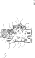
- the accessory device 1 comprises a plurality of thermal sensors T A , T B , Tc, T D , T E arranged at the side portion 230 of the insulating enclosure 2.
- the thermal sensors T A , T B , Tc, T D , T E detect temperatures at a plurality of thermal monitoring spots Z A , Z B , Z C , Z D , Z E of the protection device.
- a "thermal monitoring spot" of the protection device is a region of the protection device selected in such a way to allow monitoring the temperature variations of a corresponding internal component of the protection device, while this latter is operating.
- the thermal monitoring spots Z A , Z B , Z C , Z D , Z E of the protection device are regions of the insulating enclosure of the protection device, which are located in proximity of critical internal components of the protection device. Variations of temperatures at the thermal monitoring spots Z A , Z B , Z C , Z D , Z E may thus be indicative of possible anomalous conditions of such internal components in the protection device 10.
- the thermal sensors T A , T B , Tc, T D , T E are arranged at selected positions P A , P B , P C , P D , P E that are distributed along the side portion 230 of the insulating enclosure 2.
- the position of each thermal sensors T A , T B , T C , T D , T E corresponds to a thermal monitoring spot Z A , Z B , Z C , Z D , Z E of the protection device 10.
- the detection of possible "hot spots" by the thermal sensors T A , T B , T C , T D , T E may therefore indicate that anomalous conditions of such internal components in the protection device 10 are present.
- the above-mentioned thermal sensors comprise a first thermal sensor T A and a second thermal sensor T B arranged respectively at a first position P A , which corresponds to a first thermal monitoring spot Z A of the protection device, and at a second position P B , which corresponds to a second thermal monitoring spot Z B of the protection device.
- the first thermal monitoring spot Z A and the second thermal monitoring spot Z B are respectively located in proximity of a first electric terminal and of a second electric terminal of the protection device 10.
- the thermal sensors T A , T B allow monitoring the thermal behaviour of the electric terminals of the protection device 10, at which this latter is electrically connected to the electric line 101.
- An anomalous temperature increase detected by the thermal sensor T A or T B may be indicative of loose electrical connections between the electric terminals of the protection device 10 and the corresponding conductor of the electric line 101.
- the above-mentioned thermal sensors comprise a third thermal sensor Tc arranged respectively at a third position Pc, which corresponds to a third thermal monitoring spot Zc of the protection device.
- the third thermal monitoring spot Zc is located in proximity of the contact region of the protection device 10.
- the thermal sensor Tc allows monitoring the thermal behaviour of the separable arcing contacts of the protection device 10.
- An anomalous temperature increase detected by the thermal sensor Tc may be indicative of the presence of welding spots between the electric contacts or of an excessive erosion of these latter.
- the above-mentioned thermal sensors comprise a fourth thermal sensor T D arranged respectively at a fourth position P D , which corresponds to a fourth thermal monitoring spot Z D of the protection device.
- the fourth thermal monitoring spot Z D is located in proximity of tripping means of the protection device 10.
- the thermal sensor T D thus allows monitoring the thermal behaviour of the tripping means of the protection device 10, which are configured to cause a tripping manoeuvre of the protection device in case of overload or short-circuit events in the electric line 101.
- An anomalous temperature increase detected by the thermal sensor T D may be indicative of an incoming fault at bi-metal actuator or trip coil actuator of the protection device.
- the above-mentioned thermal sensors comprise a fifth thermal sensor T E arranged respectively at a fifth position P E , which corresponds to a fifth thermal monitoring spot Z E of the protection device.
- the fifth thermal monitoring spot Z E is located in proximity of a colder part of said protection device compared to other parts of said protection device.
- the fifth thermal monitoring spot Z E is located in proximity of a part of the protection device, which does not warm up appreciably while this latter is operating.
- the fifth thermal monitoring spot Z E is generally a "cold spot" of the protection device, the temperature of which is very close to the temperature of the environment, where the protection device is installed.
- the arrangement of the thermal sensor T E is particularly useful as it allows fixing a baseline temperature for the temperatures detected by other thermal sensors distributed along the side portion 230.
- the accessory device 1 comprises all the thermal sensors T A , T B , T C , T D , T E described above. According to other embodiments, however, the accessory device may include just some of the above-described thermal sensors. As it is evident to the skilled person, the accessory device 1 may also include additional thermal sensors with respect to those described above. Preferably, also these additional thermal sensors are distributed along the side portion 230 of the insulating enclosure 2 and are advantageously configured to detect temperatures at further thermal monitoring spots of the protection device.
- the thermal sensors T A , T B , Tc, T D , T E of the accessory device are configured to transmit thermal detection signals D A , D B , D C , D D , D E to the control module 3. Said thermal detection signals are indicative of the temperatures detected by said thermal sensors during the operation of the protection device 10.
- the control module 3 is configured to receive and process the thermal detection signals D A , D B , D C , D D , D E and, based on these latter, provide first detection information I T indicative of a thermal behaviour of the protection device 10.
- the first detection information I T may advantageously include suitable detection data, such as temperature values detected by the thermal sensors T A , T B , Tc, T D , T E or other thermal values (e.g., temperature variation values, relative temperature values, and the like), which can be obtained by suitably processing the thermal detection signals D A , D B , Dc, D D , D E .
- suitable detection data such as temperature values detected by the thermal sensors T A , T B , Tc, T D , T E or other thermal values (e.g., temperature variation values, relative temperature values, and the like), which can be obtained by suitably processing the thermal detection signals D A , D B , Dc, D D , D E .
- control module 3 sends the first detection information I T to the electronic device 90, which may process it for diagnostic purposes, as described in the following.
- control module 3 may be configured to carry out some diagnostic functionalities at local level.
- the first detection information I T conveniently include also diagnostic data and, possibly, alarm messages to be further processed by the electronic device 90.
- the thermal sensors T A , T B , Tc, T D , T E may be arranged together with most of the other internal electronic components of the accessory device (e.g., the electronic modules 3, 4, 6, 9 described above) on a suitable circuit support member 29 (for example a printed circuit board) accommodated in the internal volume defined by the insulating enclosure.
- a suitable circuit support member 29 for example a printed circuit board
- the thermal sensors T A , T B , Tc, T D , T E have a thermal contact surface in thermal contact (attached or in proximity) with the side portion 230 of the insulating enclosure 2.
- the side portion 230 is, in turn, in thermal contact (attached or in proximity) with the protection device, preferably with an insulating enclosure of this latter, when the accessory device is installed on the supporting structure 500 together with the protection device.
- the thermal sensors T A , T B , Tc, T D , T E may be arranged on the circuit member 29 in such a way to be located just behind the side portion 230 of the insulating enclosure.
- the thermal sensors T A , T B , Tc, T D , T E may have their thermal contact surfaces thermally bonded to the internal surface of the side portion of the insulating enclosure.
- a thermally conductive bonding material such as thermally conductive silicone, may be used.
- the thermal sensors T A , T B , Tc, T D , T E have their thermal contact surfaces in thermal contact (attached or in proximity) with the protection device 10, preferably with an insulating enclosure of this latter when the accessory device is installed on the supporting structure 500 together with the protection device.
- the insulating enclosure 2 conveniently comprises a plurality of ports at the side portion 230, each located at a corresponding position P A , P B , P C , P D , P E selected for a thermal sensor T A , T B , Tc, T D , T E .
- each thermal sensor T A , T B , Tc, T D , T E is arranged at a corresponding port of the insulating enclosure in such a way to have a thermal contact surface substantially flush or slightly or slightly recessed relative to an outer surface of the side portion 230.
- the thermal sensors T A , T B , Tc, T D , T E have their thermal contact surfaces thermally bonded to the insulating enclosure of the protection device 10.
- a thermally conductive bonding material may be suitably used.
- the thermal sensor T A , T B , Tc, T D , T E are of the NTC type.
- other kinds of thermal sensors may be conveniently used, according to the needs.
- the accessory device 1 is configured to monitor whether the protection device 10 takes an open state in operation.
- the accessory device 1 comprises a first lever 7 protruding from the insulating enclosure 2 of the accessory device, a motion transmission mechanism 5 mechanically coupled to said first lever and operatively coupled to a first switch circuit 51 electrically connected to the control module 3.
- the first switch circuit 51 includes a first microswitch W A mechanically coupled to said motion transmission mechanism in such a way that it can be actuated by this latter.
- the first lever 7 is solidly coupled to a first mechanical component 15 of the protection device 10, which moves from a corresponding closing position to an opening position, when the protection device 10 carries out an opening manoeuvre or a tripping manoeuvre.
- the first mechanical component 15 is the handle of the protection device 10 or another mechanical component solidly coupled with said handle in such a way to move together with this latter.
- the first lever 7 moves from a first position to a second position, upon actuation by the first mechanical component 15 of the protection device.
- the motion transmission mechanism 5 activates the switch circuit 51.
- This latter provides a first state detection signal S A to the control module 3 in response to the activation by the motion transmission mechanism.
- the first state detection signal S A is indicative of an open state taken by the protection device.
- the motion transmission mechanism 5 actuates the first microswitch W A of the first switch circuit 51 in response to the movement of the first lever 7 and the switch circuit 51 provides the first state detection signal S A in response to the actuation of the first microswitch.
- the switch circuit 51 may include a different device (for example a magnetic device, a hall sensor, a photocell, a photoelectric sensor, and the like) activated in response to a motion of the motion transmission mechanism.
- the accessory device 1 may be also configured to monitor whether the protection device 10 carries out a tripping manoeuvre in operation.
- the accessory device 1 comprises a second lever 8 protruding from the insulating enclosure 2 of the accessory device and a second switch circuit 52, to which the motion transmission mechanism 5 is operatively coupled.
- the second switch circuit 52 includes a second microswitch W B mechanically coupled to the motion transmission mechanism 5.
- the second switch circuit 52 is electrically connected to the control module 3.
- the second lever 8 When the accessory device is installed on the supporting structure 500 together with the protection device 10, the second lever 8 is solidly coupled to a second mechanical component 16 of the protection device 10, which moves from a corresponding closing position to a tripping position, when the protection device 10 carries out a tripping manoeuvre.
- the second mechanical component 16 is a trip lever of the protection device 10 or another mechanical component solidly coupled with said trip lever in such a way to move together with this latter.
- the second lever 8 moves from a third position to a fourth position, upon actuation by the second mechanical component 16 of the protection device.
- the motion transmission mechanism 5 activates the switch circuit 52.
- This latter provides a second state detection signal S B to the control module 3 in response to the activation by the motion transmission mechanism.
- the second state detection signal S B is indicative of a tripping manoeuvre carried out by the protection device.
- the motion transmission mechanism 5 actuates the second microswitch W B of the second switch circuit 52 in response to the movement of the second lever 8 and the switch circuit 52 provides the second state detection signal S B in response to the actuation of the second microswitch.
- the switch circuit 52 may include a different device (for example a magnetic device, a hall sensor, a photocell, a photoelectric sensor, and the like) activated in response to a motion of the motion transmission mechanism.
- a different device for example a magnetic device, a hall sensor, a photocell, a photoelectric sensor, and the like
- the control module 3 is configured to receive and process the first state detection signal S A provided by the first switch circuit 51, and possibly the second state detection signal S B provided by the second switch circuit 52.
- the control module 3 Based on the first state detection signal S A , and possibly on the second state detection signal S B , the control module 3 provides second detection information Is indicative of an operating state taken the protection device 10.
- the second detection information I T may advantageously include suitable logic values indicative of the operating state taken by the protection device 10, which can be obtained by suitably processing the state detection signals S A , S B .
- control module 3 sends the second detection information Is to the electronic device 90, which is conveniently configured to process said information for signaling purposes.
- the first and second levers 7, 8 may be formed by suitable pins protruding from the insulating enclosure 2, the first and second switch circuit 51, 52 may be arranged on the circuit support member 29 while the motion transmission mechanism 5 may be accommodated in a suitable portion of the internal volume defined by the insulating enclosure 2.
- levers 7, 8, the motion transmission mechanism 5 and the switch circuits 51, 52 may be industrially arranged according to solutions of known type. Therefore, in the following, they will be described only in relation to the aspects of interest of the invention, for the sake of brevity.
- FIG. 5 shows a typical low-voltage electrical installation including the accessory device, according to the invention.
- Such an electrical installation comprises:
- the electronic device 90 is electrically connected to the accessory device 1 through a flat cable 110, which includes a communication line 102 and a power supply line 103.
- the electronic device 90 and the accessory device can thus communicate in a wired manner and the accessory device 1 is electrically fed by the electronic device 90.
- the electronic device 90 is advantageously configured to receive and process first detection information I T indicative of a thermal behaviour of the protection device 10, which is provided by the accessory device 1.
- the electronic device 90 is also configured to receive and process the second detection information Is indicative of an operating state taken by the protection device 10, which is provided by the accessory device 1.
- the electronic device 90 may be installed side by side the protection device (on an opposite side relative to the accessory device) or side by side the accessory device (on an opposite side relative to the protection device).
- the electronic device 90 may be installed on a different supporting structure compared to the support structure 500, on which the protection device 10 and the accessory device 1 are installed.
- the electronic device 90 may be installed at a certain distance from the protection device 10 and the accessory device 1.
- the information provided by the thermal sensors T A , T B , Tc, T D , T E of the accessory device may be conveniently processed for carrying out diagnostic procedures directed to check the thermal behaviour of the protection device 10.
- the present invention is related to a diagnostic method 1000 for checking a thermal behaviour of a protection device 10, to which the accessory device 10 is operatively coupled as described above.
- the diagnostic method 1000 is carried out by the electronic device 90 based on detection data D T included in the first diagnostic information I T provided by the accessory device.
- the diagnostic method 1000 might be carried by the control module 3 of the accessory device itself based on detection data D T directly calculated by said control module.
- the first diagnostic information I T provided to the electronic device 90 will include diagnostic data and, possibly, alarm messages to be further processed by the electronic device 90.
- the diagnostic method 1000 comprises a step 1001 of acquiring detection data D T indicative of the thermal behaviour of the protection device 10.
- the detection data D T are calculated by the accessory device 1 by suitably processing the thermal detection signals D A , D B , Dc, D D , D E provided by the thermal sensors T A , T B , Tc, T D , T E .
- They may advantageously include temperature values detected by the above-mentioned thermal sensors or other thermal values calculated by processing the above-mentioned temperature values.
- the detection data D T will be part of the first detection information I T sent by the accessory device 1 to the electronic device 90.
- the detection data D T will be immediately available to the control module 3 upon processing the thermal detection signals provided by the thermal sensors.
- the diagnostic method 1000 then comprises a step 1002 of calculating first diagnostic data M T indicative of a thermal condition of the protection device 10 based on the acquired detection data D T .
- the first diagnostic data M T conveniently includes a thermal map of the protection device 10.
- the diagnostic method 1000 comprises a step 1003 of comparing the calculated first diagnostic data M T with predefined second diagnostic data Mo indicative of a reference thermal condition of the protection device.
- the second diagnostic data Mo are conveniently stored in a memory and they may be selected depending on additional detection information related to operating conditions of said protection device 10.
- additional detection information may include data related to operating currents and voltages of the protection device as detected by suitable sensors of the electrical installation, data indicative of the operating age of the protection device, and the like.
- the above-mentioned additional detection information may be provided to the electronic device by the accessory device itself or by suitable sensors or additional electronic devices communicating with the electronic device 90.
- the above-mentioned additional detection information may be provided to the control module 3 of the accessory device by electronic device 90.
- the diagnostic method 1000 comprises a step 1004 of providing an alarm message A L , if the first diagnostic data M T do not match with the second diagnostic data Mo.
- the comparison between the first and second diagnostic data M T , Mo has allowed to identify anomalies in the thermal behaviour of the protection device, which may be indicative of possible incoming faults or possible installation or manufacturing errors in the protection device.
- the above-mentioned alarm messages may be sent to remote computerized devices or platforms directly by the electronic device 90.
- the above-mentioned alarm messages may be sent to the electronic device 90 by the accessory device.
- the electronic device 90 may send these alarm messages to remote computerized devices or platforms.
- the diagnostic method 1000 is executed cyclically by the electronic device 90 or by the control module 3 of the accessory device.
- the first diagnostic data M T (thermal map) of the protection device 10 will be updated based on newly acquired detection data D T made available by the accessory device by processing the thermal detection signals provided by the thermal sensors.
- the accessory device 1 provides improved monitoring services of the operating conditions of the protection device operatively coupled thereto.
- the accessory device in addition to the most traditional signaling services related to the operating state of the protection device, the accessory device is capable of providing relevant detection data related to the thermal behaviour of the protection device, which may be conveniently exploited for carrying out an effective diagnostics directed to identify possible incoming faults or possible installation or manufacturing errors in the protection device.
- the accessory device 1 has a compact structure and it requires a relatively small place for its installation on the field. Wiring operations between the accessory device 1 and the electronic device 90 are relatively simple as these latter devices are at most connected by a suitable bus cable.
- the accessory device 1 has proven to be easy to industrially manufacture, at competitive costs with respect to currently available protection devices.
Landscapes
- Breakers (AREA)
- Cooling Or The Like Of Electrical Apparatus (AREA)
Priority Applications (2)
| Application Number | Priority Date | Filing Date | Title |
|---|---|---|---|
| EP23170276.2A EP4456110A1 (de) | 2023-04-27 | 2023-04-27 | Zusatzgerät für elektrische niederspannungsanlagen |
| DE202024102062.6U DE202024102062U1 (de) | 2023-04-27 | 2024-04-24 | Zusatzvorrichtung für Niederspannungs-Elektroinstallationen |
Applications Claiming Priority (1)
| Application Number | Priority Date | Filing Date | Title |
|---|---|---|---|
| EP23170276.2A EP4456110A1 (de) | 2023-04-27 | 2023-04-27 | Zusatzgerät für elektrische niederspannungsanlagen |
Publications (1)
| Publication Number | Publication Date |
|---|---|
| EP4456110A1 true EP4456110A1 (de) | 2024-10-30 |
Family
ID=86272172
Family Applications (1)
| Application Number | Title | Priority Date | Filing Date |
|---|---|---|---|
| EP23170276.2A Withdrawn EP4456110A1 (de) | 2023-04-27 | 2023-04-27 | Zusatzgerät für elektrische niederspannungsanlagen |
Country Status (2)
| Country | Link |
|---|---|
| EP (1) | EP4456110A1 (de) |
| DE (1) | DE202024102062U1 (de) |
Citations (2)
| Publication number | Priority date | Publication date | Assignee | Title |
|---|---|---|---|---|
| US20170047184A1 (en) * | 2015-08-13 | 2017-02-16 | Eaton Corporation | Electromechanical device for prognostic and diagnostic health assessment of a power circuit breaker's power transmission and distribution system in real time |
| EP3863037A1 (de) * | 2020-02-10 | 2021-08-11 | Siemens Aktiengesellschaft | Neues zubehörteil für schutzschalterstatusvoralarm und -überwachung |
-
2023
- 2023-04-27 EP EP23170276.2A patent/EP4456110A1/de not_active Withdrawn
-
2024
- 2024-04-24 DE DE202024102062.6U patent/DE202024102062U1/de active Active
Patent Citations (2)
| Publication number | Priority date | Publication date | Assignee | Title |
|---|---|---|---|---|
| US20170047184A1 (en) * | 2015-08-13 | 2017-02-16 | Eaton Corporation | Electromechanical device for prognostic and diagnostic health assessment of a power circuit breaker's power transmission and distribution system in real time |
| EP3863037A1 (de) * | 2020-02-10 | 2021-08-11 | Siemens Aktiengesellschaft | Neues zubehörteil für schutzschalterstatusvoralarm und -überwachung |
Also Published As
| Publication number | Publication date |
|---|---|
| DE202024102062U1 (de) | 2024-09-05 |
Similar Documents
| Publication | Publication Date | Title |
|---|---|---|
| US6788508B2 (en) | Compact low AMP electronic circuit breaker or residential load center | |
| CN101345173B (zh) | 成组保险模块及具有该成组保险模块的开关设备装置 | |
| JP4237061B2 (ja) | スイッチ装置の制御及び保護モジュール | |
| EP3078090B1 (de) | Verfahren und vorrichtung zur erfassung des zustandes eines schutzschalters | |
| JP2009022158A6 (ja) | スイッチギア装置のためのグループ保護モジュール及びかかるグループ保護モジュールを有するスイッチギア装置 | |
| CN104170049A (zh) | 具有嵌入式电弧故障保护的电气开关设备及采用此设备的系统 | |
| JP4611425B2 (ja) | 電磁開閉機器を備えた結線装置 | |
| CN211629005U (zh) | 一种集成在断路器中的电路故障检测模块 | |
| US8842407B2 (en) | Medium voltage circuit breaker | |
| CN116458025A (zh) | 电子开关式保护设备 | |
| EP1814133B1 (de) | Schaltvorrichtung | |
| EP3863037B1 (de) | Neues zubehörteil für schutzschalterstatusvoralarm und -überwachung | |
| CN109728644B (zh) | 开关装置和控制方法 | |
| CN110506376B (zh) | 电切换装置 | |
| EP4456110A1 (de) | Zusatzgerät für elektrische niederspannungsanlagen | |
| US6612873B2 (en) | Wiring adapter for connecting a remotely operable switching device to a control bus | |
| JP7122567B2 (ja) | 開閉器及び分電盤 | |
| RU2541517C2 (ru) | Автоматический выключатель | |
| JP2003100193A (ja) | 回路遮断装置 | |
| CN111276374B (zh) | 低压保护开关装置 | |
| CN113258668B (zh) | 远程驱动器、装置及测试方法 | |
| CN113258667A (zh) | 远程驱动器、具有远程驱动的装置以及方法 | |
| CN111542905B (zh) | 模块化电力切换设备 | |
| CN219418939U (zh) | 一种多结构一体化智能微型断路器 | |
| EP4270438B1 (de) | Zustandsanzeigevorrichtung für schwachstromanwendungen mit breiterem betriebsbereich |
Legal Events
| Date | Code | Title | Description |
|---|---|---|---|
| PUAI | Public reference made under article 153(3) epc to a published international application that has entered the european phase |
Free format text: ORIGINAL CODE: 0009012 |
|
| STAA | Information on the status of an ep patent application or granted ep patent |
Free format text: STATUS: THE APPLICATION HAS BEEN PUBLISHED |
|
| AK | Designated contracting states |
Kind code of ref document: A1 Designated state(s): AL AT BE BG CH CY CZ DE DK EE ES FI FR GB GR HR HU IE IS IT LI LT LU LV MC ME MK MT NL NO PL PT RO RS SE SI SK SM TR |
|
| STAA | Information on the status of an ep patent application or granted ep patent |
Free format text: STATUS: THE APPLICATION IS DEEMED TO BE WITHDRAWN |
|
| 18D | Application deemed to be withdrawn |
Effective date: 20250501 |