EP4456209A1 - Plaque bipolaire gaufrée - Google Patents
Plaque bipolaire gaufrée Download PDFInfo
- Publication number
- EP4456209A1 EP4456209A1 EP24170537.5A EP24170537A EP4456209A1 EP 4456209 A1 EP4456209 A1 EP 4456209A1 EP 24170537 A EP24170537 A EP 24170537A EP 4456209 A1 EP4456209 A1 EP 4456209A1
- Authority
- EP
- European Patent Office
- Prior art keywords
- main surface
- bipolar plate
- elevations
- elevation
- fluid
- Prior art date
- Legal status (The legal status is an assumption and is not a legal conclusion. Google has not performed a legal analysis and makes no representation as to the accuracy of the status listed.)
- Pending
Links
Images


Classifications
-
- H—ELECTRICITY
- H01—ELECTRIC ELEMENTS
- H01M—PROCESSES OR MEANS, e.g. BATTERIES, FOR THE DIRECT CONVERSION OF CHEMICAL ENERGY INTO ELECTRICAL ENERGY
- H01M8/00—Fuel cells; Manufacture thereof
- H01M8/02—Details
- H01M8/0202—Collectors; Separators, e.g. bipolar separators; Interconnectors
-
- H—ELECTRICITY
- H01—ELECTRIC ELEMENTS
- H01M—PROCESSES OR MEANS, e.g. BATTERIES, FOR THE DIRECT CONVERSION OF CHEMICAL ENERGY INTO ELECTRICAL ENERGY
- H01M8/00—Fuel cells; Manufacture thereof
- H01M8/02—Details
- H01M8/0202—Collectors; Separators, e.g. bipolar separators; Interconnectors
- H01M8/0204—Non-porous and characterised by the material
- H01M8/0206—Metals or alloys
-
- H—ELECTRICITY
- H01—ELECTRIC ELEMENTS
- H01M—PROCESSES OR MEANS, e.g. BATTERIES, FOR THE DIRECT CONVERSION OF CHEMICAL ENERGY INTO ELECTRICAL ENERGY
- H01M8/00—Fuel cells; Manufacture thereof
- H01M8/02—Details
- H01M8/0202—Collectors; Separators, e.g. bipolar separators; Interconnectors
- H01M8/0258—Collectors; Separators, e.g. bipolar separators; Interconnectors characterised by the configuration of channels, e.g. by the flow field of the reactant or coolant
-
- H—ELECTRICITY
- H01—ELECTRIC ELEMENTS
- H01M—PROCESSES OR MEANS, e.g. BATTERIES, FOR THE DIRECT CONVERSION OF CHEMICAL ENERGY INTO ELECTRICAL ENERGY
- H01M8/00—Fuel cells; Manufacture thereof
- H01M8/02—Details
- H01M8/0202—Collectors; Separators, e.g. bipolar separators; Interconnectors
- H01M8/0258—Collectors; Separators, e.g. bipolar separators; Interconnectors characterised by the configuration of channels, e.g. by the flow field of the reactant or coolant
- H01M8/026—Collectors; Separators, e.g. bipolar separators; Interconnectors characterised by the configuration of channels, e.g. by the flow field of the reactant or coolant characterised by grooves, e.g. their pitch or depth
Definitions
- the present invention relates to a bipolar plate for the construction of an electrochemical reactor.
- Bipolar plates for electrochemical reactors are known from the state of the art. These are manufactured using milling processes to form elevations on the bipolar plates. These elevations are intended to improve the flow properties of the fluid flowing along the bipolar plate.
- the manufacturing process for this bipolar plate is very complex and thus such bipolar plates are often not economically viable at present.
- such a structural design of the bipolar plate means that a machining process can be avoided and the bipolar plate can be manufactured largely or even completely by means of a forming process.
- the arrangement of the elevations according to the invention means that the fluid introduced onto a respective main surface of the base body is distributed in a flow-optimized manner over the main surface of the base body, for example essentially evenly.
- the production of the bipolar plate using such a forming process can lead to material savings in contrast to machining or additive manufacturing processes. This in turn can reduce manufacturing costs.
- the angle 0° means a substantially parallel alignment of the lengths of the elevations with respect to the first and/or the second main fluid flow direction and the angle 90° means a substantially orthogonal alignment of the lengths of the elevations with respect to the first and/or the second main fluid flow direction.
- the angle specifications in the context of the present invention are to be understood as absolute values. This means that an angle of 45°, for example, can describe both an angle of +45° and an angle of -45°.
- elevations which are analogous and mirrored on both sides and relative to the respective main fluid flow direction can fall under the same feature in relation to a corresponding angle, although their signs are different.
- a further advantage of the present invention is that dead zones, i.e. for example areas with a supersaturated electrolyte solution and/or an accumulation of produced gas, can be reduced or even completely avoided by the geometric design of the bipolar plate according to the invention.
- This reduction/avoidance of dead zones can be achieved in particular by the fluid flowing along the bipolar plate being given flow properties with vector components both in the X direction orthogonal to the first and/or second main fluid flow direction and in the Y direction essentially parallel to the first and/or second main fluid flow direction due to the arrangement of the elevations.
- the bipolar plate can be at least partially surrounded radially on the outside by a cell frame, which provides an edge for the first and/or the second main surface, so that the edge forms a barrier for the fluid flowing along a respective main surface in the radial direction of the bipolar plate.
- the cell frame itself can also have a fluid inlet and/or a fluid outlet, so that the fluid inlet and/or the fluid outlet of the bipolar plate does not necessarily have to be designed as an opening or recess in the bipolar plate, but can also be designed as a region of a respective main surface of the base body, which is arranged adjacent to the fluid inlet and/or fluid outlet of the cell frame.
- first elevation group and/or the second elevation group can comprise elevations on both the first main surface and the second main surface. This can be the case in particular, but not limited to, when the fluid inlet of the first main surface of the base body and the fluid inlet of the second main surface of the base body and/or the fluid outlet of the first main surface of the base body and the fluid outlet of the second main surface of the base body are in a substantially identical position.
- an elevation is directly adjacent to a depression or even merges directly into it.
- an elevation of the first main surface and a depression of the first main surface may not be spaced apart from one another, but merge into one another, and/or an elevation of the second main surface and a depression of the second main surface may not be spaced apart from one another, but merge into one another.
- bipolar plate according to the invention can also be applied in a modified manner to a bipolar plate embossed on one side, which has elevations on only one of its main surfaces.
- a bipolar plate embossed on one side can be used in particular as an end plate in a stack for the construction of an electrochemical reactor.
- the bipolar plate according to the invention can provide the function of spacing the bipolar plate and the electrode.
- a fluid transport plane can be formed in an area between the bipolar plate and the electrode, in which fluid can flow along the respective main surface of the base body.
- the bipolar plate can be made of an electrically conductive material, in particular metal and/or plastic. This can make it possible for a current flow to be established between electrodes arranged on both sides of the bipolar plate.
- the bipolar plate is made entirely of an electrically conductive material, it can be ensured that the current flow between the electrodes can be formed in a homogeneous manner both in the thickness direction of the bipolar plate and distributed over a respective main surface. Improved conductivity can in turn lead to more efficient use of the bipolar plate according to the invention or an associated electrochemical reactor due to lower energy consumption.
- the bipolar plate can advantageously be monolithic. Since monolithic bipolar plates are made from a single piece of material, they can be manufactured more easily than those that consist of multiple parts. A monolithic bipolar plate can also be mounted more easily in an associated stack. This can lead to lower manufacturing and assembly costs. In addition, a monolithic design of the bipolar plate can also reduce electrical contact resistances from a respective elevation into the main surface compared to elevations that have been connected to the main surface using a joining process.
- the bipolar plate can be designed without any openings in the region of the first main surface and the second main surface. This can prevent fluid mixing between the fluid located on the first main surface and the fluid located on the second main surface, which can impair the efficiency and/or performance and/or service life of the electrochemical reactor.
- the first elevation group can comprise a larger number of elevations than the second elevation group.
- the first elevation group can serve to evenly distribute the fluid along the main surface, in particular in a direction substantially orthogonal to the first main fluid flow direction. The effect of the distribution of the fluid along the main surface can be increased by a larger number of elevations in the first elevation group.
- the second elevation group can serve to align the fluid flow direction in the direction of the fluid outlet.
- hydrogen gas forms on one of the main surfaces.
- what has been described above can also apply to an oxygen side of an electrochemical reactor.
- the at least one elevation can be at least partially surrounded by a bead.
- a bead is intended here to describe in particular a depression which at least partially surrounds a respective elevation and is advantageously arranged directly adjacent to the elevation.
- the depression of the bead can thus extend into the respective main surface in a direction opposite to the elevation.
- Such a bead can make it possible for an associated elevation to be displaceable relative to the respective main surface to a predetermined extent, in particular along a direction orthogonal to the respective main surface. Due to this predetermined flexibility of the elevation relative to the main surface, forces acting on the elevation can result in a displacement of the elevation.
- the bipolar plate can have a plate thickness of 0.05 mm to 5 mm, in particular from 0.1 mm to 2 mm, advantageously from 0.5 mm to 1.5 mm.
- Bipolar plates with a low plate thickness result in an overall lighter and more compact electrochemical reactor. This is particularly important for applications where weight and size are important.
- bipolar plates with a low plate thickness can result in lower manufacturing costs due to the use of less material and simpler manufacturing processes.
- the bipolar plate can be manufactured using a forming process, in particular by embossing and/or deep drawing and/or hydroforming.
- a forming process can lead to material and time savings in comparison to machining processes and thus to lower manufacturing costs.
- the bipolar plate can have a circular or oval or polygonal, in particular rectangular, outer contour.
- the outer contour of the bipolar plate according to the invention can be adapted in particular to requirements which arise from its use in a stack.
- the first main surface of the bipolar plate can form an anode side of the electrochemical reactor and the second main surface of the bipolar plate can form a cathode side of the electrochemical reactor form.
- the present invention can also relate to a joined functional assembly which comprises a bipolar plate according to the invention and two electrodes, with an electrode being arranged on each main side of the bipolar plate.
- the bipolar plate and the respective electrode can be firmly joined together, such as welded, in the area of at least one selected contact point, in particular in the area of all contact points.
- At least one elevation of the first plurality of elevations on the first main surface has a height which is different from a height of at least one other elevation of the first plurality of elevations on the first main surface
- at least one elevation of the second plurality of elevations on the second main surface has a height which is different from a height of at least one other elevation of the second plurality of elevations on the second main surface.
- elevations in the second elevation group do not have the same height as elevations in the first elevation group.
- At least one elevation of the first plurality of elevations on the first main surface may have a height which differs from a height of at least one elevation of the second plurality of elevations on the second main surface, wherein in particular the height of the at least one elevation of the first plurality of elevations on the first main surface can be different, in particular higher, by a factor of 0.5 to 2.0, advantageously from 1.1 to 1.5, than the height of the at least one elevation of the second plurality of elevations on the second main surface.
- a predetermined and desired property for the transport of fluid flowing on this main surface for example a liquid-gas mixture, can be achieved by a suitable arrangement of elevations of different heights on a respective main surface.
- a first bipolar plate can be arranged in the stack relative to a second bipolar plate in such a way that at least one elevation, in particular all elevations, of the first bipolar plate are opposite a respective elevation of the second bipolar plate, viewed in a direction normal to the first main surface and/or the second main surface of the first bipolar plate.
- Opposite can also mean here that the at least one elevation, in particular all elevations, of the first bipolar plate and a respective elevation of the second bipolar plate, viewed in a direction normal to the first main surface and/or the second main surface of the first bipolar plate, face each other.
- the mirror-symmetrical arrangement of the first and second bipolar plates in a stack of an electrochemical reactor according to the invention in such a way that the elevations face each other can ensure that a load acting on one of the bipolar plates can be evenly transferred to the other bipolar plate via an electrode separator unit arranged between the two bipolar plates. In this way, damage to the electrode separator unit can be prevented.
- an electrode separator unit can be used in which the electrodes themselves are free of elevations. an electrode used must be able to produce a particular gas over its entire surface.
- the bipolar plate can have electrolyte flowing around it on both sides.
- the use of the bipolar plate with an electrolyte that has a pH value in the range of 7 to 14, in particular in the range of 12 to 14, is conceivable here.
- the first bipolar plate and the second bipolar plate can be designed according to the bipolar plate according to the invention.
- the first bipolar plate and the second bipolar plate can also have the flow-optimized arrangement of the bipolar plate according to the invention, to the above description of which explicit reference is hereby made.
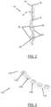
- the bipolar plate according to the invention is generally designated by the reference numeral 10.
- the bipolar plate here comprises a round, plate-shaped base body 12, which has a first main surface 14 and a second main surface 16 (see Figure 2 ).
- the first main surface 14 and the second main surface 16 extend parallel to each other.
- a first plurality of elevations 18 and a first plurality of depressions 20 are arranged on the first main surface 14 of the base body 10.
- a second plurality of elevations 22 and a second plurality of depressions 24 are arranged on the second main surface 16 of the base body 10 (see. Figure 2 ).
- a protrusion 18 defines on its inner side a depression 24 which is arranged on the second main surface 16.
- a protrusion 22 defines on its inner side a depression 20 which is arranged on the second main surface 16. This is because the bipolar plate 10 shown here is manufactured using an embossing process, so that pressing material into the first main surface 14 to create a depression 20 simultaneously creates a protrusion 22 on the second main surface 16.
- a depression 20 and a protrusion 18 on the first main surface 14 and a protrusion 22 and a depression 24 on the second main surface 16 are formed directly adjacent to one another as a pair 26.
- the bipolar plate 10 further comprises a fluid inlet 28 and a fluid outlet 30, which is positioned diametrically opposite the fluid inlet 24 with respect to the base body 12.
- the fluid inlet 28 and the fluid outlet 30 are indicated here by an oval ring.
- the fluid inlet 28 and the fluid outlet 30 can also be a region of the respective main surface 14, 16 into which a fluid passage opens through a cell frame (not shown) which surrounds the base body 12 of the bipolar plate 10.
- the first main surface 14 can have a fluid inlet 28 and a fluid outlet 30 and the second main surface 16 can have a separate fluid inlet (not shown) and a separate fluid outlet (not shown).
- a connecting line from the fluid inlet 28 to the fluid outlet 30 forms a main fluid flow direction X, which in Figure 1 coincides with the section line AA and is therefore only indicated by the arrow X attached to the section line AA.
- the main fluid flow direction X can be regarded as the first main fluid flow direction X and the main fluid flow direction of the connection of the second fluid inlet and the second fluid outlet on the second main surface 16 can be regarded as the second main fluid flow direction.
- FIG. 1 some of the elevations 18 on the first main surface 14 are grouped into a first elevation group 32 and some of the elevations 18 on the first main surface 14 are grouped into a second elevation group 34, wherein the first elevation group 32 is arranged closer to the fluid inlet 24 than the second elevation group 34.
- the lengths of the elevations 18 of the first elevation group 32 are arranged at an angle to the main fluid flow direction X such that an angle ⁇ formed therebetween is 45° or more, whereas the lengths of the elevations 18 of the second elevation group 34 are arranged at an angle to the main fluid flow direction X such that an angle ⁇ formed therebetween is less than 45° (here even 0°).
- the first elevation group 32 can thus Distribution of the fluid on the respective main surface 14.
- the second elevation group 34 can serve for the targeted alignment and discharge of the fluid towards the fluid outlet 26.
- FIG. 3 a second embodiment of a bipolar plate according to the invention can be seen in a perspective view, which is designated with the reference numeral 110.
- the second embodiment of the bipolar plate 110 features analogous to the first embodiment of the bipolar plate 10 are designated with analogous reference numerals, but increased by 100.
- the differences between the second embodiment of the bipolar plate 110 and the first embodiment of the bipolar plate 10 will therefore be discussed in detail.
- elevations 118 and depressions 120 are formed on the first main surface 114 that are analogous to the elevations 18, 22 and depressions 20, 24. However, the elevations 118 and depressions 120 on the first main surface 114 are spaced apart from one another, that is, they are not formed as a pair 26. As already described with reference to the bipolar plate 10, here too, the depressions 120 result in elevations on the second main surface, which is opposite the first main surface 114 and in Figure 3 Likewise, the elevations 118 form depressions on their inner side on the second main surface.
- the second embodiment of the bipolar plate 110 has beads 136 which surround respective elevations 118 (in the present case completely). This means that, when viewed from the main surface 114 towards the respective elevation 118, a depression formed by the bead is positioned in front of the elevation. This allows a certain displaceability of the elevation 118 in the height direction H to be achieved.
- FIG 4 represents a side cross-sectional view of a portion of a stack 38 according to the invention.
- the stack 38 comprises a first bipolar plate 10a and a second bipolar plate 10b, both of which are designed according to the bipolar plate 10 according to the invention, but mirrored to one another.
- the first bipolar plate 10a is arranged in the stack 38 relative to the second bipolar plate 10b in such a way that each elevation 18 of the first bipolar plate 10a is opposite an elevation 18 of the second bipolar plate 10b, viewed in the height direction H of a respective elevation 18 or in a normal direction to the main surfaces 14, 16 (cf. Figure 2 ) of the first bipolar plate 10a and/or the second bipolar plate 10b.
- This arrangement of the first bipolar plate 10a and the second bipolar plate 10b results in a mirror plane S which is arranged centrally between the two bipolar plates 10a and 10b.
- FIG 4 a separator 40 as well as a first electrode 42 and a second electrode 44 are shown.
- the separator 40 is arranged centrally between the two bipolar plates 10a and 10b (on the mirror plane S).
- the first electrode 42 is arranged on one side of the separator 40 and the second electrode 44 is arranged on the other side of the separator 40, so that an electrode-separator unit is formed.
- the stack 38 according to the invention can also be formed using two bipolar plates 110 mirrored to one another.
Landscapes
- Life Sciences & Earth Sciences (AREA)
- Engineering & Computer Science (AREA)
- Manufacturing & Machinery (AREA)
- Sustainable Development (AREA)
- Sustainable Energy (AREA)
- Chemical & Material Sciences (AREA)
- Chemical Kinetics & Catalysis (AREA)
- Electrochemistry (AREA)
- General Chemical & Material Sciences (AREA)
- Fuel Cell (AREA)
Applications Claiming Priority (1)
| Application Number | Priority Date | Filing Date | Title |
|---|---|---|---|
| DE102023110334 | 2023-04-24 |
Publications (1)
| Publication Number | Publication Date |
|---|---|
| EP4456209A1 true EP4456209A1 (fr) | 2024-10-30 |
Family
ID=90735087
Family Applications (1)
| Application Number | Title | Priority Date | Filing Date |
|---|---|---|---|
| EP24170537.5A Pending EP4456209A1 (fr) | 2023-04-24 | 2024-04-16 | Plaque bipolaire gaufrée |
Country Status (1)
| Country | Link |
|---|---|
| EP (1) | EP4456209A1 (fr) |
Cited By (1)
| Publication number | Priority date | Publication date | Assignee | Title |
|---|---|---|---|---|
| WO2026057439A1 (fr) * | 2024-09-16 | 2026-03-19 | Oberland Mangold Gmbh | Plaque bipolaire gaufrée |
Citations (4)
| Publication number | Priority date | Publication date | Assignee | Title |
|---|---|---|---|---|
| US20040038102A1 (en) * | 2000-09-23 | 2004-02-26 | Jorg Beckmann | Fuel cell stack |
| DE102022104250A1 (de) * | 2021-03-16 | 2022-09-22 | Schaeffler Technologies AG & Co. KG | Dünnblech und Verfahren zum Walzen von Dünnblech für eine elektrochemische Zelle |
| WO2022262894A1 (fr) * | 2021-06-16 | 2022-12-22 | Schaeffler Technologies AG & Co. KG | Plaque d'électrode d'une installation d'électrolyse |
| WO2023020647A1 (fr) * | 2021-08-18 | 2023-02-23 | Schaeffler Technologies AG & Co. KG | Plaque bipolaire et procédé pour produire une plaque bipolaire |
-
2024
- 2024-04-16 EP EP24170537.5A patent/EP4456209A1/fr active Pending
Patent Citations (4)
| Publication number | Priority date | Publication date | Assignee | Title |
|---|---|---|---|---|
| US20040038102A1 (en) * | 2000-09-23 | 2004-02-26 | Jorg Beckmann | Fuel cell stack |
| DE102022104250A1 (de) * | 2021-03-16 | 2022-09-22 | Schaeffler Technologies AG & Co. KG | Dünnblech und Verfahren zum Walzen von Dünnblech für eine elektrochemische Zelle |
| WO2022262894A1 (fr) * | 2021-06-16 | 2022-12-22 | Schaeffler Technologies AG & Co. KG | Plaque d'électrode d'une installation d'électrolyse |
| WO2023020647A1 (fr) * | 2021-08-18 | 2023-02-23 | Schaeffler Technologies AG & Co. KG | Plaque bipolaire et procédé pour produire une plaque bipolaire |
Cited By (2)
| Publication number | Priority date | Publication date | Assignee | Title |
|---|---|---|---|---|
| WO2026057439A1 (fr) * | 2024-09-16 | 2026-03-19 | Oberland Mangold Gmbh | Plaque bipolaire gaufrée |
| DE102024126587A1 (de) * | 2024-09-16 | 2026-03-19 | Oberland Mangold Gmbh | Geprägte Bipolarplatte |
Similar Documents
| Publication | Publication Date | Title |
|---|---|---|
| WO2018114819A1 (fr) | Plaque de séparation pour systeme électrochimique | |
| EP3350864B1 (fr) | Plaque de séparation pour système électrochimique | |
| DE202020103982U1 (de) | Bipolarplatte mit Schweissverbindungen | |
| DE102023203124A1 (de) | Separatorplatte und Verfahren zu ihrer Herstellung | |
| WO2023174482A1 (fr) | Plaque de champ d'écoulement et procédé de production d'une plaque de champ d'écoulement | |
| DE102008052945B4 (de) | Brennstoffzellenstapel und Verfahren zu dessen Herstellung | |
| DE102022203540A1 (de) | Separatorplatte mit homogenisierter sickenkraft im portbereich | |
| DE102022212601A1 (de) | Separatorplatte mit Schweißabschnitten | |
| DE102022116193B3 (de) | Bipolarplatte und Verfahren zur Herstellung einer Bipolarplatte | |
| DE102023132962A1 (de) | Separatorplatte mit einer Haltestruktur für einen Steckerstift | |
| DE102015223930A1 (de) | Bipolarplatte sowie Brennstoffzelle | |
| DE102022112175B3 (de) | Plattenanordnung für eine elektrochemische Zelle | |
| WO2024188698A1 (fr) | Plaque de champ d'écoulement et dispositif électrochimique comprenant une plaque de champ d'écoulement | |
| DE102023132353A1 (de) | Separatorplatte für ein elektrochemisches system mit einer entlastungssicke | |
| DE202023105024U1 (de) | Bipolarplatte für ein elektrochemisches System | |
| DE102024126587A1 (de) | Geprägte Bipolarplatte | |
| DE202022100690U1 (de) | Bipolarplatte und Brennstoffzelle | |
| DE102021108876B4 (de) | Elektrochemisches System | |
| WO2026067920A1 (fr) | Ensemble plaque pour un empilement de cellules électrochimiques et procédé de production d'un ensemble plaque | |
| DE102024117138A1 (de) | Elektrochemische Einheit und mehrere elektrochemische Einheiten umfassende elektrochemische Vorrichtung | |
| WO2025195804A1 (fr) | Élément de plaque bipolaire présentant une structure de perturbation d'écoulement | |
| DE102025100759A1 (de) | Elektrochemisches System mit Druckvergleichmäßigungsplatte | |
| WO2024260744A1 (fr) | Rouleau de gaufrage, son procédé de fabrication, plaque pour système électrochimique et procédé de fabrication d'une telle plaque | |
| DE202023105025U1 (de) | Separatorplatte für ein elektrochemisches System | |
| DE102022126790A1 (de) | Elektrochemische Vorrichtung |
Legal Events
| Date | Code | Title | Description |
|---|---|---|---|
| PUAI | Public reference made under article 153(3) epc to a published international application that has entered the european phase |
Free format text: ORIGINAL CODE: 0009012 |
|
| STAA | Information on the status of an ep patent application or granted ep patent |
Free format text: STATUS: THE APPLICATION HAS BEEN PUBLISHED |
|
| AK | Designated contracting states |
Kind code of ref document: A1 Designated state(s): AL AT BE BG CH CY CZ DE DK EE ES FI FR GB GR HR HU IE IS IT LI LT LU LV MC ME MK MT NL NO PL PT RO RS SE SI SK SM TR |
|
| STAA | Information on the status of an ep patent application or granted ep patent |
Free format text: STATUS: REQUEST FOR EXAMINATION WAS MADE |
|
| 17P | Request for examination filed |
Effective date: 20250415 |