EP4456214A1 - Dispositif électrochimique - Google Patents
Dispositif électrochimique Download PDFInfo
- Publication number
- EP4456214A1 EP4456214A1 EP23170282.0A EP23170282A EP4456214A1 EP 4456214 A1 EP4456214 A1 EP 4456214A1 EP 23170282 A EP23170282 A EP 23170282A EP 4456214 A1 EP4456214 A1 EP 4456214A1
- Authority
- EP
- European Patent Office
- Prior art keywords
- pressure
- fluid
- temperature
- electrochemical
- temperature gradient
- Prior art date
- Legal status (The legal status is an assumption and is not a legal conclusion. Google has not performed a legal analysis and makes no representation as to the accuracy of the status listed.)
- Withdrawn
Links
Images



Classifications
-
- H—ELECTRICITY
- H01—ELECTRIC ELEMENTS
- H01M—PROCESSES OR MEANS, e.g. BATTERIES, FOR THE DIRECT CONVERSION OF CHEMICAL ENERGY INTO ELECTRICAL ENERGY
- H01M8/00—Fuel cells; Manufacture thereof
- H01M8/04—Auxiliary arrangements, e.g. for control of pressure or for circulation of fluids
- H01M8/04298—Processes for controlling fuel cells or fuel cell systems
- H01M8/04694—Processes for controlling fuel cells or fuel cell systems characterised by variables to be controlled
- H01M8/04746—Pressure; Flow
- H01M8/04753—Pressure; Flow of fuel cell reactants
-
- C—CHEMISTRY; METALLURGY
- C25—ELECTROLYTIC OR ELECTROPHORETIC PROCESSES; APPARATUS THEREFOR
- C25B—ELECTROLYTIC OR ELECTROPHORETIC PROCESSES FOR THE PRODUCTION OF COMPOUNDS OR NON-METALS; APPARATUS THEREFOR
- C25B1/00—Electrolytic production of inorganic compounds or non-metals
- C25B1/01—Products
- C25B1/02—Hydrogen or oxygen
- C25B1/04—Hydrogen or oxygen by electrolysis of water
-
- C—CHEMISTRY; METALLURGY
- C25—ELECTROLYTIC OR ELECTROPHORETIC PROCESSES; APPARATUS THEREFOR
- C25B—ELECTROLYTIC OR ELECTROPHORETIC PROCESSES FOR THE PRODUCTION OF COMPOUNDS OR NON-METALS; APPARATUS THEREFOR
- C25B13/00—Diaphragms; Spacing elements
- C25B13/04—Diaphragms; Spacing elements characterised by the material
- C25B13/05—Diaphragms; Spacing elements characterised by the material based on inorganic materials
- C25B13/07—Diaphragms; Spacing elements characterised by the material based on inorganic materials based on ceramics
-
- C—CHEMISTRY; METALLURGY
- C25—ELECTROLYTIC OR ELECTROPHORETIC PROCESSES; APPARATUS THEREFOR
- C25B—ELECTROLYTIC OR ELECTROPHORETIC PROCESSES FOR THE PRODUCTION OF COMPOUNDS OR NON-METALS; APPARATUS THEREFOR
- C25B15/00—Operating or servicing cells
- C25B15/02—Process control or regulation
-
- C—CHEMISTRY; METALLURGY
- C25—ELECTROLYTIC OR ELECTROPHORETIC PROCESSES; APPARATUS THEREFOR
- C25B—ELECTROLYTIC OR ELECTROPHORETIC PROCESSES FOR THE PRODUCTION OF COMPOUNDS OR NON-METALS; APPARATUS THEREFOR
- C25B15/00—Operating or servicing cells
- C25B15/08—Supplying or removing reactants or electrolytes; Regeneration of electrolytes
-
- H—ELECTRICITY
- H01—ELECTRIC ELEMENTS
- H01M—PROCESSES OR MEANS, e.g. BATTERIES, FOR THE DIRECT CONVERSION OF CHEMICAL ENERGY INTO ELECTRICAL ENERGY
- H01M8/00—Fuel cells; Manufacture thereof
- H01M8/04—Auxiliary arrangements, e.g. for control of pressure or for circulation of fluids
- H01M8/04082—Arrangements for control of reactant parameters, e.g. pressure or concentration
- H01M8/04089—Arrangements for control of reactant parameters, e.g. pressure or concentration of gaseous reactants
- H01M8/04104—Regulation of differential pressures
-
- H—ELECTRICITY
- H01—ELECTRIC ELEMENTS
- H01M—PROCESSES OR MEANS, e.g. BATTERIES, FOR THE DIRECT CONVERSION OF CHEMICAL ENERGY INTO ELECTRICAL ENERGY
- H01M8/00—Fuel cells; Manufacture thereof
- H01M8/04—Auxiliary arrangements, e.g. for control of pressure or for circulation of fluids
- H01M8/04082—Arrangements for control of reactant parameters, e.g. pressure or concentration
- H01M8/04201—Reactant storage and supply, e.g. means for feeding, pipes
-
- H—ELECTRICITY
- H01—ELECTRIC ELEMENTS
- H01M—PROCESSES OR MEANS, e.g. BATTERIES, FOR THE DIRECT CONVERSION OF CHEMICAL ENERGY INTO ELECTRICAL ENERGY
- H01M8/00—Fuel cells; Manufacture thereof
- H01M8/04—Auxiliary arrangements, e.g. for control of pressure or for circulation of fluids
- H01M8/04298—Processes for controlling fuel cells or fuel cell systems
- H01M8/04313—Processes for controlling fuel cells or fuel cell systems characterised by the detection or assessment of variables; characterised by the detection or assessment of failure or abnormal function
- H01M8/0432—Temperature; Ambient temperature
- H01M8/04373—Temperature; Ambient temperature of auxiliary devices, e.g. reformers, compressors, burners
-
- H—ELECTRICITY
- H01—ELECTRIC ELEMENTS
- H01M—PROCESSES OR MEANS, e.g. BATTERIES, FOR THE DIRECT CONVERSION OF CHEMICAL ENERGY INTO ELECTRICAL ENERGY
- H01M8/00—Fuel cells; Manufacture thereof
- H01M8/04—Auxiliary arrangements, e.g. for control of pressure or for circulation of fluids
- H01M8/04298—Processes for controlling fuel cells or fuel cell systems
- H01M8/04313—Processes for controlling fuel cells or fuel cell systems characterised by the detection or assessment of variables; characterised by the detection or assessment of failure or abnormal function
- H01M8/0438—Pressure; Ambient pressure; Flow
-
- H—ELECTRICITY
- H01—ELECTRIC ELEMENTS
- H01M—PROCESSES OR MEANS, e.g. BATTERIES, FOR THE DIRECT CONVERSION OF CHEMICAL ENERGY INTO ELECTRICAL ENERGY
- H01M8/00—Fuel cells; Manufacture thereof
- H01M8/04—Auxiliary arrangements, e.g. for control of pressure or for circulation of fluids
- H01M8/04298—Processes for controlling fuel cells or fuel cell systems
- H01M8/04992—Processes for controlling fuel cells or fuel cell systems characterised by the implementation of mathematical or computational algorithms, e.g. feedback control loops, fuzzy logic, neural networks or artificial intelligence
-
- H—ELECTRICITY
- H01—ELECTRIC ELEMENTS
- H01M—PROCESSES OR MEANS, e.g. BATTERIES, FOR THE DIRECT CONVERSION OF CHEMICAL ENERGY INTO ELECTRICAL ENERGY
- H01M8/00—Fuel cells; Manufacture thereof
- H01M8/10—Fuel cells with solid electrolytes
- H01M8/12—Fuel cells with solid electrolytes operating at high temperature, e.g. with stabilised ZrO2 electrolyte
- H01M2008/1293—Fuel cells with solid oxide electrolytes
-
- H—ELECTRICITY
- H01—ELECTRIC ELEMENTS
- H01M—PROCESSES OR MEANS, e.g. BATTERIES, FOR THE DIRECT CONVERSION OF CHEMICAL ENERGY INTO ELECTRICAL ENERGY
- H01M8/00—Fuel cells; Manufacture thereof
- H01M8/04—Auxiliary arrangements, e.g. for control of pressure or for circulation of fluids
- H01M8/04298—Processes for controlling fuel cells or fuel cell systems
- H01M8/04313—Processes for controlling fuel cells or fuel cell systems characterised by the detection or assessment of variables; characterised by the detection or assessment of failure or abnormal function
- H01M8/0432—Temperature; Ambient temperature
-
- Y—GENERAL TAGGING OF NEW TECHNOLOGICAL DEVELOPMENTS; GENERAL TAGGING OF CROSS-SECTIONAL TECHNOLOGIES SPANNING OVER SEVERAL SECTIONS OF THE IPC; TECHNICAL SUBJECTS COVERED BY FORMER USPC CROSS-REFERENCE ART COLLECTIONS [XRACs] AND DIGESTS
- Y02—TECHNOLOGIES OR APPLICATIONS FOR MITIGATION OR ADAPTATION AGAINST CLIMATE CHANGE
- Y02E—REDUCTION OF GREENHOUSE GAS [GHG] EMISSIONS, RELATED TO ENERGY GENERATION, TRANSMISSION OR DISTRIBUTION
- Y02E60/00—Enabling technologies; Technologies with a potential or indirect contribution to GHG emissions mitigation
- Y02E60/30—Hydrogen technology
- Y02E60/36—Hydrogen production from non-carbon containing sources, e.g. by water electrolysis
-
- Y—GENERAL TAGGING OF NEW TECHNOLOGICAL DEVELOPMENTS; GENERAL TAGGING OF CROSS-SECTIONAL TECHNOLOGIES SPANNING OVER SEVERAL SECTIONS OF THE IPC; TECHNICAL SUBJECTS COVERED BY FORMER USPC CROSS-REFERENCE ART COLLECTIONS [XRACs] AND DIGESTS
- Y02—TECHNOLOGIES OR APPLICATIONS FOR MITIGATION OR ADAPTATION AGAINST CLIMATE CHANGE
- Y02E—REDUCTION OF GREENHOUSE GAS [GHG] EMISSIONS, RELATED TO ENERGY GENERATION, TRANSMISSION OR DISTRIBUTION
- Y02E60/00—Enabling technologies; Technologies with a potential or indirect contribution to GHG emissions mitigation
- Y02E60/30—Hydrogen technology
- Y02E60/50—Fuel cells
Definitions
- the invention relates to an electrochemical device and a method of controlling the electrochemical device according to the preamble of the independent claims.
- Reactant fluid control in electrochemical reactors such as fuel cells is common.
- the control of differential pressures of the fluids that flow through the reactor is of importance.
- Differential pressures can be tuned passively by means of, for example, diaphragms, liquid, spool valves, elastic tubes, stiff separation walls disposed between bellows, or expanding / contracting bodies that communicate with one or both reactant lines.
- An advantage of such passive control is that, in principle, it does not require any control logic.
- a potential downside is that this inherently minimizes the differential pressure between the reactants, which for some applications may not be feasible or preferred. This is why in particular applications the differential pressure is actively controlled, for example by means of controllable valves combined with pressure gauges and certain control logic.
- JP 2002-373682 A mentions differential pressure control in a fuel cell system by means of a regulator that acts on the differential pressure between the fuel and oxidant feed lines.
- JP 4,606,038 B2 discloses the usage of a controllable oxidant exhaust valve, in order to maintain underpressure of the oxidant at the exhaust side.
- a similar approach is disclosed in EP 2,108,199 B1 .
- a particular situation where exhaust differential pressure control is preferred is when exhaust streams are being used for recycling purposes, as disclosed in EP 3,432,399 B1 , or sent to devices located downstream the reactor that aim for additional fluid processing, and that create additional pressure drop of the fluid or create suction at the exhaust side of the reactor, as disclosed in US 10,727,508 B2 , EP 3,841,635 A1 and US 2021/399318 A1 .
- DE 10 2008 0107 11 B4 discloses a method to control the differential pressure of the reactant feed lines combined with control of the respective mass flows, using control logic such that the pressure of the fuel-bearing fluid and the oxygen-bearing fluid are coupled, and a change in the mass flow of at least one of the gases exerts no influence on the gas pressure of this gas.
- electrochemical reactors that operate at low temperature also depend on reactant control for keeping thermal gradients in the electrochemical reactor within acceptable limits.
- This can be achieved by preheating at least one of the fluids that are supplied to the reactor. For example, it can be done by preheating the oxygen-bearing fluid.
- this oxygen-bearing fluid provides oxidant to electrochemically oxidize the fuel-bearing fluid.
- oxygen-bearing fluid is often used as a sweep gas, for example to remove oxygen gas that is formed at the oxygen electrode.
- the presence of oxygen in the fuel-bearing fluid could irreversibly degrade the electrocatalyst that takes care of the electrochemical conversion reactions that take place in the fuel-bearing fluid, as well as catalyst located inside the electrochemical cell that is involved in gas conversion reactions such as reforming reactions or the water-gas shift reaction.
- the presence of oxygen in the fuel-bearing fluid could negatively affect the quality of the fuel-bearing fluid that leaves the electrochemical cell.
- Alteration of the fuel-bearing fluid due to mixing with oxygen-bearing fluid is particularly undesirable in case high system efficiency is aimed for, for example if the exhaust stream of the fuel-bearing fluid is being recycled to the cell inlet, or when there are specific requirements with respect to the chemical composition of the exhaust stream of the fuel-bearing fluid, for example if it is being processed in electrochemical cells located downstream the electrochemical cell, for example hydrogen purification cells or hydrogen pressurization cells, or if it is used in catalytic reactors, for example for the production of ammonia from a nitrogen stream and a hydrogen stream.
- a first aspect of the invention refers to an electrochemical device including:
- the device also comprises a control management system.
- the control management system is configured to keep a temperature gradient between the inlet side and the exhaust side of at least one fluid line below a predefined system critical temperature gradient and/or to control a minimum temperature and/or a maximum temperature across the electrochemical device compared with a pre-defined temperature reference.
- critical temperature refers to a temperature that could lead to damage or mechanical failure of the device during prolonged operation, and may be a device-specific temperature.
- the control management system can also be configured to keep a temperature gradient between the inlet and the exhaust side of both fluid lines below a predefined critical temperature.
- control management system is configured to control a differential pressure between the two fluid lines such that the fuel-bearing line is in overpressure relative to the oxygen-bearing line.
- the pressure can thus be controlled over the membrane of the cell.
- the differential pressure is preferably kept between pre-set boundaries, for example between 2 mbar and 30 mbar, where the pressure of the fuel-bearing fluid is in overpressure relative to the pressure of the oxygen-bearing fluid.
- control management system is configured to control the pressure drop of at least one fluid line within the electrochemical reactor, preferably both fluid lines, such that the pressure at the inlet side is higher than the pressure at the exhaust side and preferably the pressure drop of at least one fluid is kept between pre-set boundaries.
- the pre-set boundaries are preferably in the range between 0 and 650 mbar. This way, the losses associated with moving the fluid through the electrochemical reactor are kept within acceptable limits.
- pressure drop can also refer to "pressure differential between the fluid inlet side and fluid exhaust side” and should be distinguished from the pressure differential between two fluid lines.
- control management is configured to control at least one maximum pressure and/or at least one minimum pressure of a fluid in the electrochemical device compared to a pre-defined pressure reference.
- the pre-defined pressure reference can be ambient pressure, for example standard pressure of 1 bar.
- the pre-defined pressure may also be a pressure in a vessel of the device.
- the at least one maximum pressure and/or at least one minimum pressure is kept between pre-set boundaries.
- the minimum pressure for example, can be higher than 1 bar if the reference pressure is standard pressure of 1 bar.
- the maximum pressure can, for example, be set to a level where the reactor the reactor can be operated safely, or does not impose operational hazards to its circumference, for example 5 bar.
- the above-described device is particularly useful if the fuel-bearing fluid that leaves the electrochemical cell is being processed further downstream or is being recycled towards the inlet of the electrochemical reactor.
- the term fluid refers to either liquids or gases, but in particular gases.
- the fluid can function as reactant for fuel production.
- the fluid may also be sweep gas that removes emerging oxygen from the system, for example in the case of a solid oxide electrolyzer.
- the oxidant-bearing line may contain oxygen besides other components.
- the oxidant bearing line may contain air.
- the fuel-bearing line may contain fuel gases such as hydrogen or carbon monoxide, besides other gases such as steam or carbon dioxide.
- the control management system can be configured to prioritize differential pressure and/or maximum pressure and/or minimum pressure limits inside the device over temperature gradient limits such that a temperature gradient limit is exceedable.
- the temperature gradient within the electrochemical reactor is preferably kept below 75 ° C.
- the risk of failure of components inside the electrochemical reactor is thus low by model calculations that consider the calculation of local temperatures as function of the anticipated maximum electrolyte defect size throughout the operational lifetime as function of the local differential pressure between both reactant flows, supported by experimental observations.
- the temperature gradients within the electrochemical reactor are within an acceptable range to prevent detrimental failure of the electrochemical cells.
- the temperature gradient may increase to, for example, 100 ° C, at which point a corrective measure needs to take place until the temperature gradient is at maximum 75 ° C, whilst a limit for a pressure differential is kept.
- the maximum temperature limit can be 100 °C during a temporary overshoot. So, for the given case, the optimal is 75°C as explained above, allowing an overshoot of 25 °C.
- a device that adopts the proposed control scheme could include the following items.
- the device can comprise at least one flow controller disposed in at least one fluid line.
- the flow controller is connected or connectable to the control management system for controlling the mass flow of the fluid.
- a flow controller may be disposed in all fluid lines to control the mass flow of all fluids.
- the device can comprise pressure sensors to measure the pressure in the fluid lines, or differential pressure sensors to measure the differential pressure between the fluid lines, or pressure sensors to measure the pressure in the fluid line relative to the ambient pressure.
- the device can comprise temperature sensors to measure the temperature of at least one of the fluids.
- the device can comprise sensors to analyze the composition of at least one of the fluids that enters or leaves the reactor.
- the device Being equipped with a sufficient number of sensors, the device can be adequately controlled by, for example, one or more hysteresis loops.
- hysteresis loops could work independently, in sequence, or in a cascaded fashion, where one hysteresis loop receives feedback from another hysteresis loop.
- an operational mass flow and a preheat-temperature of the fluid are based on lookup tables; or are based on thermodynamic models, such as electrochemical, thermomechanical models, calculating a heat balance depending on the imposed operating conditions; or is based on real-time optimization routines or a data-driven model. This will allow for a reduction of the number of sensors that are required to control pressures and differential pressures inside the electrochemical reactor.
- data relating to the current state of the system can be obtained from sensors, the data can then be correlated to look up table or models and the operational mass flow and the preheat-temperature can be adjusted in order to ensure safe working of the electrochemical device.
- the pressure drop in an electrochemical reactor with planar electrochemical cells is directly proportional to the mass flow rate and the kinematic viscosity, i.e. the fluid's internal resistance to flow under gravitational forces, of the fluid, the latter being proportional to the pressure and proportional to the absolute temperature to the power 3/2, and dependent on the fluid composition.
- one or more lookup tables can be constructed, from which a targeted operational mass flow and a preheat-temperature of the fluid can be determined.
- the accuracy of the at least one lookup table is dependent on the level of detail that is included in the calculations. For example, in a simplified state, the at least one lookup table could rely on measured pressures and temperatures at the inlet side and the exhaust side of the electrochemical stack.
- the at least one lookup table could for example be based on the average mass flow rate, pressure and temperature that exist inside the electrochemical reactor, which depend on the operational state of the reactor, e.g. the conversion rates of the fluids due to the electrochemical reactions that take place during operation, the Joule heat associated with these electrochemical reactions, the heat capacity of the solid materials in the electrochemical stack, the specific heat capacity of the fluids, and the change in the fluid composition from the inlet side to the exhaust side.
- an operational mass flow and a preheat-temperature of the fluid are based on electrochemical or thermomechanical model.
- electrochemical or thermomechanical model Using the operational data imposed to the electrochemical reactor and data feedback from the electrochemical reactor, such models allow for calculating the distribution of the fluids, their associated compositions and pressures, the distribution of the temperatures within the electrochemical reactor, and the associated thermomechanical stress in the materials. This allows for accurate assessment of the pressures, differential pressures, and temperatures within the electrochemical reactor, by which the operational limits can be more accurately be guarded.
- the operational mass flow and the preheat-temperature are based on real-time optimization routines.
- the operational mass flow and the preheat-temperature is based on a data-driven model, such as an artificial neural network that, once trained with input and output data from a physical model or from previous experimental research, is able to estimate the output of the device depending on the actual input data without the need of a physical equation.
- a data-driven model such as an artificial neural network that, once trained with input and output data from a physical model or from previous experimental research, is able to estimate the output of the device depending on the actual input data without the need of a physical equation.
- the device can be trained with data from a physical model that is able to accurately predict the behaviour of the device under such conditions, or can be trained with data previously obtained with a representative device that was tested under such conditions.
- the pressure drop in an electrochemical reactor can be directly correlated to the mass flow rate and a kinematic viscosity of the fluid.
- the pressure drop can be proportional to the mass flow rate and a kinematic viscosity of the fluid, or may change dis-proportional.
- the electrochemical cell is an electrolyser cell or a fuel cell.
- the electrochemical cell can be a proton exchange membrane cell, a solid oxide cell, an alkaline cell or a molten-carbonate cell.
- the electrochemical cell is a cell that operates at elevated temperature, such as a solid oxide cell or a molten-carbonate cell.
- the electrochemical reactor that adopts one or more electrochemical cells is a reactor that allows for adoption of cells with electrolyte that is not fully gas-tight, such as a solid oxide cell with thin electrolyte, for example thinner than 20 micrometer, or cells with electrolyte that is prone to mechanical failure.
- a pressure control valve can be disposed within the at least one fluid line, preferably prior to or after the electrochemical reactor.
- a pressure control valve can also be disposed within both fluid lines. Pressure control valves can additionally help or backup a reliable working of the pressure control.
- controllable backpressure valves can be disposed in one of the fluid lines at the exhaust side or the electrochemical reactor.
- the pressure of the involved fluid is controlled depending on the pressure drop across the electrochemical reactor.
- the oxygen-bearing line can contain an oxygen-bearing gas, preferably air.
- the line can be supplied with oxygen bearing gas.
- the invention is by no means limited to the above description but could be used in different configurations as well.
- systems that use the preferred control scheme could be designed where electrochemical cells are classified based on their leak tightness or propensity to electrolyte mechanical failure, where those cells or cell classes that express the lowest gas tightness or highest failure risk are used where, for example, the risk of nickel oxidation or oxygen electrode degradation is the lowest.
- Such configurations are possible in, for example, systems with stacks that operate in cascade, systems with stacks that are operated at different temperatures, or stacks where more than one electrochemical cell, for example 2 or 4 cells, are integrated in each stack repeating element.
- a second aspect of the invention refers to a method of controlling an electrochemical device as previously described. The method comprising the steps of:
- the method can comprise step d): d) Measuring the differential pressure between a fuel-bearing line and an oxygen-bearing line and adjusting the differential pressure such that the fuel-bearing line is in overpressure to the oxygen-bearing line.
- the method can comprise step e): e) Measuring the pressure drop of at least one fluid line across the electrochemical reactor, wherein the pressure drop is adjusted to keep the pressure at the inlet side higher than the pressure at the exhaust side, and/or measuring the maximum and/or minimum pressure across the electrochemical cell compared to a pre-defined pressure reference and adjusting the pressure to predefined boundaries.
- the term pressure reference can refer to the ambient pressure surrounding the device.
- the pressure reference can be the pressure in a vessel of the device or a pressure in another component, fluid line or pipe, of the device.
- the method allows controlling a proper functioning of the device, failures due to exceeded pressure are drastically reduced.
- the method may work for an electrochemical cell where the cell is a fuel cell.
- the method is also applicable to cells or electrochemical reactors where the polarity is reversed, where fuel is produced by means of electric power, or any other operation that involves conversion of fluids and in particular reactants where intermixing should be kept as low as possible.
- At least one of the steps a) to e), preferably one of steps c) to d), is followed by: Determining a pressure drop within a fluid line and/or between fluid lines and/or maximum pressure and/or minimum pressure limits and temperature gradient limits and prioritizing the differential pressure limit such that the temperature gradient limit that is typical for steady-state operation is exceeded.
- the maximum temperature gradient limit is 100°C during a temporary overshoot.
- the optimal temperature gradient limit is 75°C, allowing an overshoot of 25 °C.
- the differential pressure can be changed in order to respect a temperature gradient limit for the steady-state operation.
- the temperature gradient can be kept below the defined system temperature gradient by controlling a mass flow and pre-heat temperature of the at least one fluid, in relation to the heat balance within the reactor.
- an operational mass flow and preheating of the at least one fluid are based on lookup tables, or are based on thermodynamic models calculating a heat balance depending on the imposed operating conditions, or are based on real-time optimization routines or are based on a data driven model.
- the pressure drop in an electrochemical reactor can be directly correlated to the mass flow rate and a kinematic viscosity of the fluid.
- a third aspect of the invention refers to a use of an electrochemical system as previously described for power and/or reactant and/or heat production.
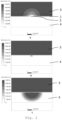
- the hydrogen concentration is shown, ranging from 10% hydrogen, 7% hydrogen, 1% hydrogen to 0% hydrogen, for a defect size (2) of 10 microns.
- a scale for the hydrogen amount is provided on the side of each figure corresponding to the above mentioned percentages. It can be seen that at +20 mbar differential pressure ( figure 1A ), fuel flows to the oxygen electrode (3) (top side of each graph). At 0 mbar differential pressure ( figure 1B ), air diffuses towards the fuel electrode (4). At -20 mbar differential pressure ( figure 1C , the oxygen electrode is at overpressure) air flows towards the fuel electrode (4), where in a considerable area the risk of nickel oxidation is high. An indication for the area that is at risk is marked by a hydrogen concentration in the fuel-air mixture with around 1 vol%, but even beyond that (down to a hydrogen concentration of 1 ppmv) nickel oxidation could occur.
- Table 1 summarizes the area where nickel oxidation may occur for all considered cases, estimating the area directly adjacent to the electrolyte, where air penetrates the farthest, as a function of the differential pressure for different defect sizes.
- the affected area was estimated by means of an isobar that is marking a hydrogen partial pressure of 3 vol% (used images not shown), within which the hydrogen partial pressure drops below this value due to the cross-over of air. From Table 1 it can be seen that the fuel electrode is at risk both at -10 and -20 mbar differential pressure (air in overpressure), but only for defect sizes greater than 2 microns. At equal pressure and at 1 mbar fuel overpressure, there is a small risk of anode oxidation for the largest defect size of 10 micron.
- the oxygen concentration is shown, again for a defect size (2) of 10 microns. It can be seen that at 20 mbar fuel overpressure (+20 mbar, figure 2A ), fuel flows to the oxygen electrode (3), causing a drop in the oxygen partial pressure. At equal pressure (0 mbar, figure 2B ), still some fuel diffuses to the oxygen electrode (3) as well as some air diffuses towards the fuel electrode. At 20 mbar air overpressure (-20 mbar, figure 2C ), air flows to the fuel electrode (4).
- Table 2 summarizes the area where oxygen electrode reduction may occur for all considered cases, estimating the area directly adjacent to the electrolyte, where fuel penetrates the farthest, as a function of the differential pressure for different defect sizes.
- the affected area was estimated by using graphs that indicates the area where the partial oxygen pressure is below 10E-5 atm, which is considered a boundary beyond which many mixed conducting perovskites that are used in oxygen electrodes for solid oxide cells, for example LSCF, become irreversibly unstable. From the table 2, it can be determined that the oxygen electrode is at risk at +20 mbar differential pressure, but only for a defect size of 10 microns. For smaller defects, and at lower fuel overpressures, there is no risk of oxygen electrode reduction.
- FIG 3 the steam concentration is shown, again for a defect size (2) of 10 microns. It can be seen that at 20 mbar fuel overpressure (+20 mbar, figure 3A ), steam concentrations up to 45% are present due to the flow of hydrogen-steam mixture to the oxygen electrode (3), where steam is formed due to combustion of hydrogen and due to the crossover from the fuel side. At equal pressure (0 mbar, figure 3B ), fuel diffuses to the oxygen electrode (3), but the concentrations of steam at the oxygen electrode (3) are lower.
- Table 3 summarizes the temperature overshoot in °C in the vicinity of a defect for all considered differential pressures. It can be seen that in all cases a temperature increase is observed, where the highest increase is observed for the highest fuel overpressure of +20 mbar and the largest defect size of 10 micron. TABLE 3: P diff 10 ⁇ m 5 ⁇ m 4 ⁇ m 2 ⁇ m 1 ⁇ m -20 mbar 11 6 4 2 2 -10 mbar 5 3 2 2 2 2 0 mbar 5 4 4 3 1 +1 mbar 6 5 4 3 1 +5 mbar 13 8 6 3 1 +20 mbar 43 21 15 5 2
- the control strategy is further elucidated by the four graphs. These graphs consider two cases. First, it will be explained how the reactor would respond without prioritising the pressure differential over temperature. This is shown by the curve that, upon reaching the second vertically dashed line, becomes dashed.
- the air flow shown in the third graph 5C is increased by means of a feedback loop that responds to the reactor temperature. Consequently, the air pressure will increase, causing a drop in the pressure differential, which drives towards a state where air is in overpressure of fuel (i.e. the pressure differential drops).
- the air flow is throttled at the point where the pressure differential reaches the minimum allowed pressure differential (in the graph this point is reached just before vertically dashed line 2), or at a safe margin above the minimum allowed pressure differential (not shown). This causes a temperature overshoot.
- the pressure differential is then increased by means of adjusting the back pressure to a value that will allow for a safe increase of the air flow, and the air flow is no longer throttled (marked by the shaded beam). It can be determined that the air flow increases further to let the reactor temperature arrive at a safe steady-state temperature. The increased air flow will once again cause a drop of the pressure differential, but now to a level that is still respecting a minimum allowed pressure differential (shown in the graph upon reaching vertically dashed line 4) or arrives at a value that keeps a safe margin above the minimum allowed pressure differential (not shown).
Landscapes
- Chemical & Material Sciences (AREA)
- Engineering & Computer Science (AREA)
- Chemical Kinetics & Catalysis (AREA)
- Electrochemistry (AREA)
- Life Sciences & Earth Sciences (AREA)
- Manufacturing & Machinery (AREA)
- Sustainable Development (AREA)
- Sustainable Energy (AREA)
- General Chemical & Material Sciences (AREA)
- Metallurgy (AREA)
- Materials Engineering (AREA)
- Organic Chemistry (AREA)
- Automation & Control Theory (AREA)
- Inorganic Chemistry (AREA)
- Evolutionary Computation (AREA)
- Health & Medical Sciences (AREA)
- Artificial Intelligence (AREA)
- Computing Systems (AREA)
- Ceramic Engineering (AREA)
- Fuzzy Systems (AREA)
- Medical Informatics (AREA)
- Software Systems (AREA)
- Theoretical Computer Science (AREA)
- Fuel Cell (AREA)
- Secondary Cells (AREA)
- Electrolytic Production Of Non-Metals, Compounds, Apparatuses Therefor (AREA)
- Hybrid Cells (AREA)
Priority Applications (8)
| Application Number | Priority Date | Filing Date | Title |
|---|---|---|---|
| EP23170282.0A EP4456214A1 (fr) | 2023-04-27 | 2023-04-27 | Dispositif électrochimique |
| CN202480026745.7A CN120981945A (zh) | 2023-04-27 | 2024-04-22 | 电化学装置 |
| AU2024263964A AU2024263964A1 (en) | 2023-04-27 | 2024-04-22 | Electrochemical device |
| PCT/EP2024/060885 WO2024223460A1 (fr) | 2023-04-27 | 2024-04-22 | Dispositif electrochimique |
| EP24719207.3A EP4702605A1 (fr) | 2023-04-27 | 2024-04-22 | Dispositif electrochimique |
| KR1020257032689A KR20260003661A (ko) | 2023-04-27 | 2024-04-22 | 전기화학 디바이스 |
| CL2025003255A CL2025003255A1 (es) | 2023-04-27 | 2025-10-23 | Dispositivo electroquímico. |
| MX2025012716A MX2025012716A (es) | 2023-04-27 | 2025-10-23 | Dispositivo electroquimico |
Applications Claiming Priority (1)
| Application Number | Priority Date | Filing Date | Title |
|---|---|---|---|
| EP23170282.0A EP4456214A1 (fr) | 2023-04-27 | 2023-04-27 | Dispositif électrochimique |
Publications (1)
| Publication Number | Publication Date |
|---|---|
| EP4456214A1 true EP4456214A1 (fr) | 2024-10-30 |
Family
ID=86271761
Family Applications (2)
| Application Number | Title | Priority Date | Filing Date |
|---|---|---|---|
| EP23170282.0A Withdrawn EP4456214A1 (fr) | 2023-04-27 | 2023-04-27 | Dispositif électrochimique |
| EP24719207.3A Pending EP4702605A1 (fr) | 2023-04-27 | 2024-04-22 | Dispositif electrochimique |
Family Applications After (1)
| Application Number | Title | Priority Date | Filing Date |
|---|---|---|---|
| EP24719207.3A Pending EP4702605A1 (fr) | 2023-04-27 | 2024-04-22 | Dispositif electrochimique |
Country Status (7)
| Country | Link |
|---|---|
| EP (2) | EP4456214A1 (fr) |
| KR (1) | KR20260003661A (fr) |
| CN (1) | CN120981945A (fr) |
| AU (1) | AU2024263964A1 (fr) |
| CL (1) | CL2025003255A1 (fr) |
| MX (1) | MX2025012716A (fr) |
| WO (1) | WO2024223460A1 (fr) |
Citations (13)
| Publication number | Priority date | Publication date | Assignee | Title |
|---|---|---|---|---|
| JP2002373682A (ja) | 2001-06-15 | 2002-12-26 | Honda Motor Co Ltd | 燃料電池システム |
| CN101479020A (zh) * | 2006-05-05 | 2009-07-08 | 普拉斯科能源Ip控股公司毕尔巴鄂-沙夫豪森分公司 | 气体调整系统 |
| JP4606038B2 (ja) | 2004-02-18 | 2011-01-05 | パナソニック株式会社 | 高分子電解質型燃料電池及びその運転方法 |
| EP2075866B1 (fr) | 2007-12-27 | 2011-06-08 | Nissan Motor Co., Ltd. | Syteme de pile à combustible |
| JP5231847B2 (ja) | 2008-03-31 | 2013-07-10 | 本田技研工業株式会社 | 燃料電池システム及びその運転方法 |
| EP2108199B1 (fr) | 2006-12-19 | 2015-02-18 | United Technologies Corporation | Contrôle de la pression de combustible mixte pour une pile à combustible |
| DE102008010711B4 (de) | 2008-02-21 | 2018-04-26 | Audi Ag | Verfahren zum Betreiben eines Brennstoffzellensystems sowie Brennstoffzellensystem mit einer Regleranordnung |
| US10727508B2 (en) | 2014-10-21 | 2020-07-28 | Audi Ag | Fuel cell system and method for switching off a fuel cell stack |
| EP3432399B1 (fr) | 2016-03-15 | 2021-01-27 | Nissan Motor Co., Ltd. | Système de pile à combustible et son dispositif de commande, et procédé de commande de système de pile à combustible |
| WO2021083625A1 (fr) | 2019-10-28 | 2021-05-06 | Haldor Topsøe A/S | Empilement de piles à oxyde solide avec une différence de pression entre des compartiments d'anode et de cathode |
| EP3841635A1 (fr) | 2018-08-21 | 2021-06-30 | Fuelcell Energy, Inc. | Pile à combustible avec protection contre un déséquilibre de pression |
| US20210399318A1 (en) | 2020-06-22 | 2021-12-23 | Fuelcell Energy, Inc. | System for rebalancing a pressure differential in a fuel cell using gas injection |
| CN114174661A (zh) * | 2019-05-21 | 2022-03-11 | 通用电气公司 | 具有底循环系统的闭式循环发动机 |
-
2023
- 2023-04-27 EP EP23170282.0A patent/EP4456214A1/fr not_active Withdrawn
-
2024
- 2024-04-22 EP EP24719207.3A patent/EP4702605A1/fr active Pending
- 2024-04-22 WO PCT/EP2024/060885 patent/WO2024223460A1/fr not_active Ceased
- 2024-04-22 AU AU2024263964A patent/AU2024263964A1/en active Pending
- 2024-04-22 KR KR1020257032689A patent/KR20260003661A/ko active Pending
- 2024-04-22 CN CN202480026745.7A patent/CN120981945A/zh active Pending
-
2025
- 2025-10-23 CL CL2025003255A patent/CL2025003255A1/es unknown
- 2025-10-23 MX MX2025012716A patent/MX2025012716A/es unknown
Patent Citations (13)
| Publication number | Priority date | Publication date | Assignee | Title |
|---|---|---|---|---|
| JP2002373682A (ja) | 2001-06-15 | 2002-12-26 | Honda Motor Co Ltd | 燃料電池システム |
| JP4606038B2 (ja) | 2004-02-18 | 2011-01-05 | パナソニック株式会社 | 高分子電解質型燃料電池及びその運転方法 |
| CN101479020A (zh) * | 2006-05-05 | 2009-07-08 | 普拉斯科能源Ip控股公司毕尔巴鄂-沙夫豪森分公司 | 气体调整系统 |
| EP2108199B1 (fr) | 2006-12-19 | 2015-02-18 | United Technologies Corporation | Contrôle de la pression de combustible mixte pour une pile à combustible |
| EP2075866B1 (fr) | 2007-12-27 | 2011-06-08 | Nissan Motor Co., Ltd. | Syteme de pile à combustible |
| DE102008010711B4 (de) | 2008-02-21 | 2018-04-26 | Audi Ag | Verfahren zum Betreiben eines Brennstoffzellensystems sowie Brennstoffzellensystem mit einer Regleranordnung |
| JP5231847B2 (ja) | 2008-03-31 | 2013-07-10 | 本田技研工業株式会社 | 燃料電池システム及びその運転方法 |
| US10727508B2 (en) | 2014-10-21 | 2020-07-28 | Audi Ag | Fuel cell system and method for switching off a fuel cell stack |
| EP3432399B1 (fr) | 2016-03-15 | 2021-01-27 | Nissan Motor Co., Ltd. | Système de pile à combustible et son dispositif de commande, et procédé de commande de système de pile à combustible |
| EP3841635A1 (fr) | 2018-08-21 | 2021-06-30 | Fuelcell Energy, Inc. | Pile à combustible avec protection contre un déséquilibre de pression |
| CN114174661A (zh) * | 2019-05-21 | 2022-03-11 | 通用电气公司 | 具有底循环系统的闭式循环发动机 |
| WO2021083625A1 (fr) | 2019-10-28 | 2021-05-06 | Haldor Topsøe A/S | Empilement de piles à oxyde solide avec une différence de pression entre des compartiments d'anode et de cathode |
| US20210399318A1 (en) | 2020-06-22 | 2021-12-23 | Fuelcell Energy, Inc. | System for rebalancing a pressure differential in a fuel cell using gas injection |
Also Published As
| Publication number | Publication date |
|---|---|
| CL2025003255A1 (es) | 2025-12-19 |
| MX2025012716A (es) | 2025-12-01 |
| KR20260003661A (ko) | 2026-01-07 |
| WO2024223460A1 (fr) | 2024-10-31 |
| EP4702605A1 (fr) | 2026-03-04 |
| CN120981945A (zh) | 2025-11-18 |
| AU2024263964A1 (en) | 2025-09-25 |
Similar Documents
| Publication | Publication Date | Title |
|---|---|---|
| Aguiar et al. | Anode-supported intermediate-temperature direct internal reforming solid oxide fuel cell: II. Model-based dynamic performance and control | |
| US8419910B2 (en) | Electrolyzer cell stack system | |
| US7353085B2 (en) | Electrolyzer cell stack system | |
| DE112019000300T5 (de) | Brennstoffzellensystem, Hybrid-Energieerzeugungssystem und Steuerverfahren für Brennstoffzellensystem | |
| US10622646B2 (en) | Fuel cell system and shutdown method thereof | |
| JP2001210346A (ja) | 燃料電池積層体を貫流する燃料流を確立する方法及び燃料電池システム | |
| WO2006054548A1 (fr) | Système de production d’énergie à pile à combustible, procédé et programme d’arrêt et de conservation | |
| US6696190B2 (en) | Fuel cell system and method | |
| EP4456214A1 (fr) | Dispositif électrochimique | |
| US20220231316A1 (en) | Fuel cell system | |
| US9917314B2 (en) | Mitigating electrode erosion in high temperature PEM fuel cell | |
| EP2124279A1 (fr) | Système de pile à combustible | |
| JP7108848B2 (ja) | 燃料電池システム | |
| JP2020009575A (ja) | 燃料電池システム並びにその運転方法 | |
| TWI897123B (zh) | 氫氣純化系統及其控制方法 | |
| Alizadeh et al. | Experimental study on a 1000W dead-end H2/O2 PEM fuel cell stack with cascade type for improving fuel utilization | |
| JP5135665B2 (ja) | 燃料電池システム | |
| Du Plooy et al. | Adaptive purging control of hydrogen fuel cells for high efficiency applications | |
| JP2007012548A (ja) | 燃料電池システム | |
| JP2006310182A (ja) | 燃料電池システム及びパージ弁制御方法 | |
| KR20220149084A (ko) | 수전해 시스템 및 그 제어 방법 | |
| US20250313974A1 (en) | Gas pressure controls for a water electrolyzer plant | |
| EP4570956A1 (fr) | Système électrochimique pour fonctionnement en mode de veille à haute température | |
| KR20260029968A (ko) | 수전해 시스템 및 이의 제어 방법 | |
| JPH07249423A (ja) | 燃料電池発電装置 |
Legal Events
| Date | Code | Title | Description |
|---|---|---|---|
| PUAI | Public reference made under article 153(3) epc to a published international application that has entered the european phase |
Free format text: ORIGINAL CODE: 0009012 |
|
| STAA | Information on the status of an ep patent application or granted ep patent |
Free format text: STATUS: THE APPLICATION HAS BEEN PUBLISHED |
|
| AK | Designated contracting states |
Kind code of ref document: A1 Designated state(s): AL AT BE BG CH CY CZ DE DK EE ES FI FR GB GR HR HU IE IS IT LI LT LU LV MC ME MK MT NL NO PL PT RO RS SE SI SK SM TR |
|
| STAA | Information on the status of an ep patent application or granted ep patent |
Free format text: STATUS: THE APPLICATION IS DEEMED TO BE WITHDRAWN |
|
| 18D | Application deemed to be withdrawn |
Effective date: 20250501 |