EP4456268A2 - Élément de batterie et procédé de fabrication d'un tel élément de batterie - Google Patents
Élément de batterie et procédé de fabrication d'un tel élément de batterie Download PDFInfo
- Publication number
- EP4456268A2 EP4456268A2 EP24169346.4A EP24169346A EP4456268A2 EP 4456268 A2 EP4456268 A2 EP 4456268A2 EP 24169346 A EP24169346 A EP 24169346A EP 4456268 A2 EP4456268 A2 EP 4456268A2
- Authority
- EP
- European Patent Office
- Prior art keywords
- cell
- contact element
- conductor
- battery cell
- bending
- Prior art date
- Legal status (The legal status is an assumption and is not a legal conclusion. Google has not performed a legal analysis and makes no representation as to the accuracy of the status listed.)
- Pending
Links
Images

Classifications
-
- H—ELECTRICITY
- H01—ELECTRIC ELEMENTS
- H01M—PROCESSES OR MEANS, e.g. BATTERIES, FOR THE DIRECT CONVERSION OF CHEMICAL ENERGY INTO ELECTRICAL ENERGY
- H01M50/00—Constructional details or processes of manufacture of the non-active parts of electrochemical cells other than fuel cells, e.g. hybrid cells
- H01M50/50—Current conducting connections for cells or batteries
- H01M50/531—Electrode connections inside a battery casing
-
- H—ELECTRICITY
- H01—ELECTRIC ELEMENTS
- H01M—PROCESSES OR MEANS, e.g. BATTERIES, FOR THE DIRECT CONVERSION OF CHEMICAL ENERGY INTO ELECTRICAL ENERGY
- H01M50/00—Constructional details or processes of manufacture of the non-active parts of electrochemical cells other than fuel cells, e.g. hybrid cells
- H01M50/50—Current conducting connections for cells or batteries
- H01M50/528—Fixed electrical connections, i.e. not intended for disconnection
-
- H—ELECTRICITY
- H01—ELECTRIC ELEMENTS
- H01M—PROCESSES OR MEANS, e.g. BATTERIES, FOR THE DIRECT CONVERSION OF CHEMICAL ENERGY INTO ELECTRICAL ENERGY
- H01M50/00—Constructional details or processes of manufacture of the non-active parts of electrochemical cells other than fuel cells, e.g. hybrid cells
- H01M50/10—Primary casings; Jackets or wrappings
- H01M50/102—Primary casings; Jackets or wrappings characterised by their shape or physical structure
- H01M50/103—Primary casings; Jackets or wrappings characterised by their shape or physical structure prismatic or rectangular
-
- H—ELECTRICITY
- H01—ELECTRIC ELEMENTS
- H01M—PROCESSES OR MEANS, e.g. BATTERIES, FOR THE DIRECT CONVERSION OF CHEMICAL ENERGY INTO ELECTRICAL ENERGY
- H01M10/00—Secondary cells; Manufacture thereof
- H01M10/04—Construction or manufacture in general
-
- H—ELECTRICITY
- H01—ELECTRIC ELEMENTS
- H01M—PROCESSES OR MEANS, e.g. BATTERIES, FOR THE DIRECT CONVERSION OF CHEMICAL ENERGY INTO ELECTRICAL ENERGY
- H01M50/00—Constructional details or processes of manufacture of the non-active parts of electrochemical cells other than fuel cells, e.g. hybrid cells
- H01M50/10—Primary casings; Jackets or wrappings
- H01M50/147—Lids or covers
- H01M50/148—Lids or covers characterised by their shape
- H01M50/15—Lids or covers characterised by their shape for prismatic or rectangular cells
-
- H—ELECTRICITY
- H01—ELECTRIC ELEMENTS
- H01M—PROCESSES OR MEANS, e.g. BATTERIES, FOR THE DIRECT CONVERSION OF CHEMICAL ENERGY INTO ELECTRICAL ENERGY
- H01M50/00—Constructional details or processes of manufacture of the non-active parts of electrochemical cells other than fuel cells, e.g. hybrid cells
- H01M50/10—Primary casings; Jackets or wrappings
- H01M50/147—Lids or covers
- H01M50/166—Lids or covers characterised by the methods of assembling casings with lids
-
- H—ELECTRICITY
- H01—ELECTRIC ELEMENTS
- H01M—PROCESSES OR MEANS, e.g. BATTERIES, FOR THE DIRECT CONVERSION OF CHEMICAL ENERGY INTO ELECTRICAL ENERGY
- H01M50/00—Constructional details or processes of manufacture of the non-active parts of electrochemical cells other than fuel cells, e.g. hybrid cells
- H01M50/40—Separators; Membranes; Diaphragms; Spacing elements inside cells
- H01M50/46—Separators, membranes or diaphragms characterised by their combination with electrodes
-
- H—ELECTRICITY
- H01—ELECTRIC ELEMENTS
- H01M—PROCESSES OR MEANS, e.g. BATTERIES, FOR THE DIRECT CONVERSION OF CHEMICAL ENERGY INTO ELECTRICAL ENERGY
- H01M50/00—Constructional details or processes of manufacture of the non-active parts of electrochemical cells other than fuel cells, e.g. hybrid cells
- H01M50/50—Current conducting connections for cells or batteries
- H01M50/531—Electrode connections inside a battery casing
- H01M50/533—Electrode connections inside a battery casing characterised by the shape of the leads or tabs
-
- H—ELECTRICITY
- H01—ELECTRIC ELEMENTS
- H01M—PROCESSES OR MEANS, e.g. BATTERIES, FOR THE DIRECT CONVERSION OF CHEMICAL ENERGY INTO ELECTRICAL ENERGY
- H01M50/00—Constructional details or processes of manufacture of the non-active parts of electrochemical cells other than fuel cells, e.g. hybrid cells
- H01M50/50—Current conducting connections for cells or batteries
- H01M50/531—Electrode connections inside a battery casing
- H01M50/536—Electrode connections inside a battery casing characterised by the method of fixing the leads to the electrodes, e.g. by welding
-
- H—ELECTRICITY
- H01—ELECTRIC ELEMENTS
- H01M—PROCESSES OR MEANS, e.g. BATTERIES, FOR THE DIRECT CONVERSION OF CHEMICAL ENERGY INTO ELECTRICAL ENERGY
- H01M50/00—Constructional details or processes of manufacture of the non-active parts of electrochemical cells other than fuel cells, e.g. hybrid cells
- H01M50/50—Current conducting connections for cells or batteries
- H01M50/531—Electrode connections inside a battery casing
- H01M50/54—Connection of several leads or tabs of plate-like electrode stacks, e.g. electrode pole straps or bridges
-
- H—ELECTRICITY
- H01—ELECTRIC ELEMENTS
- H01M—PROCESSES OR MEANS, e.g. BATTERIES, FOR THE DIRECT CONVERSION OF CHEMICAL ENERGY INTO ELECTRICAL ENERGY
- H01M50/00—Constructional details or processes of manufacture of the non-active parts of electrochemical cells other than fuel cells, e.g. hybrid cells
- H01M50/50—Current conducting connections for cells or batteries
- H01M50/543—Terminals
- H01M50/552—Terminals characterised by their shape
- H01M50/553—Terminals adapted for prismatic, pouch or rectangular cells
- H01M50/557—Plate-shaped terminals
-
- H—ELECTRICITY
- H01—ELECTRIC ELEMENTS
- H01M—PROCESSES OR MEANS, e.g. BATTERIES, FOR THE DIRECT CONVERSION OF CHEMICAL ENERGY INTO ELECTRICAL ENERGY
- H01M50/00—Constructional details or processes of manufacture of the non-active parts of electrochemical cells other than fuel cells, e.g. hybrid cells
- H01M50/50—Current conducting connections for cells or batteries
- H01M50/543—Terminals
- H01M50/564—Terminals characterised by their manufacturing process
- H01M50/566—Terminals characterised by their manufacturing process by welding, soldering or brazing
-
- Y—GENERAL TAGGING OF NEW TECHNOLOGICAL DEVELOPMENTS; GENERAL TAGGING OF CROSS-SECTIONAL TECHNOLOGIES SPANNING OVER SEVERAL SECTIONS OF THE IPC; TECHNICAL SUBJECTS COVERED BY FORMER USPC CROSS-REFERENCE ART COLLECTIONS [XRACs] AND DIGESTS
- Y02—TECHNOLOGIES OR APPLICATIONS FOR MITIGATION OR ADAPTATION AGAINST CLIMATE CHANGE
- Y02E—REDUCTION OF GREENHOUSE GAS [GHG] EMISSIONS, RELATED TO ENERGY GENERATION, TRANSMISSION OR DISTRIBUTION
- Y02E60/00—Enabling technologies; Technologies with a potential or indirect contribution to GHG emissions mitigation
- Y02E60/10—Energy storage using batteries
Definitions
- the invention relates to a battery cell according to the preamble of claim 1 and to a method for producing such a battery cell according to the preamble of claim 10.
- a prismatic battery cell has a cell stack inside the cell housing, i.e. an electrode/separator stack in which anodes and cathodes are arranged alternately one above the other in a stacking direction with separators in between.
- the anodes are extended laterally from the cell stack with anode-side conductor tabs, while the cathodes are extended laterally from the cell stack with cathode-side conductor tabs.
- the outer lateral ends of the anode-side conductor lugs are compacted into an anode-side conductor lug bundle, while the outer lateral ends of the cathode-side conductor lugs are compacted into a cathode-side conductor lug bundle.
- the anodes and cathodes each consist of a flexible substrate film that is coated with active material.
- the conductor lug is made of the same material and is an integral part of the substrate film.
- the arrester lugs protruding from the side of the cell stack have only a low inherent rigidity. This means that the arrester lugs are difficult to handle in the manufacturing process once they reach a certain length.
- the arrester lugs must therefore be dimensioned with a sufficiently short length; due to the short length, the arrester lug bundle is not in direct electrical contact with the cell terminal, but the arrester lug bundle is extended with a rigid contact element or a tab that can be electrically contacted with a corresponding cell terminal of the battery cell.
- a battery cell intermediate product is formed in which the composite of conductor lug bundle and contact element protrudes outwards transversely to a cell stack stacking direction with a projection from an open cell housing opening.
- a bending process is now carried out in which the composite consisting of a conductor lug bundle and a contact element is positioned in an assembly gap inside the housing between the cell stack and a wall element, in particular the cell housing base.
- a Z-fold is carried out during the bending process, in which contact element sections are folded together around a first bending point and the more flexible conductor lugs are also bent around a second bending point. Due to its comparatively high inherent rigidity, the contact element sections may only bend insufficiently during assembly or they spring back elastically. In this case, a contact element section close to the cell stack can damage or deform the flexible cell stack side.
- a battery cell in which several electrodes of a first polarity and several electrodes of a second polarity opposite to the first polarity are arranged in an electrode stack.
- the electrodes of the first polarity each have a first conductor lug that protrudes from the electrode stack on a first side of the electrode stack.
- the electrodes of the second polarity each have a second conductor lug that protrudes from the electrode stack on a second side of the electrode stack opposite the first.
- the object of the invention is to provide a battery cell and a method for producing such a battery cell, with the aid of which a perfect assembly of the battery cell can be carried out in comparison with the prior art.
- the invention is based on a battery cell with a cell housing in which a cell stack is arranged.
- a battery cell intermediate product is formed in which the cell stack is arranged in the housing interior and a conductor bundle formed from cell stack conductor tabs is extended with a contact element.
- the contact element can be electrically contacted with a cell terminal of the battery cell.
- the combination of conductor tab bundle and contact element protrudes transversely to a cell stack stacking direction with a projection from an open cell housing opening.
- the battery cell is assembled, in which the combination of conductor tab bundle and contact element is positioned in a mounting gap between the cell stack and a wall element in a bending process.
- the contact element which is particularly designed to be rigid, remains undeformed during the bending process, i.e. without bending.
- the conductor lugs which are particularly designed to be flexible, are deformed during the bending process. Since according to the invention only the conductor lugs are bent, but not the more rigid contact elements, damage or deformation of the more flexible cell stack side can be prevented. Such a deformation of the cell stack side would, however, occur if the more rigid contact element also had to be deformed by bending during the bending process. In this case, if the contact element is not bent sufficiently, an interference contour can be formed, by means of which the more flexible cell stack side can be deformed.
- the contact element can be connected to a cell terminal that is part of the wall element.
- the connection can be made in a material-locking manner, for example by ultrasonic welding or by gluing.
- the contact element can be made of two parts, namely a base sheet metal part and a separate additional sheet metal part.
- the base sheet metal part can be connected directly to the cell terminal.
- the base sheet metal part together with the additional sheet metal part can form a weld, in particular an ultrasonic weld, in which the arrester lug bundle is welded between the additional sheet metal part and the base sheet metal part.
- the ultrasonic welding tool is not brought into direct contact with the arrester lug bundle. Instead, the pressure is applied with the additional sheet metal part in between, so that damage to the arrester lug bundle can be prevented.
- the conductor lugs protrude from the side of the cell stack.
- the outer ends of the conductor lugs can be compacted into the conductor lug bundles in a pre-fixing step in which the conductor lug ends are stacked on top of each other in the stacking direction without gaps or air inclusions.
- the arrester lugs can have a bending axis or bending point in an area between the cell stack and the arrester lug bundle, around which the arrester lug bundle can be folded into the assembly gap during the bending process.
- the bending axis or bending point is defined in particular at the transition to the arrester lug bundle in the arrester lugs.
- a U-fold is carried out during the bending process, in which the contact element is folded over around the bending axis/bending point, namely with bending of the flexible arrester lugs around the bending axis, whereby the composite of contact element and arrester lug bundle can be positioned in the mounting gap inside the housing.
- the contact element connected to the cell terminal in the battery cell intermediate product has a smaller cross-section than the wall element.
- the contact element can be formed with an offset dimension within a wall element peripheral edge, which is positioned on an opening edge of the cell housing opening in the assembled state. With such a contact element geometry, the contact element can be positioned in the assembly gap inside the housing during assembly without interference contours and without deformation (without bending).
- FIGs 4 to 8 show a comparative example not covered by the invention.
- the battery cell has a cell stack 1 inside the cell housing, i.e. an electrode/separator stack, in which anodes and cathodes are arranged alternately one above the other in a stacking direction S with separator sheets in between.
- an anode A is indicated as an example. This is made of a flexible substrate film that is coated with active material. The substrate film is extended laterally outwards with an uncoated conductor lug 2.
- the cathodes which are not shown in detail, are constructed in the same way. In all figures, only the two outer conductor lugs 2 are shown from the large number of conductor lugs 2.
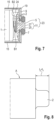
- FIG. 7 a cell stack side is shown from which all the anode-side conductor lugs 2 protrude laterally from the cell stack 1.
- the laterally outer conductor lug ends are compacted to form an anode-side conductor lug bundle 5.
- the conductor lug bundle 5 is not in direct electrical contact with a cell terminal 7, which is formed in a housing base 9 of the cell housing. Rather, the conductor lug bundle 5 is extended with a more rigid contact element 11, which is connected to the cell terminal 7. In this way, the conductor lugs 2 of the flexible anodes A can be provided with a reduced overall length I 2 ( Figure 8 ), which simplifies the handling of the arrester lugs 2 during battery production.
- the cell housing has a cuboid-shaped housing body 13. This consists of two opposite flat side walls 15, which are connected to each other via narrow side walls 17.
- the walls 15, 17 each delimit opposite cell housing openings 19, from which in the Figures 5 to 7 only one cell housing opening 19 is shown.
- the cell housing opening 19, not shown, is closed in the assembled state by a cover assembly, not shown, which consists of a housing cover, a cell terminal and a cell stack 1 electrically contacted thereto.
- a cover assembly not shown, which consists of a housing cover, a cell terminal and a cell stack 1 electrically contacted thereto.
- the opposite side shows the cell housing interior in the assembled state ( Figure 7 ) is closed by the housing bottom 9.
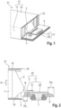
- the battery cell is shown at a process point before the assembly state as a battery cell intermediate product 21. Accordingly, the cover assembly (not shown) is already inserted into the housing body 13, while the housing base 9 is not yet completely mounted on the housing body 13. Rather, a composite 23 made up of conductor lug bundle 5 and contact element 11 protrudes outwards with a projection from the still open cell housing opening 19.
- the contact element 11 is in the Figures 5 to 7 as a two-layer sheet metal part. Its sheet metal layers 25, 27 are bent up on the side facing the cell stack 1, with the conductor lug bundle 5 being positioned between the two sheet metal layers 25, 27 of the contact element 11. The two sheet metal layers 25, 27 and the intermediate conductor lug bundle 5 are joined together in a material-locking manner by means of ultrasonic welding.
- the housing base 9 is positioned in a joining step on the opening edge area of the cell housing opening 19.
- the assembly 23 of the conductor lug bundle 5 and Contact element 11 in Z-fold around the bending points B1, B2 ( Figures 6 or 7 ) folded.
- the first bending point B1 divides the contact element 11 into a contact element section close to the cell stack and a contact element section far from the cell stack.
- the sheet metal layers 25, 27 of the contact element 11 protrude beyond the peripheral edge of the housing base 9 with an excess ⁇ x 2 . In this way, the overall length I 2 of the conductor lugs 2 can be shortened.
- the two contact element sections must be folded over one another around the bending point B1.
- the second bending point B2 is provided in the area of the arrester lugs 2 between the cell stack 1 and the arrester lug bundle 5 (directly at the transition to the arrester lug bundle 5).
- the contact element section far from the cell stack is first bent counterclockwise around the first bending point B1 relative to the contact element section close to the cell stack.
- the assembly 23 made up of the arrester lug bundle 5 and the contact element 11 is bent clockwise around the second bending point B2, whereby the assembly 23 can be inserted into an assembly gap 24 inside the housing between the cell stack 1 and the housing base 9.
- the contact element sections may only be insufficiently bent around the first bending point B1 during the bending process or they may spring back slightly elastically around the first bending point B1. In this case, the problem is that the contact element section close to the cell stack damages or deforms the flexible cell stack side.
- the contact element 11 remains undeformed during the bending process, i.e. without bending, while only the flexible conductor lugs 2 are deformed (i.e. bent) during the bending process.
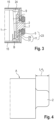
- the Figures 1 and 2 the contact element 11 connected to the cell terminal 7 - in contrast to the prior art - has a smaller cross-section than the Housing base 9.
- the contact element 11 is therefore offset by an amount ⁇ x 1 ( Figure 2 ) is set back from the peripheral edge of the housing base 9. In this way, the bending point B1 (comparative example, Figure 6 ) which is required to fold the cross-sectionally large contact element 11 for an assembly free of interference contours.
- the contact element 11 is made up of two parts, namely a base sheet part 29 and an additional sheet part 31.
- the base sheet part 29 is connected to the cell terminal 7.
- the additional sheet part 31 is firmly bonded to the base sheet part 29 by means of ultrasonic welding with the arrester lug bundle 5 in between.
Landscapes
- Chemical & Material Sciences (AREA)
- Chemical Kinetics & Catalysis (AREA)
- Electrochemistry (AREA)
- General Chemical & Material Sciences (AREA)
- Engineering & Computer Science (AREA)
- Manufacturing & Machinery (AREA)
- Connection Of Batteries Or Terminals (AREA)
- Sealing Battery Cases Or Jackets (AREA)
Applications Claiming Priority (1)
| Application Number | Priority Date | Filing Date | Title |
|---|---|---|---|
| DE102023203846 | 2023-04-26 |
Publications (2)
| Publication Number | Publication Date |
|---|---|
| EP4456268A2 true EP4456268A2 (fr) | 2024-10-30 |
| EP4456268A3 EP4456268A3 (fr) | 2025-01-15 |
Family
ID=90720412
Family Applications (1)
| Application Number | Title | Priority Date | Filing Date |
|---|---|---|---|
| EP24169346.4A Pending EP4456268A3 (fr) | 2023-04-26 | 2024-04-09 | Élément de batterie et procédé de fabrication d'un tel élément de batterie |
Country Status (6)
| Country | Link |
|---|---|
| US (1) | US20240363973A1 (fr) |
| EP (1) | EP4456268A3 (fr) |
| JP (1) | JP2024159664A (fr) |
| KR (1) | KR20240158170A (fr) |
| CN (1) | CN118867593A (fr) |
| CA (1) | CA3236184A1 (fr) |
Citations (1)
| Publication number | Priority date | Publication date | Assignee | Title |
|---|---|---|---|---|
| WO2020156951A1 (fr) | 2019-01-28 | 2020-08-06 | Bayerische Motoren Werke Aktiengesellschaft | Cellule d'accumulation d'énergie, module de batterie et procédé de fabrication |
Family Cites Families (4)
| Publication number | Priority date | Publication date | Assignee | Title |
|---|---|---|---|---|
| HUE061626T2 (hu) * | 2017-01-19 | 2023-07-28 | Bosch Gmbh Robert | Akkumulátor cella és eljárás annak elõállítására |
| WO2020066240A1 (fr) * | 2018-09-26 | 2020-04-02 | パナソニック株式会社 | Batterie secondaire |
| EP3712985A1 (fr) * | 2019-03-20 | 2020-09-23 | Manz AG | Procédé de fabrication d'un élément de batterie |
| JP7830495B2 (ja) * | 2021-10-08 | 2026-03-16 | ビークルエナジージャパン株式会社 | 電池及び電池の製造方法 |
-
2024
- 2024-04-09 EP EP24169346.4A patent/EP4456268A3/fr active Pending
- 2024-04-23 CA CA3236184A patent/CA3236184A1/en active Pending
- 2024-04-25 JP JP2024071860A patent/JP2024159664A/ja active Pending
- 2024-04-25 KR KR1020240055584A patent/KR20240158170A/ko active Pending
- 2024-04-25 CN CN202410504050.7A patent/CN118867593A/zh active Pending
- 2024-04-26 US US18/647,823 patent/US20240363973A1/en active Pending
Patent Citations (1)
| Publication number | Priority date | Publication date | Assignee | Title |
|---|---|---|---|---|
| WO2020156951A1 (fr) | 2019-01-28 | 2020-08-06 | Bayerische Motoren Werke Aktiengesellschaft | Cellule d'accumulation d'énergie, module de batterie et procédé de fabrication |
Also Published As
| Publication number | Publication date |
|---|---|
| CN118867593A (zh) | 2024-10-29 |
| JP2024159664A (ja) | 2024-11-08 |
| EP4456268A3 (fr) | 2025-01-15 |
| CA3236184A1 (en) | 2025-06-17 |
| KR20240158170A (ko) | 2024-11-04 |
| US20240363973A1 (en) | 2024-10-31 |
Similar Documents
| Publication | Publication Date | Title |
|---|---|---|
| DE102009023792B4 (de) | Verfahren zum einseitigen, einstufigen Fügen eines Metallblechstapels | |
| DE102010029682B4 (de) | Kartenrandverbinder und Verfahren für dessen Zusammenbau | |
| EP1483797B1 (fr) | Boitier cupuliforme et condensateur pourvu dudit boitier | |
| DE10003261B4 (de) | Aluminium-Elektrolyt-Kondensator | |
| DE112006002545T5 (de) | Gewickelter elektrischer Doppelschichtkondensator | |
| DE102018201155A1 (de) | Busbar | |
| DE102022000181A1 (de) | Elektrische Kontaktierung von Bauteilen und Batteriemodul | |
| DE10046885B4 (de) | Sekundärbatterie mit einer Vielzahl von durch einen Sammelanschluß verbundenen Elektrodenanschlüssen und Herstellungsverfahren dafür | |
| EP1506557A2 (fr) | Condensateur a puce et son procede de production | |
| DE112018005366T5 (de) | Energiespeichereinrichtung | |
| WO2011012202A1 (fr) | Batterie comprenant un empilement d'éléments de batterie unitaires bipolaires | |
| DE102012202623A1 (de) | Zellverbinder | |
| DE3909528A1 (de) | Stoerschutzfilter | |
| EP3232454B1 (fr) | Barre omnibus comprenant une pluralité de condensateurs à film | |
| EP4456268A2 (fr) | Élément de batterie et procédé de fabrication d'un tel élément de batterie | |
| EP2577757A1 (fr) | Composant multicouche piézoélectrique et procédé pour former une électrode extérieure sur un composant multicouche piézoélectrique | |
| WO2022194993A1 (fr) | Procédé de fabrication d'une chaîne de cellules solaires, chaîne de cellules solaires, dispositif de traitement pour une chaîne de cellules solaires, et utilisation d'un tel dispositif de traitement pour la fabrication d'une chaîne de cellules solaires | |
| DE102018205952B4 (de) | Zellwickel für eine Lithium-Ionen-Batteriezelle, Lithium-Ionen-Batteriezelle, Energiespeicher | |
| DE102014109176B4 (de) | Elektrische erdungsvorrichtung für ungleichartige metalle und verfahren zum herstellen einer elektrischen erdungsvorrichtung für ungleichartige metalle | |
| DE102024111281A1 (de) | Sekundärbatterie und batteriemodul | |
| DE102023115434A1 (de) | Flexibler Verbinder für Batteriezellen und Verfahren zum Verbinden von Batteriezellen sowie Batteriezellen-Anordnung | |
| WO2020020918A1 (fr) | Élément de batterie comprenant une pluralité d'électrodes et procédé de fabrication d'un élément de batterie | |
| DE102022112893A1 (de) | Batteriegehäuse und verfahren zur herstellung eines batteriegehäuses | |
| DE102015226143A1 (de) | Vielschichtaktor | |
| AT527918B1 (de) | Kollektor, sowie einen mit dem Kollektor ausgestatteter Akkumulatordeckel für einen Akkumulator |
Legal Events
| Date | Code | Title | Description |
|---|---|---|---|
| PUAI | Public reference made under article 153(3) epc to a published international application that has entered the european phase |
Free format text: ORIGINAL CODE: 0009012 |
|
| STAA | Information on the status of an ep patent application or granted ep patent |
Free format text: STATUS: THE APPLICATION HAS BEEN PUBLISHED |
|
| AK | Designated contracting states |
Kind code of ref document: A2 Designated state(s): AL AT BE BG CH CY CZ DE DK EE ES FI FR GB GR HR HU IE IS IT LI LT LU LV MC ME MK MT NL NO PL PT RO RS SE SI SK SM TR |
|
| PUAL | Search report despatched |
Free format text: ORIGINAL CODE: 0009013 |
|
| AK | Designated contracting states |
Kind code of ref document: A3 Designated state(s): AL AT BE BG CH CY CZ DE DK EE ES FI FR GB GR HR HU IE IS IT LI LT LU LV MC ME MK MT NL NO PL PT RO RS SE SI SK SM TR |
|
| RIC1 | Information provided on ipc code assigned before grant |
Ipc: H01M 50/46 20210101ALI20241211BHEP Ipc: H01M 50/566 20210101ALI20241211BHEP Ipc: H01M 50/557 20210101ALI20241211BHEP Ipc: H01M 50/54 20210101ALI20241211BHEP Ipc: H01M 50/536 20210101ALI20241211BHEP Ipc: H01M 50/533 20210101ALI20241211BHEP Ipc: H01M 50/528 20210101ALI20241211BHEP Ipc: H01M 50/166 20210101ALI20241211BHEP Ipc: H01M 50/15 20210101ALI20241211BHEP Ipc: H01M 50/103 20210101AFI20241211BHEP |
|
| RAP1 | Party data changed (applicant data changed or rights of an application transferred) |
Owner name: POWERCO SE |
|
| STAA | Information on the status of an ep patent application or granted ep patent |
Free format text: STATUS: REQUEST FOR EXAMINATION WAS MADE |
|
| 17P | Request for examination filed |
Effective date: 20250715 |