EP4456294A1 - Batterie, dispositif électrique et procédé de fabrication de batterie - Google Patents
Batterie, dispositif électrique et procédé de fabrication de batterie Download PDFInfo
- Publication number
- EP4456294A1 EP4456294A1 EP22954394.7A EP22954394A EP4456294A1 EP 4456294 A1 EP4456294 A1 EP 4456294A1 EP 22954394 A EP22954394 A EP 22954394A EP 4456294 A1 EP4456294 A1 EP 4456294A1
- Authority
- EP
- European Patent Office
- Prior art keywords
- battery
- battery cell
- box
- along
- side wall
- Prior art date
- Legal status (The legal status is an assumption and is not a legal conclusion. Google has not performed a legal analysis and makes no representation as to the accuracy of the status listed.)
- Pending
Links
Images


Classifications
-
- H—ELECTRICITY
- H01—ELECTRIC ELEMENTS
- H01M—PROCESSES OR MEANS, e.g. BATTERIES, FOR THE DIRECT CONVERSION OF CHEMICAL ENERGY INTO ELECTRICAL ENERGY
- H01M50/00—Constructional details or processes of manufacture of the non-active parts of electrochemical cells other than fuel cells, e.g. hybrid cells
- H01M50/20—Mountings; Secondary casings or frames; Racks, modules or packs; Suspension devices; Shock absorbers; Transport or carrying devices; Holders
- H01M50/258—Modular batteries; Casings provided with means for assembling
-
- H—ELECTRICITY
- H01—ELECTRIC ELEMENTS
- H01M—PROCESSES OR MEANS, e.g. BATTERIES, FOR THE DIRECT CONVERSION OF CHEMICAL ENERGY INTO ELECTRICAL ENERGY
- H01M50/00—Constructional details or processes of manufacture of the non-active parts of electrochemical cells other than fuel cells, e.g. hybrid cells
- H01M50/50—Current conducting connections for cells or batteries
- H01M50/502—Interconnectors for connecting terminals of adjacent batteries; Interconnectors for connecting cells outside a battery casing
- H01M50/507—Interconnectors for connecting terminals of adjacent batteries; Interconnectors for connecting cells outside a battery casing comprising an arrangement of two or more busbars within a container structure, e.g. busbar modules
-
- B—PERFORMING OPERATIONS; TRANSPORTING
- B60—VEHICLES IN GENERAL
- B60L—PROPULSION OF ELECTRICALLY-PROPELLED VEHICLES; SUPPLYING ELECTRIC POWER FOR AUXILIARY EQUIPMENT OF ELECTRICALLY-PROPELLED VEHICLES; ELECTRODYNAMIC BRAKE SYSTEMS FOR VEHICLES IN GENERAL; MAGNETIC SUSPENSION OR LEVITATION FOR VEHICLES; MONITORING OPERATING VARIABLES OF ELECTRICALLY-PROPELLED VEHICLES; ELECTRIC SAFETY DEVICES FOR ELECTRICALLY-PROPELLED VEHICLES
- B60L50/00—Electric propulsion with power supplied within the vehicle
- B60L50/50—Electric propulsion with power supplied within the vehicle using propulsion power supplied by batteries or fuel cells
- B60L50/60—Electric propulsion with power supplied within the vehicle using propulsion power supplied by batteries or fuel cells using power supplied by batteries
- B60L50/64—Constructional details of batteries specially adapted for electric vehicles
-
- H—ELECTRICITY
- H01—ELECTRIC ELEMENTS
- H01M—PROCESSES OR MEANS, e.g. BATTERIES, FOR THE DIRECT CONVERSION OF CHEMICAL ENERGY INTO ELECTRICAL ENERGY
- H01M10/00—Secondary cells; Manufacture thereof
- H01M10/60—Heating or cooling; Temperature control
- H01M10/61—Types of temperature control
- H01M10/613—Cooling or keeping cold
-
- H—ELECTRICITY
- H01—ELECTRIC ELEMENTS
- H01M—PROCESSES OR MEANS, e.g. BATTERIES, FOR THE DIRECT CONVERSION OF CHEMICAL ENERGY INTO ELECTRICAL ENERGY
- H01M10/00—Secondary cells; Manufacture thereof
- H01M10/60—Heating or cooling; Temperature control
- H01M10/62—Heating or cooling; Temperature control specially adapted for specific applications
- H01M10/625—Vehicles
-
- H—ELECTRICITY
- H01—ELECTRIC ELEMENTS
- H01M—PROCESSES OR MEANS, e.g. BATTERIES, FOR THE DIRECT CONVERSION OF CHEMICAL ENERGY INTO ELECTRICAL ENERGY
- H01M10/00—Secondary cells; Manufacture thereof
- H01M10/60—Heating or cooling; Temperature control
- H01M10/64—Heating or cooling; Temperature control characterised by the shape of the cells
- H01M10/647—Prismatic or flat cells, e.g. pouch cells
-
- H—ELECTRICITY
- H01—ELECTRIC ELEMENTS
- H01M—PROCESSES OR MEANS, e.g. BATTERIES, FOR THE DIRECT CONVERSION OF CHEMICAL ENERGY INTO ELECTRICAL ENERGY
- H01M10/00—Secondary cells; Manufacture thereof
- H01M10/60—Heating or cooling; Temperature control
- H01M10/65—Means for temperature control structurally associated with the cells
- H01M10/655—Solid structures for heat exchange or heat conduction
- H01M10/6556—Solid parts with flow channel passages or pipes for heat exchange
-
- H—ELECTRICITY
- H01—ELECTRIC ELEMENTS
- H01M—PROCESSES OR MEANS, e.g. BATTERIES, FOR THE DIRECT CONVERSION OF CHEMICAL ENERGY INTO ELECTRICAL ENERGY
- H01M10/00—Secondary cells; Manufacture thereof
- H01M10/60—Heating or cooling; Temperature control
- H01M10/65—Means for temperature control structurally associated with the cells
- H01M10/656—Means for temperature control structurally associated with the cells characterised by the type of heat-exchange fluid
-
- H—ELECTRICITY
- H01—ELECTRIC ELEMENTS
- H01M—PROCESSES OR MEANS, e.g. BATTERIES, FOR THE DIRECT CONVERSION OF CHEMICAL ENERGY INTO ELECTRICAL ENERGY
- H01M50/00—Constructional details or processes of manufacture of the non-active parts of electrochemical cells other than fuel cells, e.g. hybrid cells
- H01M50/20—Mountings; Secondary casings or frames; Racks, modules or packs; Suspension devices; Shock absorbers; Transport or carrying devices; Holders
- H01M50/204—Racks, modules or packs for multiple batteries or multiple cells
-
- H—ELECTRICITY
- H01—ELECTRIC ELEMENTS
- H01M—PROCESSES OR MEANS, e.g. BATTERIES, FOR THE DIRECT CONVERSION OF CHEMICAL ENERGY INTO ELECTRICAL ENERGY
- H01M50/00—Constructional details or processes of manufacture of the non-active parts of electrochemical cells other than fuel cells, e.g. hybrid cells
- H01M50/20—Mountings; Secondary casings or frames; Racks, modules or packs; Suspension devices; Shock absorbers; Transport or carrying devices; Holders
- H01M50/204—Racks, modules or packs for multiple batteries or multiple cells
- H01M50/207—Racks, modules or packs for multiple batteries or multiple cells characterised by their shape
- H01M50/209—Racks, modules or packs for multiple batteries or multiple cells characterised by their shape adapted for prismatic or rectangular cells
-
- H—ELECTRICITY
- H01—ELECTRIC ELEMENTS
- H01M—PROCESSES OR MEANS, e.g. BATTERIES, FOR THE DIRECT CONVERSION OF CHEMICAL ENERGY INTO ELECTRICAL ENERGY
- H01M50/00—Constructional details or processes of manufacture of the non-active parts of electrochemical cells other than fuel cells, e.g. hybrid cells
- H01M50/20—Mountings; Secondary casings or frames; Racks, modules or packs; Suspension devices; Shock absorbers; Transport or carrying devices; Holders
- H01M50/244—Secondary casings; Racks; Suspension devices; Carrying devices; Holders characterised by their mounting method
-
- H—ELECTRICITY
- H01—ELECTRIC ELEMENTS
- H01M—PROCESSES OR MEANS, e.g. BATTERIES, FOR THE DIRECT CONVERSION OF CHEMICAL ENERGY INTO ELECTRICAL ENERGY
- H01M50/00—Constructional details or processes of manufacture of the non-active parts of electrochemical cells other than fuel cells, e.g. hybrid cells
- H01M50/20—Mountings; Secondary casings or frames; Racks, modules or packs; Suspension devices; Shock absorbers; Transport or carrying devices; Holders
- H01M50/249—Mountings; Secondary casings or frames; Racks, modules or packs; Suspension devices; Shock absorbers; Transport or carrying devices; Holders specially adapted for aircraft or vehicles, e.g. cars or trains
-
- H—ELECTRICITY
- H01—ELECTRIC ELEMENTS
- H01M—PROCESSES OR MEANS, e.g. BATTERIES, FOR THE DIRECT CONVERSION OF CHEMICAL ENERGY INTO ELECTRICAL ENERGY
- H01M50/00—Constructional details or processes of manufacture of the non-active parts of electrochemical cells other than fuel cells, e.g. hybrid cells
- H01M50/20—Mountings; Secondary casings or frames; Racks, modules or packs; Suspension devices; Shock absorbers; Transport or carrying devices; Holders
- H01M50/271—Lids or covers for the racks or secondary casings
-
- H—ELECTRICITY
- H01—ELECTRIC ELEMENTS
- H01M—PROCESSES OR MEANS, e.g. BATTERIES, FOR THE DIRECT CONVERSION OF CHEMICAL ENERGY INTO ELECTRICAL ENERGY
- H01M50/00—Constructional details or processes of manufacture of the non-active parts of electrochemical cells other than fuel cells, e.g. hybrid cells
- H01M50/20—Mountings; Secondary casings or frames; Racks, modules or packs; Suspension devices; Shock absorbers; Transport or carrying devices; Holders
- H01M50/289—Mountings; Secondary casings or frames; Racks, modules or packs; Suspension devices; Shock absorbers; Transport or carrying devices; Holders characterised by spacing elements or positioning means within frames, racks or packs
-
- H—ELECTRICITY
- H01—ELECTRIC ELEMENTS
- H01M—PROCESSES OR MEANS, e.g. BATTERIES, FOR THE DIRECT CONVERSION OF CHEMICAL ENERGY INTO ELECTRICAL ENERGY
- H01M50/00—Constructional details or processes of manufacture of the non-active parts of electrochemical cells other than fuel cells, e.g. hybrid cells
- H01M50/50—Current conducting connections for cells or batteries
-
- H—ELECTRICITY
- H01—ELECTRIC ELEMENTS
- H01M—PROCESSES OR MEANS, e.g. BATTERIES, FOR THE DIRECT CONVERSION OF CHEMICAL ENERGY INTO ELECTRICAL ENERGY
- H01M50/00—Constructional details or processes of manufacture of the non-active parts of electrochemical cells other than fuel cells, e.g. hybrid cells
- H01M50/50—Current conducting connections for cells or batteries
- H01M50/502—Interconnectors for connecting terminals of adjacent batteries; Interconnectors for connecting cells outside a battery casing
- H01M50/503—Interconnectors for connecting terminals of adjacent batteries; Interconnectors for connecting cells outside a battery casing characterised by the shape of the interconnectors
-
- H—ELECTRICITY
- H01—ELECTRIC ELEMENTS
- H01M—PROCESSES OR MEANS, e.g. BATTERIES, FOR THE DIRECT CONVERSION OF CHEMICAL ENERGY INTO ELECTRICAL ENERGY
- H01M10/00—Secondary cells; Manufacture thereof
- H01M10/05—Accumulators with non-aqueous electrolyte
- H01M10/052—Li-accumulators
- H01M10/0525—Rocking-chair batteries, i.e. batteries with lithium insertion or intercalation in both electrodes; Lithium-ion batteries
-
- H—ELECTRICITY
- H01—ELECTRIC ELEMENTS
- H01M—PROCESSES OR MEANS, e.g. BATTERIES, FOR THE DIRECT CONVERSION OF CHEMICAL ENERGY INTO ELECTRICAL ENERGY
- H01M2220/00—Batteries for particular applications
- H01M2220/20—Batteries in motive systems, e.g. vehicle, ship, plane
-
- H—ELECTRICITY
- H01—ELECTRIC ELEMENTS
- H01M—PROCESSES OR MEANS, e.g. BATTERIES, FOR THE DIRECT CONVERSION OF CHEMICAL ENERGY INTO ELECTRICAL ENERGY
- H01M50/00—Constructional details or processes of manufacture of the non-active parts of electrochemical cells other than fuel cells, e.g. hybrid cells
- H01M50/50—Current conducting connections for cells or batteries
- H01M50/502—Interconnectors for connecting terminals of adjacent batteries; Interconnectors for connecting cells outside a battery casing
-
- H—ELECTRICITY
- H01—ELECTRIC ELEMENTS
- H01M—PROCESSES OR MEANS, e.g. BATTERIES, FOR THE DIRECT CONVERSION OF CHEMICAL ENERGY INTO ELECTRICAL ENERGY
- H01M50/00—Constructional details or processes of manufacture of the non-active parts of electrochemical cells other than fuel cells, e.g. hybrid cells
- H01M50/50—Current conducting connections for cells or batteries
- H01M50/502—Interconnectors for connecting terminals of adjacent batteries; Interconnectors for connecting cells outside a battery casing
- H01M50/509—Interconnectors for connecting terminals of adjacent batteries; Interconnectors for connecting cells outside a battery casing characterised by the type of connection, e.g. mixed connections
-
- Y—GENERAL TAGGING OF NEW TECHNOLOGICAL DEVELOPMENTS; GENERAL TAGGING OF CROSS-SECTIONAL TECHNOLOGIES SPANNING OVER SEVERAL SECTIONS OF THE IPC; TECHNICAL SUBJECTS COVERED BY FORMER USPC CROSS-REFERENCE ART COLLECTIONS [XRACs] AND DIGESTS
- Y02—TECHNOLOGIES OR APPLICATIONS FOR MITIGATION OR ADAPTATION AGAINST CLIMATE CHANGE
- Y02E—REDUCTION OF GREENHOUSE GAS [GHG] EMISSIONS, RELATED TO ENERGY GENERATION, TRANSMISSION OR DISTRIBUTION
- Y02E60/00—Enabling technologies; Technologies with a potential or indirect contribution to GHG emissions mitigation
- Y02E60/10—Energy storage using batteries
Definitions
- the present application relates to the technical field of batteries, and more particularly to a battery, an electrical apparatus and a battery forming method.
- the output member connected to the main output terminal of the battery group is usually arranged across the entire battery, which causes problems of increased weight and cost.
- the present application provides a battery, an electrical apparatus and a battery forming method.
- the battery can avoid arranging an output member across the entire battery, thereby reducing the weight and cost.
- a battery including a box, battery groups, a busbar, and two output members.
- the battery group is arranged in the box.
- the number of battery groups is two or more and they are arranged along a first direction.
- Each battery group includes an even number of battery cells arranged along a second direction perpendicular to the first direction.
- the battery cell includes a first side wall and a second side wall connected to each other.
- the first side wall is the wall with the largest area among all the outer walls of the battery cell.
- the first direction is perpendicular to the first side wall.
- the second side walls of two adjacent battery cells are arranged opposite to each other along the second direction.
- the busbar is used to electrically connect two adjacent battery cells.
- the two output members are arranged on the same side of the first direction.
- the outermost battery group along the first direction is provided with two output terminals distributed along the second direction.
- the two output members are electrically connected to the two output terminals respectively to form a power supply path together with the busbar.
- the two output members and the two output terminals of the battery face the same side, which can simplify the connection structure, improve the space utilization inside the box, facilitate processing and assembly, while avoiding use of a long output member across the battery group to form a power supply path, reducing the weight and cost, and improving the integration and energy density of the battery.
- the busbar includes a plurality of first busbars and a plurality of second busbars.
- the first busbars are used to electrically connect two adjacent battery cells along the first direction
- the second busbars are used to electrically connect two adjacent battery cells along the second direction.
- the busbars can be assembled regularly, improving the assembly efficiency, and ensuring the effectiveness of forming two output terminals on the outermost battery group in the first direction, thereby ensuring that the two output members are arranged on the same side of the first direction, so as to improve the space utilization inside the box, reduce the weight and cost, and improve the integration and energy density of the battery.
- the second busbar is used to electrically connect two adjacent battery cells in the outermost battery group along the first direction.
- the two output terminals are respectively arranged on the two battery cells located at the ends in the second direction in the outermost battery group, which reduces the arrangement length of the two output members, thereby reducing the weight and cost and improving the integration and energy density of the battery.
- the battery further includes a position-limiting member fixedly connected inside the box and abutting against the first side wall of the battery cell.
- the position-limiting member is used to limit the deformation of the battery cell in the first direction.
- the position-limiting member can provide positioning for the battery cell, which is beneficial to the installation efficiency and installation accuracy, thereby ensuring desirable quality of the battery. Moreover, the position-limiting member can limit the deformation of the battery cell in the first direction, which can buffer the expansion of the battery cell and ensure the safety performance of the battery.
- the battery cell further includes an output member base arranged on the position-limiting member to support the output member.
- the output member and the output member base form an output interface for connection with external electrical apparatus, which facilitates the installation and fixation of the output member, avoids contact short circuits, and ensures the safety performance of the battery.
- the position-limiting member extends along the second direction and is connected to the box at both ends in the second direction, which can improve the overall structural strength of the box, improve the ability to resist expansion of the battery cells, and ensure safety performance.
- the position-limiting member abuts against the first side wall of the battery cell in the outermost battery group, which can provide positioning for the battery group, which is beneficial to installation efficiency and installation accuracy, thereby ensuring desirable quality of the battery.
- a plurality of cavities penetrating along the second direction are provided in the position-limiting member.
- the space inside the cavities can be compressed in the first direction so that the position-limiting member can limit the deformation of the battery cell and buffer and absorb the expansion force of the battery cell, thereby ensuring the safety performance of the battery cell.
- the provision of the cavities can also reduce the weight of the position-limiting member, reduce the costs, and achieve a lightweight design, while improving the overall energy density of the battery.
- a partition is provided between two adjacent battery groups along the first direction and abuts against the first side wall of each battery cell in the two adj acent battery groups.
- the partition can serve as a structural member of the box.
- the partition By sandwiching the partition between two adjacent battery groups and connecting it to the first side wall of each battery cell, the partition can better achieve at least one of the functions of improving structural strength and resisting expansion force.
- the partition is adhered and fixed to the first side wall of each battery cell in two adjacent battery groups.
- the partition and each battery cell are integrally connected by adhesion, so that the partition and each battery cell of the battery group can be integrally adhered and then placed into the box as a whole, which facilitates the assembly of batteries into groups and also makes adjacent battery groups be arranged more compact to improve the space utilization efficiency of the box.
- the partition is used to regulate the temperature of the battery cell, and a medium flow channel is provided in the partition.
- the partition can not only perform thermal management of the battery cells, but also serve as a structural member of the box to improve the overall structural strength of the battery, thus eliminating the need for horizontal and vertical beams arranged inside the box, resulting in high integration and reduced cost, improving space utilization of the box, and achieving a lightweight design.
- the battery further includes a communication channel, an inlet pipe and an outlet pipe, the medium flow channels of the partitions are in communication through the communication channel, and the inlet pipe and the outlet pipe are in communication with the medium flow channel of the same partition.
- each partition can meet the demand for heat exchange medium through only one inlet pipe and one outlet pipe, reducing the space occupation, and simplifying the structure of the inlet pipe and outlet pipe, which facilitates assembly and replacement, and is applicable to the supply of heat exchange medium for different numbers of partitions, thereby improving flexibility and versatility.
- the box includes a top cover, a bottom cover and an accommodating frame.
- the bottom cover and the top cover are arranged opposite to each other at two ends of the accommodating frame in the height direction of the box.
- the position-limiting member is respectively connected to the accommodating frame and at least one of the top cover and the bottom cover.
- the box further includes a connection seat protruding from the accommodating frame along the second direction, and the connection seat is used to install the battery on the electrical apparatus.
- connection seat By arranging the connection seat, the connection and fixation of the entire battery in the electrical apparatus to which it is applied is facilitated, thereby ensuring the safety performance of the battery.
- the battery cell includes an electrode terminal, and along the height direction, the surface of the battery cell facing away from the electrode terminal is connected to the top cover or the bottom cover.
- the battery cells can be placed vertically in the box, or placed upside down in the box, which can improve the selectivity of battery manufacturing and forming.
- embodiments of the present application provide an electrical apparatus including the battery in any of the aforementioned implementations, so that the electrical apparatus can operate normally.
- embodiments of the present application provide a battery forming method, including: providing an even number of battery cells, the battery cells including a first side wall and a second side wall, the first side wall being the wall with the largest area among all the outer walls of the battery cell; dividing a plurality of battery cells into groups, each group including an even number of battery cells, and arranging the second side walls of the battery cells in the same group opposite to each other to form two or more battery groups; stacking the two or more battery groups and placing them into the box as a whole; electrically connecting the battery cells in the battery groups via a busbar; and providing two output members and arranging them on the same side of the first direction, where the two output members are electrically connected respectively to the two output terminals provided on the outermost battery group along the first direction, and the two output terminals are distributed along the second direction to form a power supply path together with the busbar.
- the battery manufactured by this forming method is convenient for processing and assembly, and can avoid use of a long output member across the battery group to form a power supply path, thereby reducing the weight and cost, and improving the integration and energy density of the battery.
- the technical terms “mount,” “join,” “connect,” “fix,” etc. should be understood in a broad sense, such as, a fixed connection, a detachable connection, or an integral connection; a mechanical connection, or an electrical connection; a direct connection, an indirect connection through an intermediate medium, an internal connection of two elements, or interaction between two elements.
- the specific meanings of the above terms in the embodiments of the present application can be understood according to specific situations.
- a first feature being “on” or “under” a second feature may be a case that the first feature is in direct contact with the second feature, or the first feature is in indirect contact with the second feature via an intermediate medium.
- the expression the first feature being “over,” “above” and “on top of” the second feature may be a case that the first feature is directly above or obliquely above the second feature, or only means that the level of the first feature is higher than that of the second feature.
- first feature being "below”, “underneath” or “under” the second feature may represent the case where the first feature is directly underneath or obliquely underneath the second feature, or only means that the level of the first feature is lower than that of the second feature.
- power batteries are more and more widely used.
- the power batteries are used in energy storage power source systems such as hydraulic, thermal, wind and solar power stations as well as in electric vehicles such as electric bicycles, electric motorcycles and electric cars, and military equipment and aerospace fields. With the continuous expansion of the application field of the power batteries, the market demand is also constantly expanding.
- existing batteries usually include a plurality of battery cells.
- a plurality of connecting pieces need to be provided between the battery cells for electrical connection, and a long connecting piece needs to be provided to form the main output terminal.
- this arrangement will cause a complicated structure of arrangement of connecting pieces in the battery, is not beneficial for processing and assembly, and will also increase weight and cost.
- the applicant designed a battery after in-depth research, including a box, a battery group, a busbar and two output members.
- the battery group is arranged in the box.
- the number of battery groups is two or more and they are arranged along a first direction.
- Each battery group includes an even number of battery cells arranged along a second direction perpendicular to the first direction.
- the battery cell includes a first side wall and a second side wall connected to each other.
- the first side wall is the wall with the largest area among all the outer walls of the battery cell.
- the first direction is perpendicular to the first side wall.
- the second side walls of two adjacent battery cells are arranged opposite to each other along the second direction.
- the busbar is used to electrically connect two adjacent battery cells.
- the two output members are arranged on the same side of the first direction.
- the outermost battery group along the first direction is provided with two output terminals distributed along the second direction.
- the two output members are electrically connected respectively to the two output terminals to form a power supply path together with the busbar.
- the battery group is placed inside the box to meet sealing requirements.
- the busbar is used to electrically connect two adjacent battery cells.
- the outermost battery group along the first direction is provided with two output terminals.
- the two output members are provided on the same side of the first direction.
- the two output members are electrically connected respectively to the two output terminals to form a power supply path together with the busbar.
- the two output members and the two output terminals face the same side, which can simplify the connection structure, improve the space utilization inside the box, and facilitate processing and assembly, while avoiding use of a long output member across the battery group to form a power supply path, reducing the weight and cost, and improving the compactness and energy density of the battery cell.
- the electrical apparatus may be, but not limited to, a vehicle, a mobile phone, a portable device, a laptop computer, a ship, a spacecraft, an electric toy, an electric tool, and the like.
- the vehicle may be a fuel vehicle, a gas vehicle or a new energy vehicle.
- the new energy vehicle may be an all-electric vehicle, a hybrid electric vehicle, an extended-range vehicle, or the like.
- the spacecraft includes airplanes, rockets, space shuttles, spaceships, and the like.
- the electric toy includes fixed or mobile electric toys, such as game consoles, electric car toys, electric ship toys, electric aircraft toys, and the like.
- the electric tool includes metal cutting electric tools, grinding electric tools, assembly electric tools and railway electric tools, such as electric drills, electric grinders, electric wrenches, electric screwdrivers, electric hammers, impact drills, concrete vibrators, electric planers, and the like.
- the electrical apparatus is not specially limited in the embodiments of the present application.
- the vehicle 1000 may be a fuel vehicle, a gas vehicle, or a new energy vehicle, and the new energy vehicle may be an all-electric vehicle, a hybrid electric vehicle, an extended-range electric vehicle, or the like.
- the vehicle 1000 is provided with a battery 100 inside, and the battery 100 may be provided at the bottom or head or tail of the vehicle 1000.
- the battery 100 may be used to power the vehicle 1000.
- the battery 100 may serve as an operating power source of the vehicle 1000.
- the vehicle 1000 may further include a controller 200 and a motor 300.
- the controller 200 is used to control the battery 10 to power the motor 300, for example, for meeting the operating power demand when the vehicle 1000 is starting, navigating and traveling.
- the battery 100 not only may serve as an operating power source of the vehicle 1000, but also as a driving power source of the vehicle 1000, thus replacing or partially replacing fuel or natural gas to provide driving power for the vehicle 1000.
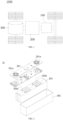
- an embodiment of the present application provides a battery 100, including a box 10, a battery group 20, a busbar 30 and two output members 40.
- the battery group 20 is arranged in the box 10.
- the number of the battery groups 20 is two or more and they are arranged along a first direction X.
- Each battery group 20 includes an even number of battery cells 21 arranged in a second direction Y
- the second direction Y is perpendicular to the first direction X.
- the battery cells 21 include a first side wall 211 and a second side wall 212 connected to each other.
- the first side wall 211 is the wall with the largest area among all the outer walls of the battery cell 21.
- the first direction X is perpendicular to the first side wall 211.
- the second side walls 212 of two adjacent battery cells 21 are arranged opposite to each other along the second direction Y
- the busbar 30 is used to electrically connect two adjacent battery cells 21.
- the two output members 40 are arranged on the same side of the first direction X.
- the outermost battery group 21 along the first direction X is provided with two output terminals distributed along the second direction Y
- the two output members 40 are electrically connected respectively to the two output terminals to form a power supply path together with the busbar 30.
- the second direction Y is perpendicular to the first direction X.
- the first direction X may be the length direction of the box 10, and accordingly, the second direction Y is the width direction of the box 10.
- the first direction X may also be the width direction of the box 10, and accordingly, the second direction Y is the length direction of the box 10.
- the box 10 may be a simple three-dimensional structure such as a single cuboid or a cylinder, or a complex three-dimensional structure composed of simple three-dimensional structures such as a cuboid or a cylinder.
- the embodiments of the present application are not limiting in this regard.
- the box 10 may be made of alloy materials such as aluminum alloy, iron alloy, etc., or polymer materials such as polycarbonate, polyisocyanurate foam, or composite materials such as glass fiber plus epoxy resin.
- alloy materials such as aluminum alloy, iron alloy, etc.
- polymer materials such as polycarbonate, polyisocyanurate foam, or composite materials such as glass fiber plus epoxy resin.
- the embodiments of the present application are not limiting in this regard either.
- the box 10 is used to accommodate the battery cells 21.
- the box 10 may be of various structures, as long as the sealing requirements are ensured.
- the number of the battery groups 20 is two or more and they are arranged along the first direction X.
- Each battery group 20 includes an even number of battery cells 21 arranged along the second direction Y
- the number of the battery cells 21 may be two, four, six, eight, ten or multiple battery cells may be provided, as long as the number of the battery cells 21 is an even number. If there are multiple battery cells 21, the multiple battery cells 21 can be connected in series, in parallel, or in a hybrid pattern along the second direction Y to form a battery group 20, and multiple battery groups 20 can then be connected in series, in parallel, or in a hybrid pattern along the first direction X to form a whole body that is accommodated in the box 10.
- the hybrid connection means that the multiple battery cells 21 are both connected in series and in parallel.
- the battery cell 21 may include a lithium ion battery cell 21, a sodium ion battery cell 21, a magnesium ion battery cell 21, or the like, and the embodiments of the present application are not limiting in this regard.
- the battery cell 21 may be flat, cuboid, or in other shapes, and the embodiments of the present application are not limiting in this regard either.
- the battery cells 21 are generally classified into three types according to their packaging manners: cylindrical battery cells 21, cubic prismatic battery cells 21, and pouch battery cells 21, and the embodiments of the present application are not limiting in this regard either. However, for the sake of simplicity of description, the following embodiments take the cubic prismatic battery cell 21 as an example.
- the battery cell 21 refers to the smallest unit that constitutes the battery 100.
- the battery cell 21 includes an end cap assembly 201, a case 202 and an electrode assembly 203.
- the end cap assembly 201 is a component that covers the opening of the case 202 to isolate the internal environment of the battery cell 21 from the external environment.
- the shape of the end cap assembly 201 may be adapted to that of the case 202 in order to fit the case 202.
- the end cap 201 may be made of a material with a certain hardness and strength (such as aluminum alloy). In this way, the end cap assembly 201 is less likely to deform when subjected to squeezing and collision, so that the battery cell 21 can have higher structural strength and improved safety performance as well.
- the end cap assembly 201 may be provided with functional components such as electrode terminals 201a.
- the electrode terminal 201a may be used to be electrically connected with the electrode assembly 203 for outputting or inputting electrical energy of the battery cell 21.
- the end cap assembly 201 may also be provided with a pressure relief mechanism to relieve pressure inside the battery cell when internal pressure or temperature of the battery cell 21 reaches a threshold.
- the end cap assembly 201 may be made of various materials, such as copper, iron, aluminum, stainless steel, aluminum alloy, and plastic, and the embodiments of the present application are not specifically limiting in this regard.
- an insulating member may also be provided on the inner side of the end cap assembly 201, and the insulating member may be used to isolate the electrical connection components in the case 202 from the end cap assembly 201 to reduce the risk of short circuits.
- the insulating member may be plastic, rubber, and the like.
- the case 202 is a component to cooperate with the end cap assembly 201 to form an internal environment of the battery cell 21.
- the internal environment formed can be used to accommodate the electrode assembly 203, electrolyte (not shown in the drawings), and other components.
- the case 202 and the end cap assembly 201 may be independent components, and an opening may be provided on the case 202.
- the end cap assembly 201 covers the opening at the opening to form the internal environment of the battery cell 21.
- the end cap assembly 201 and the case 202 can also be integrated.
- the end cap assembly 201 and the case 202 can form a common connection surface before other components are placed in the case. When the interior of the case 202 needs to be packaged, the end cap assembly 201 is then enabled to cover the case 202.
- the case 202 may be of various shapes and sizes, such as a cuboid shape. Specifically, the shape of the case 202 may be determined according to the specific shape and dimension and size of the electrode assembly 203.
- the case 202 may be made of various materials, such as copper, iron, aluminum, stainless steel, aluminum alloy, and plastic, and the embodiments of the present application are not specifically limiting in this regard.
- the electrode assembly 203 is a component in which electrochemical reaction occurs in the battery cell 21.
- One or more electrode assemblies 203 may be contained in the case 202.
- the electrode assembly 203 is mainly formed by winding or stacking a positive electrode plate and a negative electrode plate, and usually a separator is provided between the positive electrode plate and the negative electrode plate.
- the portions of the positive electrode plate and the negative electrode plate that contain active material constitute the main body of the electrode assembly 203, and the portions of the positive electrode plate and the negative electrode plate without active material each constitute tabs.
- the positive electrode tab 203a and the negative electrode tab 203b may be located together at one end of the main body or located respectively at two ends of the main body.
- the battery 100 provided by the embodiments of the present application also includes a busbar 30 and two output members 40.
- the busbar 30 is used to electrically connect two adjacent battery cells 21.
- the two output members 40 are provided on the same side of the first direction X.
- the outermost battery group 20 along the first direction X is provided with two output terminals distributed along the second direction Y.
- the two output terminals 40 are electrically connected respectively to the two output terminals to form a power supply path together with the busbar 30.
- the two output members 40 and the two output terminals of the battery 100 face the same side, which can simplify the connection structure, improve the space utilization inside the box 10, facilitate processing and assembly, while avoiding use of a long output member 40 across the battery group 20 to form a power supply path, reducing the weight and cost, and improving the compactness and energy density of the battery cell 21.
- two adjacent battery cells 21 can be electrically connected via the busbar 30.
- the busbar 30 can be connected to the electrode terminals 201a on the adjacent battery cells 21, so that the multiple battery cells 21 in the same battery group 20 or two adjacent battery groups 20 are connected in series, in parallel or in a hybrid pattern.
- the outermost battery group 20 along the first direction X is provided with two output terminals to ensure that the two output members 40 can be arranged on the same side of the first direction, so as to simplify the structure and improve the space utilization inside the box 10.
- the busbar 30 may be made of any one material of aluminum, copper, iron or the like.
- the output member 40 may be made of any one material of aluminum, copper, iron or the like.
- the output member 40 may be integrally formed through a stamping process, or be integrally formed by casting.
- the two output terminals are distributed along the second direction Y, so that the two output members 40 are spaced apart in the second direction Y, thereby avoiding safety problems such as short circuit caused by contact between adjacent output members 40, and ensuring the safety performance of the battery 100.
- the number of battery cells 21 included in each battery group 20 is an even number.
- the number of battery cells 21 included in each battery group 20 can be set to 4.
- the number can also be set to 6, or as shown in Fig. 6 , it can be set to 8.
- the busbar 30 electrically connects two adjacent battery cells 21, it can be ensured that the two output terminals are formed on the outermost battery group 20 along the first direction X and are distributed along the second direction Y, thus ensuring that the two output members 40 are provided on the same side of the first direction X, so as to avoid use of a long output member 40 across the battery group 20 to form a power supply path, reduce the weight and cost, and improve the compactness and energy density of the battery cell 21.
- the battery 100 provided in the embodiments of the present application is provided with two output members 40 that are electrically connected to the two output terminals respectively.
- the two output terminals are located in the outermost battery group 20 along the first direction X and are distributed along the second direction Y, so that the two output members 40 are provided on the same side of the first direction X, which can simplify the connection structure, improve the space utilization inside the box 10, facilitate processing and assembly, while avoiding use of a long output member 40 across the battery group 20 to form a power supply path, reducing the weight and cost, and improving the integration and energy density of the battery 100.
- the battery 100 provided in the embodiment of the present application adopts the above structural form.
- the second side walls 212 of the even number of battery cells 21 can be arranged opposite to each other along the second direction Y to form the battery group 20.
- Multiple battery groups 20 are arranged along the first direction X.
- Two adjacent battery cells 21 are electrically connected via the busbar 30 and two output terminals are formed in the outermost battery group 20 along the first direction X and are distributed along the second direction Y
- Two output members 40 are further provided to be electrically connected to the two output terminals respectively, so as to form a power supply path together with the busbar 30.
- the busbar 30 includes a plurality of first busbars 31 and a plurality of second busbars 32.
- the first busbars 31 are used to electrically connect two adjacent battery cells 21 along the first direction X
- the second busbars 32 are used to electrically connect two adjacent battery cells 21 along the second direction Y
- the busbars 30 can be assembled regularly, improving the assembly efficiency, and ensuring the effectiveness of forming two output terminals on the outermost battery group 20 in the first direction X, thereby ensuring that the two output members 40 are arranged on the same side of the first direction X.
- the first busbar 31 can electrically connect the electrode terminals 201a on adjacent battery cells 21 in the first direction X to realize series, parallel or hybrid connection of multiple battery cells 21 in the same battery group 20.
- the second busbar 32 can electrically connect the electrode terminals 201a on adjacent battery cells 21 in the second direction Y to realize series, parallel or hybrid connection of multiple battery cells 21 in two adjacent battery groups 20.
- the second busbar 32 is used to electrically connect two adjacent battery cells 21 in the outermost battery group 20 along the first direction X.
- the two output terminals are respectively provided on the two battery cells 21 located at the ends along the second direction in the outermost battery group 20.
- the length of the two output members 40 can be reduced, which can reduce the weight and cost, and improve the integration and energy density of the battery 100.
- the battery 100 further includes a position-limiting member 50 fixedly connected inside the box 10 and abutting against the first side wall 211 of the battery cell 21.
- the position-limiting member 50 is used to limit the deformation of the battery cell 21 in the first direction X.
- the position-limiting member 50 is provided to limit the deformation of the battery cell 21 in the first direction X so as to protect the operation safety of the battery cell 21 and thus ensure the safety performance of the battery 100. Moreover, it can provide positioning for the battery group 20, which facilitates the accurate and rapid installation of the battery group 20 at the preset position in the box 10, avoids deviation during installation that prevents other components from being installed accurately, and improves the installation efficiency and installation accuracy, thereby ensuring desirable quality of the battery 100.
- the position-limiting member 50 and the box 10 may be of an integrally formed structure and be formed through processes such as bending and stamping.
- the position-limiting member 50 and the box 10 may also be provided separately, and then integrally connected through welding, adhesion, or the like.
- the number of position-limiting members 50 may be one or two, and of course, multiple position-limiting members may be provided.
- the position-limiting member 50 can limit the expansion and deformation of the battery cell 21 in the first direction X to protect the safe operation of the battery cell 21 and consequently ensures the safety performance of the battery 100.
- the ratio of the height of the position-limiting member 50 to the height of the battery cell 21 can be set between 2/3 and 11/10, including the two end values of 2/3 and 11/10, which can not only provide the structural strength and expansion resistance effects, but also save space and improve space utilization.
- the battery 100 further includes an output member base 60 arranged on the position-limiting member 50 to support the output member 40.
- the output base 60 includes insulating material.
- the number of output member bases 60 may be one or two, and of course, multiple output member bases may be provided.
- the position-limiting member 50 is provided with an accommodating groove 51, and the output member base 60 at least partially extends into the accommodating groove 51.
- the accommodating groove 51 can limit the position of the output member base 60 to prevent its displacement that causes safety problems for the battery 100, while providing positioning effects to facilitate the installation of the output member base 60 and improve the manufacturing efficiency.
- the number of accommodating grooves 51 may be one or two, and of course, multiple accommodating grooves may be provided.
- the shape of the accommodating groove 51 can be set to match that of the output member base 60, and the output member base 60 can fit exactly into the accommodating groove 51 so that its position can be limited and prevented from displacement.
- the output member bases 60 and the accommodating grooves 51 can be arranged in one-to-one correspondence in their numbers, or in multiple-to-one correspondence in their numbers, that is, multiple output member bases 60 can be arranged in the same accommodating groove 51.
- the position-limiting member 50 is provided with two or more accommodating grooves 51, and the two or more accommodating grooves 51 are spaced apart.
- the accommodating grooves 51 can be formed by stamping, so that the accommodating grooves 51 can be quickly formed on the position-limiting member 50.
- Such a process is simple and can save materials, which facilitates achieving a lightweight design.
- the position-limiting member 50 extends along the second direction Y and is fixedly connected to the box 10 at both ends in the second direction Y
- the position-limiting member 50 abuts against the first side wall 211 of the battery cell 21 in the outermost battery group 20.
- the battery group 20 can be positioned, which is beneficial to installation efficiency and installation accuracy, thereby ensuring that desirable quality of the battery 10.
- the number of the position-limiting member 50 is one, and it abuts against the first side wall 211 of the battery cell 21 in the outermost battery group 20.
- the number of the position-limiting members 50 is two, and they abut against the first side wall 211 of the battery cell 21 in the two outermost battery groups 20.
- the position-limiting member 50 is provided in the form of a plate structure, which reduces the layout space of the position-limiting member 50, allowing the box 10 to accommodate more battery cells 21, and improving the space utilization inside the box 10.
- each part of the position-limiting member 50 in the second direction Y is the same, which facilitates production and manufacture and saves the space inside the box 10.
- each part of the position-limiting member 50 can be closely fitted with the first side wall 211 of each battery cell 21 to improve the support and protection effect and improve the space utilization inside the box 10.
- the position-limiting member 50 abuts against the first side wall 211 of the battery cell 21, which can limit the deformation of the battery cell 21 in the first direction X and when the battery cell 21 expands during charging and discharging, provide buffering for the battery cell 21 and provide a force opposite to the expansion force, which improves the operation safety of the battery cell 21, thus ensuring the safety and reliability of the battery 100.
- a pressing force can be provided to the battery group 20 to achieve the function of limiting and fixing, and ensure desirable quality of the battery 100.
- the position-limiting member 50 is arranged in the box 10 and abuts against the battery cell 21, so that the number of end plates and connectors can be reduced, which improves the installation efficiency and accuracy, thereby simplifying the preparation process, reducing the manufacturing cost and the overall weight of the battery 100, and realizing a lightweight design.
- the position-limiting member 50 can also serve as a structural member of the box 10 to meet the structural strength requirements while allowing a high degree of integration, and the position-limiting member 50 and the battery cell 21 can be more closely fitted with each other, which improves the compactness and improve the space utilization inside the box 10.
- the position-limiting member 50 can better limit and fix the battery cell 21, resist expansion deformation, and improve the structural strength, thereby better ensuring the safety performance of the battery 100.
- two position-limiting members 50 may be provided.
- the two position-limiting members 50 are respectively provided between the box 10 and the first side wall 211 of the battery cell 21 and abut against the first side wall 211. They can limit and fix the battery cell 21 and resist the expansion force, and can also prevent the battery cell 21 from coming into contact with the box 10 to avoid electrical connection or thermal runaway. Meanwhile, the position-limiting member 50 can also provide support and protection for the battery cell 21, and improve the structural strength.
- the battery 100 provided in the embodiments of the present application adopts the above-mentioned structural form.
- the second side walls 212 of the battery cells 21 in the same battery group 20 can be arranged opposite to each other, and thus the second side walls 212 of the two adjacent battery cells 21 are connected to form a battery group 20 including two or more battery cells 21 distributed along the second direction Y of the box 10.
- a tool is used to clamp the battery group 20 and place it into the box 10 between the position-limiting members 50 spaced apart along the first direction X, then the tool is removed, and each battery cell 21 in the battery group 20 rebounds and is pressed tightly against the position-limiting member 50 so that the position-limiting member 50 abuts against the first side wall 211 of the battery cell 21, and then the box 10 is closed to complete preparation of the battery 100.
- a plurality of cavities penetrating along the second direction Y are provided in the position-limiting member 50.
- the plurality of cavities may be arranged to be spaced apart in the first direction X, and of course, may also be arranged to be spaced apart in the height direction Z.
- the plurality of cavities may be arranged in one row, and of course, may also be arranged in multiple rows.
- the plurality of cavities are spaced apart and arranged in a row in the height direction Z to reduce the extension length of the position-limiting member 50 in the first direction X so that there is more space in the box 10 to accommodate more battery cells 21, thereby increasing the energy density of the battery 100.
- the position-limiting member 50 By arranging a plurality of cavities penetrating along the second direction Y in the position-limiting member 50, when the battery cell 21 expands during charging and discharging, the space in the cavities can be compressed in the first direction X, so that the position-limiting member 50 can limit the deformation of the battery cell 21 and buffer and absorb the expansion force of the battery cell 21, thereby ensuring the safety performance of the battery cell 21.
- the provision of the cavities can also reduce the weight of the position-limiting member 50 and reduce the costs, thereby achieving a lightweight design, while improving the overall energy density of the battery 100.
- the number of position-limiting members 50 provided as plate-like structures may be set to two.
- the two plate-like structures are spaced apart in the first direction X, and the battery group 20 is sandwiched between the two plate-like structures.
- the plate-like structures are located between the battery group 20 and the inner wall of the box 10 and abut against the first side wall 211.
- the two plate-like structures can each be used to limit the deformation of the battery cell 21 in the first direction X of the box 10, thereby better meeting the limiting and fixing and expansion resistance requirements, and better ensuring the security performance of the battery 100.
- a partition 70 is provided between two adjacent battery groups 20 along the first direction X, and the partition 70 abuts against the first side wall 211 of each battery cell 21 in the two adjacent battery groups 20.
- the partition 70 can achieve at least one of the functions of improving structural strength and improving expansion force resistance.
- the partition 70 abuts against the first side wall 211 of each battery cell 21 in the two adjacent battery groups 20, and can serve as a structural member of the box 10 to support the battery cell 21 and improve the structural strength, and the partition 70 can also be used to resist the expansion force of the battery cell 21 against which it abuts, thereby ensuring the safety performance of the battery 100.
- the ratio of the height of the partition 70 in the height direction Z to the height of the battery cell 21 can set between 2/3 and 11/10, including the two end values of 2/3 and 11/10, which can not only provide the structural strength and expansion resistance effects, but also save space and improve space utilization.
- the partition 70 can also be used for thermal management of the abutting battery cell 21 to ensure that the battery cell 21 is within a suitable temperature range, thereby ensuring the safety performance of the battery 100.
- the partition 70 can also prevent the battery cells 21 of two adjacent battery groups 20 in the first direction X from being in direct contact and causing problems such as short circuits.
- the number of battery groups 20 is two, and of course, multiple battery groups may be provided.
- the number of the partition 70 may be set to one.
- the number of the battery groups 20 is set to two, one partition 70 is sandwiched between the two battery groups 20.
- multiple partitions 70 may also be provided.
- one partition 70 is sandwiched between every two adjacent battery groups 20.
- each battery group 20 includes two or more battery cells 21 distributed along the second direction Y of the box 10.
- the partition 70 can prevent the battery cells 21 of two adjacent battery groups 20 in the first direction X from being in direct contact and causing problems such as short circuits.
- the partition 70 is adhered and fixed to the first side wall 211 of each battery cell 21 in two adjacent battery groups 20.
- the connection between the partition 70 and each battery cell 21 is firmer and has good desirability, thereby ensuring the safety and reliability of the battery 100.
- the partition 70 and each battery cell 21 are integrally connected by adhesion, so that the partition 70 and each battery cell 21 of the battery group 20 can be integrally adhered and then placed into the box 10 as a whole, which facilitates assembly of the batteries 100 into groups and also makes adjacent battery groups 20 be arranged more compactly to improve the space utilization efficiency of the box 10.
- adhesion can reduce consumables and overall weight, and achieve a lightweight design of the battery 100. Furthermore, it can also simplify the manufacturing process and improve production efficiency and assembly efficiency.
- a connection adhesive layer may be provided between the partition 70 and the first side wall 211 so that the partition 70 is adhered and fixed to each battery cell 21.
- connection adhesive layer may include thermally conductive structural adhesive, which not only has good adhesion effect, but also has thermal conductivity, aging resistance, fatigue resistance, corrosion resistance and other properties, and can improve the connection strength and thermal management efficiency between the battery cell 21 and the partition 70, allowing heat to be transferred between the battery cell 21 and the partition 70 more quickly.
- the connection adhesive layer also includes double-sided adhesive.
- the partition 70 serves to regulate the temperature of the battery cell 21, and a medium flow channel is provided in the partition 70.
- the partition 70 can be configured as a heat exchange plate.
- the heat exchange plate is sandwiched between two adjacent battery groups 20 and connected to the first side wall 211.
- the temperature of the battery cell 21 in contact with it can be regulated to meet the thermal management requirements of the battery cell 21.
- the first side wall 211 is the wall with the largest area among all the outer walls of the battery cell 21, the contact area between the heat exchange plate and the battery cell 21 can be increased, thereby improving the thermal management efficiency of the battery cell 21.
- Each battery cell 21 may have two first side walls 211, that is, the two first side walls 211 of each battery cell 21 are respectively connected to the partition 70 to better improve thermal management efficiency and ensure the stable temperature of the battery cell 21.
- Thermal management should be understood to mean that the heat between the partition 70 and the battery cell 21 can be transferred between the two.
- the partition 70 is in direct contact with the battery cell 21 to achieve contact heat exchange, or a thermal conductive structure (such as thermal conductive adhesive) is provided between the partition 70 and the battery cell 21 for heat exchange.
- the partition 70 dissipates heat of the battery cell 21 or cool down the battery cell 21 or heats it to control the temperature of the battery cell 21 within an appropriate range, thereby improving the service life and safety performance of the battery cell 21.
- the heat generated by the battery cell 21 with thermal runaway will be taken away by the partition 70 in contact with it, reducing the temperature of the battery cell 21 with thermal runaway and preventing adjacent battery cells 21 from experiencing thermal runaway, thereby ensuring the safety performance of the battery cells 21.
- a partition 70 is sandwiched between every two adjacent battery groups 20. It can be understood that one partition 70 can act on two battery groups 20 and exchange heat with them, and one battery group 20 can exchange heat with two partitions 70, which can improve thermal management efficiency and improve the safety and reliability of the battery cell 21.
- a medium flow channel is provided in the partition 70 to enable the heat exchange medium (such as water, air, phase change material, etc.) to circulate in the medium flow channel to exchange heat with the battery cell 21, so that the partition 70 can complete thermal management of the battery cells 21.
- the heat exchange medium such as water, air, phase change material, etc.
- the partition 70 can also serve as a structural member of the box 10 to improve the overall structural strength of the battery 100, thus eliminating the need for horizontal and vertical beams arranged inside the box 10, resulting in high integration and reduced cost, improving space utilization of the box 10, and achieving a lightweight design.
- the partition 70 can better exchange heat with the battery cell 21 to improve thermal management efficiency.
- by sandwiching the partition 70 between two adjacent battery groups 20 damage or even liquid leakage of the partition 70 in operating conditions such as collision and vibration can be avoided, which can improve the service life and safety and reliability of the partition 70, thereby improving the thermal management efficiency of the battery cell 21 and further ensuring the safety performance of the battery 100.
- the battery 100 further includes a communication channel 71, an inlet pipe 72 and an outlet pipe 73, the medium flow channels of the partitions 70 are in communication through the communication channel 71, and the inlet pipe 72 and the outlet pipe 73 are in communication with the medium flow channel of the same partition 70.
- the communication channel 71, the inlet pipe 72 and the outlet pipe 73 can be arranged on the same side of the partition 70 extending along the second direction Y Of course, they can also be arranged on two sides of the partition 70 extending along the second direction Y respectively.
- extension direction of the inlet pipe 72 and the extension direction of the outlet pipe 73 may be the same or different.
- communication channels 71 are provided on both sides of the medium flow channel of one partition 70 extending along the second direction Y
- the communication channels 71 on two sides of the medium flow channel of each partition 70 are connected in sequence and are respectively connected to the inlet pipe 72 and the outlet pipe 73, facilitating assembly and replacement and having greater flexibility.
- connectors may be provided on both sides of the partition 70 extending along the second direction Y for connection with the communication channel 71 so as to improve the connection strength.
- each partition 70 can meet the demand for heat exchange medium through only one inlet pipe 72 and one outlet pipe 73, reducing the space occupation, and simplifying the structure of the inlet pipe 72 and outlet pipe 73, which facilitates assembly and replacement, and is applicable to the supply of heat exchange medium for different numbers of partitions 70, improving flexibility and versatility.
- the box 10 is provided with a through hole, and the inlet pipe 72 and the outlet pipe 73 respectively extend out of the box 10 through the through hole.
- the inlet pipe 72 can be connected to an external device that provides heat exchange medium, which facilitates acquiring the heat exchange medium and transporting it to the partition 70, and the outlet pipe 73 can be connected to an external device for storing heat exchange medium to discharge the heat exchange medium that exchanges heat with the battery cell 21, which facilitates the acquisition and discharge of the heat exchange medium, while reducing the risk of leakage of the heat exchange medium in the box 10, thereby ensuring the safety and reliability of the battery 100.
- the external device providing the heat exchange medium and that storing the heat exchange medium can be configured as the same device, or of course, they can also be two separate devices.
- the box 10 includes a top cover 11, a bottom cover 12 and an accommodating frame 13.
- the bottom cover 12 and the top cover 11 are arranged opposite to each other at two ends of the accommodating frame 13 in the height direction Z of the box 10.
- the position-limiting member 50 is respectively connected to the accommodating frame 13 and at least one of the top cover 11 and the bottom cover 12.
- the top cover 11, the bottom cover 12 and the accommodating frame 13 together enclose a box 10 accommodating the battery cell 21 to meet the sealing requirements.
- the accommodating frame 13 may have an opening 10a.
- the accommodating frame 13 may be provided with an opening 10a on one side, that is, the accommodating frame 13 is integrally formed with one of the top cover 11 and the bottom cover 12, and the other closes the opening 10a and is connected with the accommodating frame 13 to enclose and form a box 10 to seal and protect the battery group 20.
- both side of the accommodating frame 13 may also be provided with an opening 10a, and the top cover 11 and the bottom cover 12 are used to seal the two openings 10a respectively and be connected with the accommodating frame 13 to enclose and form a box 10, so as to seal and protect the battery group 20.
- sealing members such as sealant, sealing rings, etc., may be provided between the accommodating frame 13 and the top cover 11 or the bottom cover 12.
- top cover 11, the bottom cover 12 and the accommodating frame 13 may be connected through bolts, hot melt self-tapping screws (Flowdrill Screws, FDS), adhesion, welding, etc., and the present application is not limiting in this regard.
- FDS hot melt self-tapping screws
- the top cover 11 or the bottom cover 12 may be made of a material with certain high hardness and strength (such as aluminum alloy), and is not prone to deformation and has higher structural strength to improve safety performance.
- a material with certain high hardness and strength such as aluminum alloy
- the bottom cover 12 and the accommodating frame 13 may have an integrally formed structure.
- the bottom cover 12 and the accommodating frame 13 may also be provided separately and then integrally connected through welding, adhesion, or the like.
- the bottom cover 12 and the accommodating frame 13 are detachably connected, which can reduce costs and facilitate the replacement of the bottom cover 12 or the accommodating frame 13 when problems such as damage occur.
- the bottom cover 12 and the accommodating frame 13 may be made of the same material, and of course, may also be made of different materials.
- the bottom cover 12 may be made of a material with certain high hardness and strength (such as aluminum alloy), and is not prone to deformation and has higher structural strength to improve safety performance.
- a material with certain high hardness and strength such as aluminum alloy
- the bottom cover 12 may be made of a material that is stronger than that of the accommodating frame 13, which can absorb external collision forces to achieve a buffering effect on the battery 100 and prevent the battery 100 from deformation and failure due to vibration, collision, etc. to improve the safety and reliability of the battery 100 and further improve the overall structural strength of the battery 100 so as to adapt to various operating conditions.
- the bottom cover 12 may also be provided with a reinforcing rib structure, which can better improve the structural strength of the battery 100.
- the overall structure of the battery 100 can be configured according to different demands, thereby improving versatility.
- the position-limiting member 50 may be connected to the accommodating frame 13 and the bottom cover 12. Of course, it may also be connected to the accommodating frame 13 and the top cover 11. Of course, it may also be connected to the accommodating frame 13, the top cover 11 and the bottom cover 12.
- the position-limiting member 50 is connected to the accommodating frame 13 and the bottom cover 12, and the position-limiting member 50 is spaced apart from the top cover 11.
- the battery cell 21 and the position-limiting member 50 may first be connected with the accommodating frame 13 and the bottom cover 12, and then the top cover 11 is covered to form a box 10 with a sealed space.
- the position-limiting member 50 is spaced apart from the top cover 11.
- at least part of the top cover 11 can be recessed away from the battery cell 21 in the height direction Z to form a recess.
- the box 10 further includes a connection seat 14 protruding from the accommodating frame 13 along the second direction Y, and the connection seat 14 is used to install the battery 100 on the electrical apparatus.
- connection seat 14 is provided to facilitate the connection and fixation of the battery 100 as a whole in the electrical apparatus to which it is applied, such as being fixed on the chassis of the vehicle 1000, etc., thereby improving the connection stability and making the connection firmer, while avoiding failure of the connection causing safety risk issues of the battery 100, ensuring the safety and reliability performance of battery 100.
- connection seat 14 protrudes from one side of the accommodating frame 13 along the second direction Y.
- the accommodating frame 13 is provided with protruding connection seats 14 on both sides along the second direction Y
- the battery cell 21 includes an electrode terminal 201a, and along the height direction Z, the surface of the battery cell 21 facing away from the electrode terminal201ais connected to the top cover 11 or the bottom cover 12.
- the battery cell 21 can be placed vertically in the box 10, or placed upside down in the box 10, which can improve the selectivity in manufacturing and forming of the battery 100.
- the surface of the battery cell 21 facing away from the electrode terminal201a is connected to the bottom cover 12.
- the battery cell 21 is placed vertically in the box 10, that is, the electrode terminal201a is arranged close to the top cover 11, so that when the battery cell 21 is assembled to an electrical apparatus such as the vehicle 1000, the electrode terminal 201aof the battery cell 21 faces upward to prevent the electrode terminal201a from being scratched against the bottom cover 12 causing damage to the pressure relief mechanism and other structures when the battery 100 as a whole encounters bumps or vibrations, thereby ensuring the safety performance of the battery 100.
- the surface of the battery cell 21 facing away from the electrode terminal201a is connected to the top cover 11. It can be understood that the battery cell 21 is placed upside down in the box 10, so that when the battery cell 21 is assembled to an electrical apparatus such as the vehicle 1000, it can be placed upside down so that the electrode terminal 201a of the battery cell 21 faces downward, thereby improving the space utilization of the box 10 in the height direction Z, and ensuring the personal safety of the driver.
- the battery 100 further includes a buffer member provided between the electrode terminal 201a and the top cover 11 or the bottom cover 12along the height direction Z.
- the buffer can provide buffering to the electrode terminal 201a of the battery cell 21 to prevent it from scratching against the top cover 11 or the bottom cover 12 and causing damage to the pressure relief mechanism and other structures, thereby ensuring the safety performance of the battery 100.
- the present application provides an electrical apparatus including the battery 100 in any one of the above implementations, the battery 100 being configured to provide electric energy so that the electrical apparatus can operate normally.
- an embodiment of the present application provides a method for forming a battery 100, which includes the following steps.
- the battery cell 21 includes a first side wall 211 and a second side wall 212.
- the first side wall 211 is the wall with the largest area among all the outer walls of the battery cell 21.
- S200 A plurality of battery cells 21 are divided into groups, each group including an even number of battery cells 21.
- the second side walls 212 of the battery cells 21 in the same group are arranged opposite to each other to form two or more battery groups 20.
- S300 Two or more battery groups 20 are stacked and placed in the box 10 as a whole.
- S400 The battery cells 21 of the battery groups 20 are electrically connected via the busbar 30.
- Two output members 40 are provided and are arranged on the same side of the first direction X.
- the two output members 40 are electrically connected respectively to the two output terminals provided on the outermost battery group 20 along the first direction X, and the two output terminals are distributed along the second direction Y to form a power supply path together with the busbar 30.
- the provided battery cell 21 may be one of the battery cells 21 mentioned in each of the above embodiments.
- step S200 a plurality of battery cells 21 are grouped, each group including an even number of battery cells 21.
- each group may include four battery cells 21, six battery cells 21, or eight battery cells 21.
- the present application is not limiting in this regard, as long as an even number of battery cells 21 are included in each group.
- step S300 two or more battery groups 20 can be placed into the box 10 together as a whole.
- a tool may be used to clamp the battery groups 20 and place them into the box 10, and then the tool is removed.
- Each battery cell 21 in the battery group 20 rebounds and is pressed against the box 10 so that it is in interference fit with the box 10, and then the box 10 is closed to complete the preparation of the battery 100.
- the busbar 30 can electrically connect two adjacent battery cells 21 in the same battery group 20. Of course, it can also electrically connect two adjacent battery cells 21 in two adjacent battery groups 20.
- step S500 two or more output members 40 are provided on the battery 100 on the same side of the first direction X, and are electrically connected respectively to the two output terminals provided on the outermost battery group 20 along the first direction X, and the two output terminals are distributed along the second direction Y to form a power supply path together with the busbar 30.
- this forming method it is possible to avoid use of a long output member 40 across the battery group 20 to form a power supply path, reduce the weight and cost, improve the compactness and energy density of the battery 100, simplify the connection structure and improve the space utilization inside the box 10.
- the two output terminals may be respectively arranged on the two battery cells 21 located at the ends in the second direction Y in the outermost battery group 20, which can reduce the length of the two output members 40, thereby reducing the weight and cost and improving the integration and energy density of the battery 100.
Landscapes
- Chemical & Material Sciences (AREA)
- Chemical Kinetics & Catalysis (AREA)
- Electrochemistry (AREA)
- General Chemical & Material Sciences (AREA)
- Engineering & Computer Science (AREA)
- Manufacturing & Machinery (AREA)
- Aviation & Aerospace Engineering (AREA)
- Life Sciences & Earth Sciences (AREA)
- Power Engineering (AREA)
- Transportation (AREA)
- Mechanical Engineering (AREA)
- Sustainable Energy (AREA)
- Sustainable Development (AREA)
- Materials Engineering (AREA)
- Battery Mounting, Suspending (AREA)
- Connection Of Batteries Or Terminals (AREA)
- Secondary Cells (AREA)
Applications Claiming Priority (1)
| Application Number | Priority Date | Filing Date | Title |
|---|---|---|---|
| PCT/CN2022/111365 WO2024031418A1 (fr) | 2022-08-10 | 2022-08-10 | Batterie, dispositif électrique et procédé de fabrication de batterie |
Publications (2)
| Publication Number | Publication Date |
|---|---|
| EP4456294A1 true EP4456294A1 (fr) | 2024-10-30 |
| EP4456294A4 EP4456294A4 (fr) | 2025-05-21 |
Family
ID=86801837
Family Applications (1)
| Application Number | Title | Priority Date | Filing Date |
|---|---|---|---|
| EP22954394.7A Pending EP4456294A4 (fr) | 2022-08-10 | 2022-08-10 | Batterie, dispositif électrique et procédé de fabrication de batterie |
Country Status (6)
| Country | Link |
|---|---|
| US (1) | US20250023199A1 (fr) |
| EP (1) | EP4456294A4 (fr) |
| JP (1) | JP2025504542A (fr) |
| KR (1) | KR20240126058A (fr) |
| CN (2) | CN116325324B (fr) |
| WO (1) | WO2024031418A1 (fr) |
Families Citing this family (8)
| Publication number | Priority date | Publication date | Assignee | Title |
|---|---|---|---|---|
| JP2025504542A (ja) * | 2022-08-10 | 2025-02-12 | 寧徳時代新能源科技股▲分▼有限公司 | 電池、電力消費装置及び電池の成形方法 |
| CN220492160U (zh) * | 2023-11-08 | 2024-02-13 | 宁德时代新能源科技股份有限公司 | 电池及用电装置 |
| CN117895053B (zh) * | 2024-03-14 | 2024-07-16 | 宁德时代新能源科技股份有限公司 | 一种装配装置、装配生产线及装配方法 |
| CN119742545B (zh) * | 2025-03-04 | 2025-06-27 | 宁德时代新能源科技股份有限公司 | 电池装置、用电装置及电池箱体的制备方法 |
| CN119994355B (zh) * | 2025-04-17 | 2025-06-24 | 宁德时代新能源科技股份有限公司 | 电池装置及用电设备 |
| CN120376862A (zh) * | 2025-06-25 | 2025-07-25 | 宁德时代新能源科技股份有限公司 | 电池装置及用电设备 |
| CN120767482B (zh) * | 2025-07-18 | 2026-04-17 | 张家港江苏科技大学产业技术研究院 | 一种支持散热及保温的新能源车电池托盘 |
| CN120637688B (zh) * | 2025-08-08 | 2025-10-14 | 易德维能源科技(上海)有限公司 | 一种储能电池热管理系统及控制方法 |
Family Cites Families (18)
| Publication number | Priority date | Publication date | Assignee | Title |
|---|---|---|---|---|
| US8741471B2 (en) * | 2011-03-09 | 2014-06-03 | Samsung Sdi Co., Ltd. | Battery pack |
| CN103208598B (zh) * | 2012-01-16 | 2016-06-29 | 微宏动力系统(湖州)有限公司 | 电池组及其漏液检测方法 |
| JP2020035717A (ja) * | 2018-08-31 | 2020-03-05 | 本田技研工業株式会社 | 電池パック及び電池パックの製造方法 |
| FR3085794B1 (fr) * | 2018-09-12 | 2020-11-13 | Commissariat Energie Atomique | Pack-batterie d'accumulateurs electrochimiques comprenant des dispositifs de deconnexion magnetique passive entre les accumulateurs et des busbars, et le cas echeant de shunt passif d'un ou plusieurs accumulateurs en cas de defaillance d'un de ceux-ci |
| CN208819967U (zh) * | 2018-09-14 | 2019-05-03 | 宁德时代新能源科技股份有限公司 | 电池模组 |
| KR102640329B1 (ko) * | 2018-10-19 | 2024-02-22 | 삼성에스디아이 주식회사 | 배터리 모듈 |
| CN210668479U (zh) * | 2019-10-30 | 2020-06-02 | 蜂巢能源科技有限公司 | 电池模组及其动力电池包 |
| CN209896153U (zh) * | 2019-11-18 | 2020-01-03 | 比亚迪股份有限公司 | 一种电池包和电动车 |
| CN111009629B (zh) * | 2019-11-18 | 2022-02-08 | 比亚迪股份有限公司 | 一种电池包和电动车 |
| CN112331982A (zh) * | 2019-11-19 | 2021-02-05 | 宁德时代新能源科技股份有限公司 | 电池包和车辆 |
| CN112531299B (zh) * | 2020-11-27 | 2023-02-24 | 宁德时代新能源科技股份有限公司 | 一种安装座、电池及用电设备 |
| CN214589171U (zh) * | 2021-04-09 | 2021-11-02 | 宁德时代新能源科技股份有限公司 | 电池及用电装置 |
| CN214898747U (zh) * | 2021-07-16 | 2021-11-26 | 中航锂电科技有限公司 | 电池组 |
| CN113517520A (zh) * | 2021-07-19 | 2021-10-19 | 恒大新能源技术(深圳)有限公司 | 电芯组件及电池包 |
| CN216872114U (zh) * | 2022-02-21 | 2022-07-01 | 宁德时代新能源科技股份有限公司 | 电池和用电设备 |
| CN216872113U (zh) * | 2022-02-21 | 2022-07-01 | 宁德时代新能源科技股份有限公司 | 电池和用电设备 |
| CN216872137U (zh) * | 2022-02-25 | 2022-07-01 | 宁德时代新能源科技股份有限公司 | 电池和用电设备 |
| JP2025504542A (ja) * | 2022-08-10 | 2025-02-12 | 寧徳時代新能源科技股▲分▼有限公司 | 電池、電力消費装置及び電池の成形方法 |
-
2022
- 2022-08-10 JP JP2024544418A patent/JP2025504542A/ja active Pending
- 2022-08-10 EP EP22954394.7A patent/EP4456294A4/fr active Pending
- 2022-08-10 KR KR1020247025158A patent/KR20240126058A/ko active Pending
- 2022-08-10 WO PCT/CN2022/111365 patent/WO2024031418A1/fr not_active Ceased
- 2022-08-10 CN CN202280006572.3A patent/CN116325324B/zh active Active
- 2022-11-28 CN CN202223164403.9U patent/CN219476924U/zh active Active
-
2024
- 2024-09-30 US US18/902,398 patent/US20250023199A1/en active Pending
Also Published As
| Publication number | Publication date |
|---|---|
| WO2024031418A1 (fr) | 2024-02-15 |
| US20250023199A1 (en) | 2025-01-16 |
| CN219476924U (zh) | 2023-08-04 |
| CN116325324A (zh) | 2023-06-23 |
| CN116325324B (zh) | 2025-07-29 |
| EP4456294A4 (fr) | 2025-05-21 |
| JP2025504542A (ja) | 2025-02-12 |
| KR20240126058A (ko) | 2024-08-20 |
Similar Documents
| Publication | Publication Date | Title |
|---|---|---|
| US20250023199A1 (en) | Battery, electrical apparatus and battery forming method | |
| US20250007037A1 (en) | Battery and power consuming device | |
| US20250023179A1 (en) | Battery and electrical apparatus | |
| US20240079713A1 (en) | Enclosure, battery and power consuming device | |
| EP4376188A1 (fr) | Batterie et dispositif électrique | |
| EP4478502A1 (fr) | Batterie et dispositif électrique | |
| EP4266464B1 (fr) | Batterie, dispositif de consommation de puissance électrique, et procédé et dispositif de préparation de batterie | |
| CN219226493U (zh) | 电池以及用电装置 | |
| EP4395013A1 (fr) | Batterie, dispositif consommateur de courant, procédé de préparation de batterie et dispositif de préparation de batterie | |
| CN220710519U (zh) | 一种电池模块、电池及用电装置 | |
| CN222851563U (zh) | 电池单体、电池及用电装置 | |
| JP7860246B2 (ja) | 電池及び電力消費装置 | |
| KR102964198B1 (ko) | 전지 및 전기 장치 | |
| CN222546441U (zh) | 换热部件、电池箱体、电池及用电装置 | |
| CN120300374B (zh) | 电池装置及用电装置 | |
| US20250141031A1 (en) | Battery enclosure, battery and power consuming device | |
| CN223858308U (zh) | 电池装置及用电装置 | |
| CN222775552U (zh) | 电池装置以及用电设备 | |
| CN223967233U (zh) | 电池装置及用电设备 | |
| CN223842954U (zh) | 电池单体、电池装置及用电装置 | |
| CN224082514U (zh) | 电池装置及用电装置 | |
| US20240387933A1 (en) | Battery and electrical device | |
| CN121153165A (zh) | 电池单体、电池及用电装置 | |
| WO2023070396A1 (fr) | Batterie, dispositif électrique et procédé de fabrication de batterie | |
| CN120613506A (zh) | 电池箱体、电池及用电装置 |
Legal Events
| Date | Code | Title | Description |
|---|---|---|---|
| STAA | Information on the status of an ep patent application or granted ep patent |
Free format text: STATUS: THE INTERNATIONAL PUBLICATION HAS BEEN MADE |
|
| PUAI | Public reference made under article 153(3) epc to a published international application that has entered the european phase |
Free format text: ORIGINAL CODE: 0009012 |
|
| STAA | Information on the status of an ep patent application or granted ep patent |
Free format text: STATUS: REQUEST FOR EXAMINATION WAS MADE |
|
| 17P | Request for examination filed |
Effective date: 20240724 |
|
| AK | Designated contracting states |
Kind code of ref document: A1 Designated state(s): AL AT BE BG CH CY CZ DE DK EE ES FI FR GB GR HR HU IE IS IT LI LT LU LV MC MK MT NL NO PL PT RO RS SE SI SK SM TR |
|
| REG | Reference to a national code |
Ref country code: DE Ref legal event code: R079 Free format text: PREVIOUS MAIN CLASS: H01M0050249000 Ipc: H01M0050209000 |
|
| A4 | Supplementary search report drawn up and despatched |
Effective date: 20250422 |
|
| RIC1 | Information provided on ipc code assigned before grant |
Ipc: H01M 50/509 20210101ALN20250414BHEP Ipc: H01M 50/502 20210101ALN20250414BHEP Ipc: H01M 50/507 20210101ALI20250414BHEP Ipc: H01M 50/503 20210101ALI20250414BHEP Ipc: H01M 50/50 20210101ALI20250414BHEP Ipc: H01M 50/289 20210101ALI20250414BHEP Ipc: H01M 50/271 20210101ALI20250414BHEP Ipc: H01M 50/244 20210101ALI20250414BHEP Ipc: H01M 50/204 20210101ALI20250414BHEP Ipc: H01M 10/6556 20140101ALI20250414BHEP Ipc: H01M 10/613 20140101ALI20250414BHEP Ipc: H01M 10/647 20140101ALI20250414BHEP Ipc: H01M 10/625 20140101ALI20250414BHEP Ipc: H01M 10/0525 20100101ALI20250414BHEP Ipc: H01M 50/258 20210101ALI20250414BHEP Ipc: H01M 50/249 20210101ALI20250414BHEP Ipc: H01M 50/209 20210101AFI20250414BHEP |
|
| DAV | Request for validation of the european patent (deleted) | ||
| DAX | Request for extension of the european patent (deleted) |