EP4456385A1 - Elektrische hochgeschwindigkeitsmaschine - Google Patents
Elektrische hochgeschwindigkeitsmaschine Download PDFInfo
- Publication number
- EP4456385A1 EP4456385A1 EP23169426.6A EP23169426A EP4456385A1 EP 4456385 A1 EP4456385 A1 EP 4456385A1 EP 23169426 A EP23169426 A EP 23169426A EP 4456385 A1 EP4456385 A1 EP 4456385A1
- Authority
- EP
- European Patent Office
- Prior art keywords
- bushing
- stator
- reference body
- electrical machine
- flange
- Prior art date
- Legal status (The legal status is an assumption and is not a legal conclusion. Google has not performed a legal analysis and makes no representation as to the accuracy of the status listed.)
- Withdrawn
Links
Images


Classifications
-
- H—ELECTRICITY
- H02—GENERATION; CONVERSION OR DISTRIBUTION OF ELECTRIC POWER
- H02K—DYNAMO-ELECTRIC MACHINES
- H02K7/00—Arrangements for handling mechanical energy structurally associated with dynamo-electric machines, e.g. structural association with mechanical driving motors or auxiliary dynamo-electric machines
- H02K7/08—Structural association with bearings
- H02K7/083—Structural association with bearings radially supporting the rotary shaft at both ends of the rotor
-
- F—MECHANICAL ENGINEERING; LIGHTING; HEATING; WEAPONS; BLASTING
- F04—POSITIVE - DISPLACEMENT MACHINES FOR LIQUIDS; PUMPS FOR LIQUIDS OR ELASTIC FLUIDS
- F04D—NON-POSITIVE-DISPLACEMENT PUMPS
- F04D29/00—Details, component parts, or accessories
- F04D29/05—Shafts or bearings, or assemblies thereof, specially adapted for elastic fluid pumps
- F04D29/056—Bearings
-
- F—MECHANICAL ENGINEERING; LIGHTING; HEATING; WEAPONS; BLASTING
- F04—POSITIVE - DISPLACEMENT MACHINES FOR LIQUIDS; PUMPS FOR LIQUIDS OR ELASTIC FLUIDS
- F04D—NON-POSITIVE-DISPLACEMENT PUMPS
- F04D29/00—Details, component parts, or accessories
- F04D29/05—Shafts or bearings, or assemblies thereof, specially adapted for elastic fluid pumps
- F04D29/056—Bearings
- F04D29/057—Bearings hydrostatic; hydrodynamic
-
- F—MECHANICAL ENGINEERING; LIGHTING; HEATING; WEAPONS; BLASTING
- F04—POSITIVE - DISPLACEMENT MACHINES FOR LIQUIDS; PUMPS FOR LIQUIDS OR ELASTIC FLUIDS
- F04D—NON-POSITIVE-DISPLACEMENT PUMPS
- F04D29/00—Details, component parts, or accessories
- F04D29/60—Mounting; Assembling; Disassembling
- F04D29/62—Mounting; Assembling; Disassembling of radial or helico-centrifugal pumps
- F04D29/624—Mounting; Assembling; Disassembling of radial or helico-centrifugal pumps especially adapted for elastic fluid pumps
-
- F—MECHANICAL ENGINEERING; LIGHTING; HEATING; WEAPONS; BLASTING
- F16—ENGINEERING ELEMENTS AND UNITS; GENERAL MEASURES FOR PRODUCING AND MAINTAINING EFFECTIVE FUNCTIONING OF MACHINES OR INSTALLATIONS; THERMAL INSULATION IN GENERAL
- F16C—SHAFTS; FLEXIBLE SHAFTS; ELEMENTS OR CRANKSHAFT MECHANISMS; ROTARY BODIES OTHER THAN GEARING ELEMENTS; BEARINGS
- F16C32/00—Bearings not otherwise provided for
- F16C32/06—Bearings not otherwise provided for with moving member supported by a fluid cushion formed, at least to a large extent, otherwise than by movement of the shaft, e.g. hydrostatic air-cushion bearings
- F16C32/0603—Bearings not otherwise provided for with moving member supported by a fluid cushion formed, at least to a large extent, otherwise than by movement of the shaft, e.g. hydrostatic air-cushion bearings supported by a gas cushion, e.g. an air cushion
-
- F—MECHANICAL ENGINEERING; LIGHTING; HEATING; WEAPONS; BLASTING
- F16—ENGINEERING ELEMENTS AND UNITS; GENERAL MEASURES FOR PRODUCING AND MAINTAINING EFFECTIVE FUNCTIONING OF MACHINES OR INSTALLATIONS; THERMAL INSULATION IN GENERAL
- F16C—SHAFTS; FLEXIBLE SHAFTS; ELEMENTS OR CRANKSHAFT MECHANISMS; ROTARY BODIES OTHER THAN GEARING ELEMENTS; BEARINGS
- F16C32/00—Bearings not otherwise provided for
- F16C32/06—Bearings not otherwise provided for with moving member supported by a fluid cushion formed, at least to a large extent, otherwise than by movement of the shaft, e.g. hydrostatic air-cushion bearings
- F16C32/0662—Details of hydrostatic bearings independent of fluid supply or direction of load
- F16C32/067—Details of hydrostatic bearings independent of fluid supply or direction of load of bearings adjustable for aligning, positioning, wear or play
-
- F—MECHANICAL ENGINEERING; LIGHTING; HEATING; WEAPONS; BLASTING
- F16—ENGINEERING ELEMENTS AND UNITS; GENERAL MEASURES FOR PRODUCING AND MAINTAINING EFFECTIVE FUNCTIONING OF MACHINES OR INSTALLATIONS; THERMAL INSULATION IN GENERAL
- F16C—SHAFTS; FLEXIBLE SHAFTS; ELEMENTS OR CRANKSHAFT MECHANISMS; ROTARY BODIES OTHER THAN GEARING ELEMENTS; BEARINGS
- F16C32/00—Bearings not otherwise provided for
- F16C32/06—Bearings not otherwise provided for with moving member supported by a fluid cushion formed, at least to a large extent, otherwise than by movement of the shaft, e.g. hydrostatic air-cushion bearings
- F16C32/0662—Details of hydrostatic bearings independent of fluid supply or direction of load
- F16C32/0677—Details of hydrostatic bearings independent of fluid supply or direction of load of elastic or yielding bearings or bearing supports
-
- F—MECHANICAL ENGINEERING; LIGHTING; HEATING; WEAPONS; BLASTING
- F16—ENGINEERING ELEMENTS AND UNITS; GENERAL MEASURES FOR PRODUCING AND MAINTAINING EFFECTIVE FUNCTIONING OF MACHINES OR INSTALLATIONS; THERMAL INSULATION IN GENERAL
- F16C—SHAFTS; FLEXIBLE SHAFTS; ELEMENTS OR CRANKSHAFT MECHANISMS; ROTARY BODIES OTHER THAN GEARING ELEMENTS; BEARINGS
- F16C32/00—Bearings not otherwise provided for
- F16C32/06—Bearings not otherwise provided for with moving member supported by a fluid cushion formed, at least to a large extent, otherwise than by movement of the shaft, e.g. hydrostatic air-cushion bearings
- F16C32/0681—Construction or mounting aspects of hydrostatic bearings, for exclusively rotary movement, related to the direction of load
- F16C32/0696—Construction or mounting aspects of hydrostatic bearings, for exclusively rotary movement, related to the direction of load for both radial and axial load
-
- H—ELECTRICITY
- H02—GENERATION; CONVERSION OR DISTRIBUTION OF ELECTRIC POWER
- H02K—DYNAMO-ELECTRIC MACHINES
- H02K5/00—Casings; Enclosures; Supports
- H02K5/04—Casings or enclosures characterised by the shape, form or construction thereof
- H02K5/16—Means for supporting bearings, e.g. insulating supports or means for fitting bearings in the bearing-shields
- H02K5/161—Means for supporting bearings, e.g. insulating supports or means for fitting bearings in the bearing-shields radially supporting the rotary shaft at both ends of the rotor
Definitions
- the invention relates to the field of electrical machines, in particular to high-speed electrical machines with gas bearings.
- An electric motor generally comprises a rotor and a stator, the stator comprising a stator body supporting and housing an electrical stator and bearings.
- the position of the bearings relative to the stator body can be defined by bearing flanges of the stator body.
- two journal bearings are present, typically located at opposite sides of the stator.
- the precision of the alignment of the bearings in this case is mainly defined by the precision with which the bearing flange and stator body are machined. With fluid film and in particular for gas bearings, precise alignment is crucial and this arrangement in general requires special measures such as self-aligning or compliant bushing mountings, or machining, e.g. reaming, of the pair of bearings after assembly.
- journal bearings can be arranged on the same side of the stator. This arrangement is often called overhanging motor design. With the overhanging design, the two journal bearings can be integrated into a single part, thus precise bearing alignment is easier to achieve. However, this approach generally results in longer rotors and therefore more critical dynamic behaviour of the rotor. Furthermore, windage losses, caused by air resistance, are increased, with a negative impact on the overall motor efficiency.
- WO 20171202941 A1 and WO 2020/002509 A1 show bearing structures for high-speed electrical machines of the overhanging type.
- JPH066739U shows a journal bearing in which a radial journal bearing comprises two tubular bushing cylinders, each elastically suspended by O-rings.
- One of the bushing cylinders comprises a bearing plate for an axial bearing at one of its ends. An axial force pushing against the axial bearing plate compresses an elastic ring at the opposite end of the bushing cylinder.
- This object is achieved by a high-speed electrical machine according to a first aspect of the invention.
- the electrical machine comprises a stator with a stator body supporting an electrical stator and a rotor, the rotor being supported by means of a bearing comprising a radial bearing section forming a radial gas bearing and an axial bearing section forming an axial gas bearing, the stator side parts of these bearing sections comprising an axial bearing assembly and a bushing.
- the bushing is aligned relative to the stator body by the bushing being aligned relative to a reference body and by the reference body being aligned relative to the stator body.
- the reference body is aligned relative to the stator body by a first reference surface of the reference body being pressed against a stator body reference surface of the stator body.
- the rotor is removable from the stator body while leaving the reference body in place.
- the reference body can be left attached to the stator body when the rotor is removed. Removing the rotor can necessitate disassembling or removing the axial bearing assembly. Therefore, in other words, in some embodiments it is the case that when the axial bearing assembly is disassembled, the reference body remains attached to the stator body. In some embodiments it is the case that when the axial bearing assembly is removed, the reference body remains attached to the stator body. Again in other words, the bushing is held in place in the stator body independent from at least an outer stator disc of the axial bearing assembly.
- a further advantage is that the forces required to attach the reference body to the stator body are generally higher than those for compressing the axial bearing assembly. By having separate fasteners, the requirements for attaching and compressing the axial bearing assembly are lowered and can be implemented using less space.
- the bushing is aligned relative to the reference body by an alignment surface of the bushing being pressed against a second reference surface of the reference body.
- the alignment surface is pressed against the second reference surface by a force exerted by an axial compensation element that is compressed between the bushing structure and the stator body.
- the bushing comprises a bushing flange, and wherein the alignment surface lies at a front side of the bushing flange, and the axial compensation element is compressed between a back side of the bushing flange and the stator body.
- the elements that constitute a rigid attachment of the bushing to the stator body that is, the first reference surface, the second reference surface, the alignment surface and the axial compensation element lie at the same end of the bushing. This is the end at which the axial bearing is located.
- the bushing is not rigidly attached and can move to a certain degree, so that the bushing is not deformed due to imprecisions in the stator body.
- the first reference surface and the stator body reference surface are flat surfaces that are normal to an axis of rotation of the machine.
- the alignment surface and the second reference surface are flat surfaces that are normal to an axis of rotation of the machine.
- first axial reference surface and the second reference surface are coplanar.
- the reference body can be flat, bounded by two opposite parallel surfaces. In this case, it can be called a reference plate. This simplifies manufacturing of the reference body.
- the bushing is aligned relative to the reference body by being rigidly attached to the reference body, the bushing and reference body together forming a bushing structure. This allows to remove and handle the bushing structure as a whole, without affecting the alignment between the bushing and the reference body.
- the reference body and an inner stator disc are the same part. This simplifies the construction of the machine.
- the axial bearing assembly thus comprises the reference body which serves as the inner stator disc, and an outer stator disc.
- the reference body and an inner stator disc are separate parts.
- the axial bearing assembly comprising the inner stator disc and an outer stator disc can be clamped against and aligned with the reference body.
- the axial bearing assembly both in the case in which the inner stator disc and the reference body are the same part or separate, can be held together or compressed by other means, independent of the attachment of the reference body to the stator body. This makes it possible to disassemble the axial bearing assembly without affecting the attachment of the reference body to the stator body.
- the axial bearing assembly can be removed while leaving the bushing in place, and thus without affecting the alignment of the bushing in the stator body.
- the axial bearing assembly is held together by an impeller housing. This simplifies the construction of the axial bearing assembly since no additional fastening elements are required for attaching the axial bearing assembly to the stator body.
- the reference body is pressed against the stator body by screws.
- the section of the screw that is free from the thread is longer, giving the screw a longer section that can elastically expand when the screw is tightened.
- the sections without screws typically have a length of about the nominal diameter of the thread.
- the diameter of the holes in the stator body in such a section is ca. 1.2 times the nominal diameter of the thread.
- deformation of the reference body is prevented by chamfering, on the side facing the stator body, through holes in the reference body in which the screws are arranged.
- screw heads of the screws are sunk in the reference body, and gasket rings, in particular O-rings, are arranged around the screw heads, sealing off the threads. This prevents shavings and dirt from the region of the threads from contaminating the axial bearing.
- the reference body is pressed against the stator body by one or more fasteners arranged in one or more radial slots arranged at the circumference of reference body.
- the fastener is a retaining ring, more in particular it is a wedge shaped retaining ring. This implements a space saving attachment of the reference body and the bushing structure in the stator body, especially requiring less length along the longitudinal axis, when compared to screws.
- a bushing structure with the following features is provided.
- the second aspect can be implemented in combination with the first aspect, or entirely independent.
- the bushing is rigidly attached to the reference body, by the bushing comprising a bushing flange and the bushing flange is held against the reference body by bushing screws screwed into the reference body.
- connection ring distributes the forces exerted by the bushing screws around the bushing flange. This is advantageous if the bushing and its flange are made of a ceramic material.
- the connection ring is typically made of a metal.
- one or more bushing springs are arranged and are compressed by the bushing screws.
- bushing springs allow to compensate for differences in thermal expansion of the bushing flange and the bushing screws. Otherwise, repeated temperature changes could lead to a loosening of the bushing screws.
- the bushing is rigidly attached to the reference body, by the bushing comprising a bushing flange and the reference body comprising at least one attachment element with holding sections of the at least one attachment element being bent to hold the bushing at the bushing flange,
- At least one or more of the following is the case:
- the axial direction corresponds to the axis of rotation of the rotor and shall also be called longitudinal direction.
- the axial bearing assembly is rigidly mounted to the stator body.
- the bushing is rigidly connected to the axial bearing assembly.
- the bushing is rigidly mounted to the stator body near one end of the bushing.
- the bushing is elastically supported by the stator body near the opposite end of the bushing.
- the bushing is rigidly attached, at one end, e.g. by the axial bearing part, and the remainder of the bushing is elastically suspended - which eliminates or reduces mechanical stress - but can be thermally coupled to the cooling body.
- journal bearings can be integrated into a single part, thus precise alignment can be easier to achieve than with journal bearings on separate parts.
- the radial bearing section of the bushing extends in the longitudinal direction of the axis of rotation and all bearing elements and cooperating rotor bearing surfaces of the radial bearing section lie outside the magnetic gap between the electrical stator and the rotor.
- the machine is of the overhanging type, that is, the journal bearing, or the bushing and the cooling body, respectively, are located at different locations than the electrical stator and permanent magnet, when seen along the longitudinal axis of the machine.
- An elastic connection has a spring rate or a Young's modulus that is at least, for example, 100 or 10'000 or 1'000'000 times larger than in a rigid connection.
- a rigid connection is a connection designed such that the connected parts do not move relative to one another during normal operation of the machine.
- a rigid connection can be established by screwing parts together or by pressing them against one another with a spring.
- the spring is not part of the rigid connection but provides a force that maintains rigidity of the connection.
- An elastic support can be an O-ring, typically of a (synthetic) rubber, or a metallic spring.
- high speed electrical machine is taken to cover machines that are suited for more than 100'000 revolutions per minute.
- the gas of the gas bearing can be any gas the machine operates in, such as air, a cooling agent, natural gas etc.
- the gas bearing can be a passive or an active gas bearing.
- the bushing can be made of a ceramic material or another material that provides sufficient mechanical stiffness and does not affect the magnetic field in the magnetic air gap.
- ceramic materials are suited both for gas bearings and can be placed in the magnetic air gap, where they are penetrated by the torque generating magnetic field.
- electrical insulators or materials with low electrical conductivity such as ceramics, glass ceramics or technical glasses, plastics, composites, mineral materials etc. can be used to avoid excessive eddy current losses caused by the alternating magnetic air gap field.
- the electrical machine is of the slotless type.
- the electrical stator comprises an air gap winding rather than slotted windings.
- the electrical machine is of the slotted type.
- stator body houses the electrical stator.
- “Materially bonded”, also called “substance-to-substance bonded” typically is done by a shrink fit or by potting, welding or soldering.
- stator flange forms at least part of a wall of a coolant channel. This allows for the coolant to efficiently cool both the stator body and the cooling body.
- axially adjacent and radially adjacent are understood to mean “adjacent when seen in the direction of the axis of rotation” and “adjacent when seen in a radial direction”, respectively.
- Figure 1 shows a longitudinal section of bearing sections of a machine for a turbocompressor.
- the machine comprises a stator 1 and a rotor 5.
- the stator 1 comprises a stator body 25 in which the rotor 5 is rotatably arranged in a bearing comprising a radial bearing section 17 and an axial bearing section 12.
- journal bearings with a bearing air gap 7 between the rotor 5 and a bushing 18 are present.
- the bushing 18 is rigidly attached at one end, proximal to the axial bearing assembly 11.
- This proximal attachment also comprises a axial compensation element 20 which can serve as first radial elastic support 21.
- the proximal attachment defines the alignment of the bushing 18 relative to the stator body 25.
- the bushing 18 is elastically supported in the stator body 25 by means of a second radial elastic support 22.
- a rotor disc 54 of the rotor is arranged to rotate between an inner stator disc 141 and an outer stator disc 142, separated by a spacer element 15.
- the inner stator disc 141 serves as a reference body 143 for aligning the bushing 18 with the stator body 25, as is explained in the context of Figures 2 and 3 .
- the inner stator disc 141 is attached to the stator body 25 by means of inner fasteners 161 which in this embodiment are in the form of screws.
- the axial bearing assembly 11 is attached to the stator body 25 by means of outer fasteners 162.
- impeller housing fasteners 62 holding the impeller housing 61 against the stator body 25 and thereby pressing he axial bearing assembly 11 against the stator body 25.
- the outer fasteners 162 press the outer stator disc 142 and the intervening spacer element 15 and optionally the inner stator disc 141 against the stator body 25.
- the rotor 5 can be removed by removing the outer stator disc 142 and re-assembled without disturbing the alignment of the bushing 18 relative to the stator body 25.
- the rotor 5 has a shaft 51 driving an impeller 6 arranged in the impeller housing 61.
- the bearing structure shown can of course also be implemented in another context, without the turbocompressor elements such as the impeller 6 and impeller housing 61.
- Figure 2 shows a subset of the elements of Figure 1 , with a reference body 143 for aligning the bushing with the stator body 25.
- the electrical stator 3 is shown only schematically.
- Figure 3 shows the elements of Figure 2 in an exploded section.
- the reference body 143 can serve as the inner stator disc 141, or it can be (not illustrated) an element separate from the inner stator disc 141.
- the reference body 143 comprises a first reference surface 144 that is pressed against a stator body reference surface 24 of the stator body 25. This defines the alignment between the reference body 143 and the stator body 25.
- the reference body 143 a second reference surface 145 that is pressed against an alignment surface 184 of the bushing 18. This defines the alignment between the reference body 143 and the bushing 18.
- the pressure at both alignments is effected by one or more fasteners, in this embodiment, screws 163, pressing the reference body 143 against the stator body 25 in the axial direction, and by one or more axial compensation elements 20 compressed between the bushing 18 and stator body 25 and thereby effecting a counterforce in the opposite direction, pressing the bushing 18 against the reference body 143.
- Figure 4 - 5 shows, instead of the screws 163, a fastener in the form of a retaining ring 164 holding the reference body 143 (which in this embodiment also serves as the inner stator disc 141) against the stator body 25.
- the retaining ring 164 uses less room in the axial direction and thereby allows to shorten the overall length of the machine.
- the retaining ring 164 can be wedge shaped, thereby effecting a fixation that to a certain degree is compliant in the axial direction.
- Figure 6-9 shows details of attachments of the reference body by means of screws. Their common feature is that they serve to avoid deformation of the high precision stator body reference surface 24 due to forces exerted on the threads in the stator body 25. This is done by either providing an initial section of the borehole into which the screw 163 is screwed with a larger bore without threads, as shown in Figure 6 and Figure 7 . Alternatively, this is done by the screw 163 having a shank with a smaller diameter that the thread, as in Figure 8 . In both cases, the threads engage only in a section distant from the stator body reference surface 24. The section without threads typically has a length of at least 50% or 80% or 100% of the nominal diameter of the thread.
- Figure 7 also shows the axial compensation element 20 with a washer 26 compressed between a bushing flange 182 of the bushing 18 and a radially inwardly projection part of the stator body 25.
- the screw of Figure 8 thanks to the elongated shaft without threads has a longer section that is elastically tensioned as the screw 163 is tightened. This improves the range of temperature changes that the connection can absorb without the screw loosening.
- Figure 9 shows a screw 163 with an O-Ring around its head and between the head and the reference body 143. This prevents such contaminants from travelling from leaving the borehole.
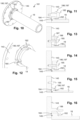
- Figure 10 shows a bushing structure 181 comprising a reference body 143 attached to a bushing 18. They are aligned by the respective second reference surface 145 and alignment surface 184 being pressed against one another, by bushing screws 185.
- Figure 11 shows a detail of a sectional view of Figure 10 , with a bushing screw 185.
- the bushing screw 185 can be arranged in a radial slot in the bushing flange 182, simplifying its manufacturing.
- the bushing screws 185 hold the bushing 18 by a bushing flange 182 against the reference body 143.
- connection ring 187 typically made of a metal material, is pressed by the bushing screws 185 against the bushing flange 182, typically made of a ceramic material, in one piece with the remainder of the bushing 18.
- the connection ring 187 distributes the force of the bushing screws 185 over the potentially brittle surface of the bushing flange 182.
- the connection ring 187 can introduce some resilience in the stack of elements compressed by the bushing screw 185, thereby preventing the bushing screws 185 from loosening.
- the connection ring 187 can be a plate spring or disk spring. In this case, the connection ring 187 shall be called bushing spring 186.
- Figure 12 shows the same basic structure as Figures 10 and 11 , but with the connection ring 187 more clearly shown to be acting as bushing spring 186.
- the connection ring 187 or bushing spring 186 can be shaped to have resilient sections that are compressed and bent by the bushing screws 185 when the bushing screws 185 are tightened.
- Figures 10 and 11 show the bushing spring 186 being entirely compressed an thus in a flat state.
- Figure 13 shows a separate connection ring 187 and bushing spring 186.
- the bushing flange 182 is, in the radial direction, shorter as in the preceding figures, and the bushing screws 185 press the bushing spring 186, near its inner periphery, against the bushing flange 182 and, near its outer periphery, against the connection ring 187.
- the shorter bushing makes it easier to manufacture.
- Figure 14 shows the connection ring 187 again having the function of a bushing spring 186.
- the connection ring 187 can act as a plate spring as it is screwed against the reference body 143.
- Figure 15 shows a structurally similar arrangement as Figure 14 , but with different proportions of the connection ring 187 or bushing spring 186, being in the form of a piece of bent sheet metal.
- Figure 16 shows an attachment element 188 with an axially extending finger that is bent to hold the bushing flange 182 against the reference body 143.
- the attachment element 188 is shaped as part of the reference body 143. Alternatively (not shown) it can be attached to the reference body 143 by other means. Typically, it is in the form of a ring or ring-shaped wall supporting multiple fingers, or the fingers extend separately from the reference body 143, without being connected by a ring.
Landscapes
- Engineering & Computer Science (AREA)
- General Engineering & Computer Science (AREA)
- Mechanical Engineering (AREA)
- Power Engineering (AREA)
- Physics & Mathematics (AREA)
- Fluid Mechanics (AREA)
- Motor Or Generator Frames (AREA)
Priority Applications (5)
| Application Number | Priority Date | Filing Date | Title |
|---|---|---|---|
| EP23169426.6A EP4456385A1 (de) | 2023-04-24 | 2023-04-24 | Elektrische hochgeschwindigkeitsmaschine |
| KR1020257034524A KR20260005883A (ko) | 2023-04-24 | 2024-04-22 | 고속 전기 기계 |
| CN202480027436.1A CN121079878A (zh) | 2023-04-24 | 2024-04-22 | 高速电机 |
| EP24721597.3A EP4702651A1 (de) | 2023-04-24 | 2024-04-22 | Elektrische hochgeschwindigkeitsmaschine |
| PCT/EP2024/060919 WO2024223478A1 (en) | 2023-04-24 | 2024-04-22 | High speed electrical machine |
Applications Claiming Priority (1)
| Application Number | Priority Date | Filing Date | Title |
|---|---|---|---|
| EP23169426.6A EP4456385A1 (de) | 2023-04-24 | 2023-04-24 | Elektrische hochgeschwindigkeitsmaschine |
Publications (1)
| Publication Number | Publication Date |
|---|---|
| EP4456385A1 true EP4456385A1 (de) | 2024-10-30 |
Family
ID=86185001
Family Applications (2)
| Application Number | Title | Priority Date | Filing Date |
|---|---|---|---|
| EP23169426.6A Withdrawn EP4456385A1 (de) | 2023-04-24 | 2023-04-24 | Elektrische hochgeschwindigkeitsmaschine |
| EP24721597.3A Pending EP4702651A1 (de) | 2023-04-24 | 2024-04-22 | Elektrische hochgeschwindigkeitsmaschine |
Family Applications After (1)
| Application Number | Title | Priority Date | Filing Date |
|---|---|---|---|
| EP24721597.3A Pending EP4702651A1 (de) | 2023-04-24 | 2024-04-22 | Elektrische hochgeschwindigkeitsmaschine |
Country Status (4)
| Country | Link |
|---|---|
| EP (2) | EP4456385A1 (de) |
| KR (1) | KR20260005883A (de) |
| CN (1) | CN121079878A (de) |
| WO (1) | WO2024223478A1 (de) |
Citations (9)
| Publication number | Priority date | Publication date | Assignee | Title |
|---|---|---|---|---|
| US3302048A (en) * | 1965-09-23 | 1967-01-31 | Barden Corp | Self-aligning gas bearing |
| JPH066739U (ja) | 1992-06-30 | 1994-01-28 | エヌティエヌ株式会社 | 静圧気体軸受スピンドル装置 |
| CN102223007A (zh) * | 2011-06-24 | 2011-10-19 | 罗立峰 | 高速永磁电动机/发电机 |
| CN105889096A (zh) * | 2016-05-06 | 2016-08-24 | 同济大学 | 燃料电池发动机的两级串联增压直驱离心式空压机 |
| WO2017202941A1 (en) | 2016-05-25 | 2017-11-30 | Celeroton Ag | Electrical machine and rotor for an electrical machine |
| WO2020002509A1 (en) | 2018-06-29 | 2020-01-02 | Celeroton Ag | Electrical machine |
| CN110821951A (zh) * | 2018-08-09 | 2020-02-21 | 博格华纳公司 | 支承系统 |
| KR20200071343A (ko) * | 2018-12-11 | 2020-06-19 | 김병국 | 초고속 전동기 |
| US20200400148A1 (en) * | 2019-06-21 | 2020-12-24 | Lg Electronics Inc. | Motor assembly and method for manufacturing the same |
-
2023
- 2023-04-24 EP EP23169426.6A patent/EP4456385A1/de not_active Withdrawn
-
2024
- 2024-04-22 KR KR1020257034524A patent/KR20260005883A/ko active Pending
- 2024-04-22 CN CN202480027436.1A patent/CN121079878A/zh active Pending
- 2024-04-22 WO PCT/EP2024/060919 patent/WO2024223478A1/en not_active Ceased
- 2024-04-22 EP EP24721597.3A patent/EP4702651A1/de active Pending
Patent Citations (10)
| Publication number | Priority date | Publication date | Assignee | Title |
|---|---|---|---|---|
| US3302048A (en) * | 1965-09-23 | 1967-01-31 | Barden Corp | Self-aligning gas bearing |
| JPH066739U (ja) | 1992-06-30 | 1994-01-28 | エヌティエヌ株式会社 | 静圧気体軸受スピンドル装置 |
| CN102223007A (zh) * | 2011-06-24 | 2011-10-19 | 罗立峰 | 高速永磁电动机/发电机 |
| CN105889096A (zh) * | 2016-05-06 | 2016-08-24 | 同济大学 | 燃料电池发动机的两级串联增压直驱离心式空压机 |
| WO2017202941A1 (en) | 2016-05-25 | 2017-11-30 | Celeroton Ag | Electrical machine and rotor for an electrical machine |
| WO2020002509A1 (en) | 2018-06-29 | 2020-01-02 | Celeroton Ag | Electrical machine |
| US20210242747A1 (en) * | 2018-06-29 | 2021-08-05 | Celeroton Ag | Electrical machine |
| CN110821951A (zh) * | 2018-08-09 | 2020-02-21 | 博格华纳公司 | 支承系统 |
| KR20200071343A (ko) * | 2018-12-11 | 2020-06-19 | 김병국 | 초고속 전동기 |
| US20200400148A1 (en) * | 2019-06-21 | 2020-12-24 | Lg Electronics Inc. | Motor assembly and method for manufacturing the same |
Also Published As
| Publication number | Publication date |
|---|---|
| WO2024223478A1 (en) | 2024-10-31 |
| CN121079878A (zh) | 2025-12-05 |
| KR20260005883A (ko) | 2026-01-12 |
| EP4702651A1 (de) | 2026-03-04 |
Similar Documents
| Publication | Publication Date | Title |
|---|---|---|
| US11750058B2 (en) | Electrical machine and rotor for an electrical machine | |
| US11817760B2 (en) | Electrical machine | |
| US20180013325A1 (en) | Electrical machine | |
| CN109309413B (zh) | 转子、旋转电机以及转子的制造方法 | |
| EP4456385A1 (de) | Elektrische hochgeschwindigkeitsmaschine | |
| JP4723595B2 (ja) | ガスタービン用永久磁石発電機ロータ、その製造方法及びガスタービン | |
| JP2008515365A (ja) | クランプ装置を備えた回転子 | |
| US11811280B2 (en) | Squirrel-cage rotor and associated asynchronous electrical machine | |
| EP2167807B1 (de) | Spaltbiegefederungssystem und verfahren für einen kryokühler | |
| CN111365293B (zh) | 压缩机转子、压缩机及空调设备 | |
| JP3302705B2 (ja) | 超電導回転電機の回転子 | |
| CN104675700B (zh) | 螺杆压缩机 | |
| KR20260007570A (ko) | 고속 전기 기계 | |
| CN121066847A (zh) | 一种紧凑型大风量抗冲振轴流风机 |
Legal Events
| Date | Code | Title | Description |
|---|---|---|---|
| PUAI | Public reference made under article 153(3) epc to a published international application that has entered the european phase |
Free format text: ORIGINAL CODE: 0009012 |
|
| STAA | Information on the status of an ep patent application or granted ep patent |
Free format text: STATUS: THE APPLICATION HAS BEEN PUBLISHED |
|
| AK | Designated contracting states |
Kind code of ref document: A1 Designated state(s): AL AT BE BG CH CY CZ DE DK EE ES FI FR GB GR HR HU IE IS IT LI LT LU LV MC ME MK MT NL NO PL PT RO RS SE SI SK SM TR |
|
| STAA | Information on the status of an ep patent application or granted ep patent |
Free format text: STATUS: THE APPLICATION IS DEEMED TO BE WITHDRAWN |
|
| 18D | Application deemed to be withdrawn |
Effective date: 20250501 |